1stGen AHSS, AHSS, Steel Grades
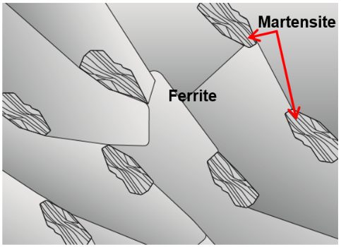
Dual Phase (DP) steels have a microstructure consisting of a ferritic matrix with martensitic islands as a hard second phase, shown schematically in Figure 1. The soft ferrite phase is generally continuous, giving these steels excellent ductility. When these steels deform, strain is concentrated in the lower-strength ferrite phase surrounding the islands of martensite, creating the unique high initial work-hardening rate (n-value) exhibited by these steels. Figure 2 is a micrograph showing the ferrite and martensite constituents.
Figure 1: Schematic of a Dual Phase steel microstructure showing islands of martensite in a matrix of ferrite.
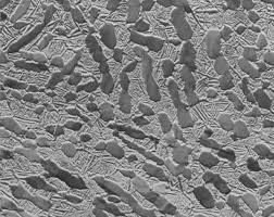
Figure 2: Micrograph of Dual Phase Steel
Hot rolled DP steels do not have the benefit of an annealing cycle, so the dual phase microstructure must be achieved by controlled cooling from the austenite phase after exiting the hot strip mill finishing stands and before coiling. This typically requires a more highly alloyed chemistry than cold rolled DP steels require. Higher alloying is generally associated with a change in welding practices.
In one possible approach, after exiting the last finishing stand of the hot rolling mill, controlled cooling facilitates the nucleation of ferrite. Then a more rapid cooling fast enough to avoid bainite formation is needed to reach the Ms (martensite start) temperature and begin nucleating martensite from the austenite that had not transformed to ferrite.
Continuously annealed cold-rolled and hot-dip coated Dual Phase steels are produced by controlled cooling from the two-phase ferrite plus austenite (α + γ) region to transform some austenite to ferrite before a rapid cooling transforms the remaining austenite to martensite. Due to the production process, small amounts of other phases (bainite and retained austenite) may be present.
Higher strength dual phase steels are typically achieved by increasing the martensite volume fraction. Depending on the composition and process route, steels requiring enhanced capability to resist cracking on a stretched edge (as typically measured by hole expansion capacity) can have a microstructure containing significant quantities of bainite.
The work hardening rate plus excellent elongation creates DP steels with much higher ultimate tensile strengths than conventional steels of similar yield strength. Figure 3 compares the engineering stress-strain curve for HSLA steel to a DP steel curve of similar yield strength. The DP steel exhibits higher initial work hardening rate, higher ultimate tensile strength, and lower YS/TS ratio than the HSLA with comparable yield strength. Additional engineering and true stress-strain curves for DP steel grades are presented in Figures 4 and 5.
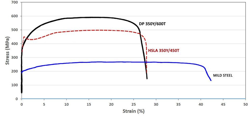
Figure 3: A comparison of stress strain curves for mild steel, HSLA 350/450, and DP 350/600K-1

Figure 4: Engineering stress-strain curves for a series of DP steel grades.S-5, V-1 Sheet thicknesses: DP 250/450 and DP 500/800 = 1.0mm. All other steels were 1.8-2.0mm.

Figure 5: True stress-strain curves for a series of DP steel grades.S-5, V-1 Sheet thicknesses: DP 250/450 and DP 500/800 = 1.0mm. All other steels were 1.8-2.0mm.
The volume fraction, morphology, and distribution of the martensite in the ferrite matrix is responsible for the mechanical properties of dual phase (DP) steels. The intercritical annealing temperature, cooling rate, and alloy content affect the martensite volume fraction in the finished product.
Martensite can have different appearances (morphologies) in the microstructure including needle-like, granular, and equiaxed, and these impact the strength and ductility of DP steels. The most favorable balance of strength and ductility usually is associated with a uniform distribution of equiaxed martensite islands.
These properties influence the hole expansion ratio, which measures the expandability of a sheared edge. The amount of carbon in martensite controls martensite hardness relative to the ferrite, and a greater hardness difference between martensite and ferrite is associated with decreased HER values.
The number of martensite colonies per unit area has a positive correlation with sheared edge stretchability, indicating that there is a greater dispersion of these islands of this high-hardness phase. A more homogeneous microstructure is known to have better HER and sheared-edge formability properties.T-57.
Although dual phase steels are more formable than HSLA steels at the same tensile strength, there is a greater risk of cut edge fractures forming and propagating during stretch flanging. This is due to the hardness difference between the ferrite and martensite phases.
In these steels, micro-voids form at the interface between the soft phase and hard phase at the sheared edge (Figure 6), and can fracture during flanging under tension. Reducing the hardness difference of the microstructural components is one approach to improve edge fracture resistance, which is one of the merits of using complex phase steels.

Figure 6: Microstructure at the punched edge of a DP steel.M-75
DP and other AHSS also have a bake hardening effect that is an important benefit compared to conventional higher strength steels. The extent of the bake hardening effect in AHSS depends on an adequate amount of forming strain for the specific chemistry and thermal history of the steel.
In DP steels, carbon enables the formation of martensite at practical cooling rates by increasing the hardenability of the steel. Manganese, chromium, molybdenum, vanadium, and nickel, added individually or in combination, also help increase hardenability. Carbon also strengthens the martensite as a ferrite solute strengthener, as do silicon and phosphorus. These additions are carefully balanced, not only to produce unique mechanical properties, but also to maintain the generally good resistance spot welding capability. However, when welding the higher strength grades (DP 700/1000 and above) to themselves, the spot weldability may require adjustments to the welding practice.
Dual Phase Steel for Exposed Panels
In recent decades, bake hardenable steels have been a common choice for outer surface panels. Many of these applications center around grades with yield strength of approximately 200 MPa and tensile strength below approximately 400 MPa. Work hardening (strengthening occurring from forming) combined with bake hardening (strengthening from the paint curing cycle during automotive production) usually adds around 70 to 100 MPa to the yield strength, enhancing the dent resistance of these panels.
To further support the lightweighting efforts of the automobile industry, steelmakers have developed dual phase steels with appropriate surface characteristics for exposed panel applications. The benefits of deploying dual phase steels in these applications include a higher yield strength from the steel mill (300 MPa minimum yield strength) and a greater strengthening increase from bake hardening (typically more than 100 MPa) in addition to the work hardening from forming. The strengthening increase allows the automaker to downgauge the sheet thickness to as low as 0.55 mm and maintain adequate dent resistance. More information on the bake hardenability of exposed quality dual phase steels can be found here.
The primary grade in this category can be described as HC300/500DPD+Z, where HC indicates that it is high strength cold rolled steel, 300/500 represents the minimum yield and tensile strength in MPa, DPD is “dual phase deep drawing,” and Z indicates that it is galvanized.
The stress-strain curves of HC300/500DPD+Z are compared with those of common traditional bake hardening grades used for automotive outer skin panels in Figures 7 and 8. The comparison of engineering stress-strain curves are shown in Figure 7, with Figure 8 comparing the true stress-strain curves.
The dual phase steel exhibits a higher tensile strength and greater work hardening (n-value) – especially in the 4% to 6% range that coincides with the strain range associated with stamping automotive outer panels.
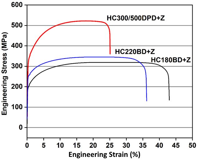
Figure 7: Engineering stress-strain curves for 0.6 mm HC300Y/500T-DPD+Z (galvanized 500 DP in red), 0.75 mm HC220BD+Z (galvanized 220 BH in blue), and 0.65 mm HC180BD+Z (galvanized 180 BH in black).
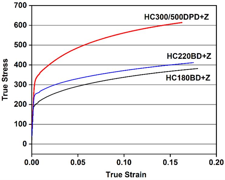
Figure 8: True stress-strain curves for 0.6 mm HC300Y/500T-DPD+Z (galvanized 500 DP in red), 0.75 mm HC220BD+Z (galvanized 220 BH in blue), and 0.65 mm HC180BD+Z (galvanized 180 BH in black).
Figure 9 compares the forming limit curve for HC300/500DPD+Z steel to those of the typical bake hardenable grades. The dual phase grade has comparable to slightly less necking resistance than HC220BD+Z, a bake hardenable steel with 220 MPa minimum tensile strength. The necking resistance of HC180BD+Z is greater than both other grades.
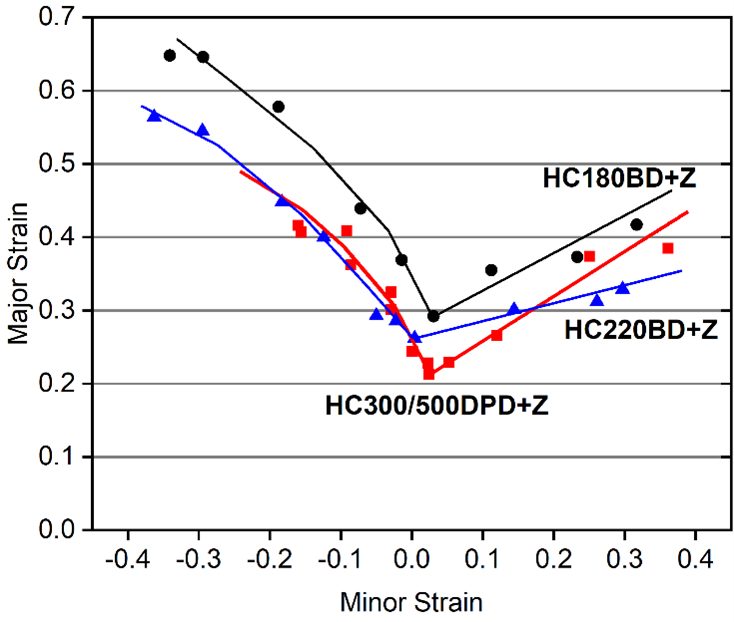
Figure 9: Forming limit curves for 0.6 mm HC300Y/500T-DPD+Z (galvanized 500 DP in red), 0.75 mm HC220BD+Z (galvanized 220 BH in blue), and 0.65 mm HC180BD+Z (galvanized 180 BH in black).
While the thickness reduction offered by HC300/500DPD+Z benefits lightweighting, there is also an associated loss of stiffness. This reduced stiffness typically limits how thin automakers will specify for surface panels, rather than steel mill capabilities.
However, the lower stiffness, higher yield strength, and lower formability negatively influence dimensional accuracy and may contribute to welding challenges. Many of these challenges can be addressed virtually using metal forming simulation.
Examples of current production grades of DP steels and typical automotive applications include:
| DP 300/500 |
Roof outer, door outer, body side outer, package tray, floor panel |
| DP 350/600 |
Floor panel, hood outer, body side outer, cowl, fender, floor reinforcements |
| DP 500/800 |
Body side inner, quarter panel inner, rear rails, rear shock reinforcements |
| DP 600/980 |
Safety cage components (B-pillar, floor panel tunnel, engine cradle, front sub-frame package tray, shotgun, seat) |
| DP 700/1000 |
Roof rails |
| DP 800/1180 |
B-Pillar upper |
Some of the specifications describing uncoated cold rolled 1st Generation dual phase (DP) steel are included below, with the grades typically listed in order of increasing minimum tensile strength and ductility. Different specifications may exist which describe hot or cold rolled, uncoated or coated, or steels of different strengths. Many automakers have proprietary specifications which encompass their requirements.
- ASTM A1088, with the terms Dual phase (DP) steel Grades 440T/250Y, 490T/290Y, 590T/340Y, 780T/420Y, and 980T/550YA-22
- EN 10338, with the terms HCT450X, HCT490X, HCT590X, HCT780X, HCT980X, HCT980XG, and HCT1180XD-6
- JIS G3135, with the terms SPFC490Y, SPFC540Y, SPFC590Y, SPFC780Y and SPFC980YJ-3
- JFS A2001, with the terms JSC590Y, JSC780Y, JSC980Y, JSC980YL, JSC980YH, JSC1180Y, JSC1180YL, and JSC1180YHJ-23
- VDA 239-100, with the terms CR290Y490T-DP, CR330Y590T-DP, CR440Y780T-DP, CR590Y980T-DP, and CR700Y980T-DPV-3
- SAE J2745, with terms Dual Phase (DP) 440T/250Y, 490T/290Y, 590T/340Y, 6907/550Y, 780T/420Y, and 980T/550YS-18
Resistance Spot Welding
Parameter Guidelines
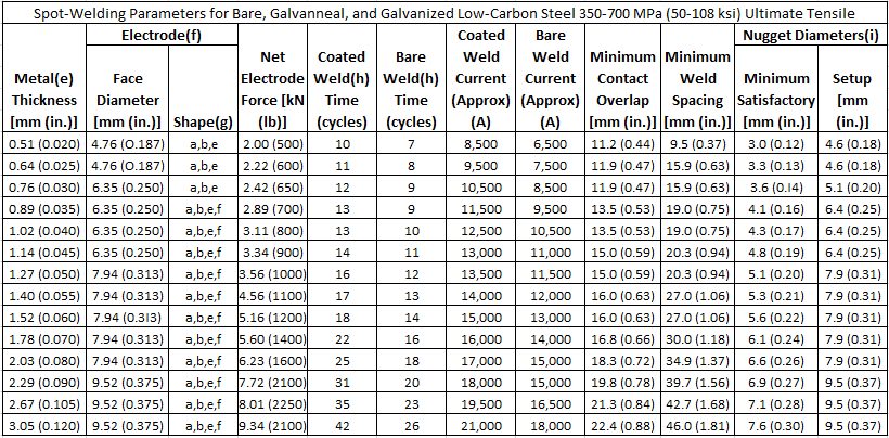
In summary, Tables 1 and 2 provide the AWS C1.1 Spot Welding Parameter Guidelines link to Recommended Practices for Resistance Welding. These general guidelines can be used to approximate which parameters can be used to begin the Resistance Spot Welding (RSW) process of a specific part thickness. From the recommended parameters, changes can be made on a specific stack-up to ensure an acceptable strength and nugget size for a particular application. Additionally, more complicated RSW parameter guidelines using a pulsation welding schedule with AC 60 Hz for welding AHSS is included in Table 3.
Table 1: Spot welding parameters for low-carbon steel 350-700 MPa (AHSS).A-14
- Use of coated parameters recommended with the presence of a coating at any faying surface.
- These recommendations are based on available weld schedules representing recommendations from resistance welding equipment suppliers and users.
- For intermediate thicknesses parameters may be interpolated.
- Minimum weld button shear strength determined as follows:
- ST = ((-8.83×10⁻⁷ × S2 + 1.34×10⁻³ × S + 1.514) × S × 4t1.5)/1000
- ST = Shear Tension Strength (kN)
- S = Base Metal Tensile Strength (MPa)
- t = Material Thickness (mm)
- Metal thicknesses represent the actual thickness of the sheets being welded. In the case of welding two sheets of different thicknesses, use the welding parameters for the thinner sheet.
- Welding parameters are applicable when using electrode materials included in RWMA Classes 1 , 2, and 20.
- Electrode shapes listed include: A-pointed, B-domed, E-truncated, F-radiused. Figure 2 shows these shapes.
- The use of Type-B geometry may require a reduction in current and may result in excessive indentation unless face is dressed to specified diameter.
- The use of Type F geometry may require an increase in current.
- Welding parameters are based on single-phase AC 60 Hz equipment.
- Nugget diameters are listed as:
- Minimum diameter that is recommended to be considered a satisfactory weld.
- Initial aim setup nugget diameter that is recommended in setting up a weld station to produce nuggets that consistently surpass the satisfactory weld nugget diameter for a given number of production welds.
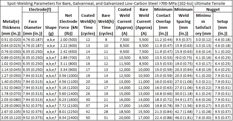
Table 2: Spot welding parameters for low-carbon steel >700 MPa (AHSS). A-14
- Use of coated parameters recommended with the presence of a coating at any faying surface.
- These recommendations are based on available weld schedules representing recommendations from resistance welding equipment suppliers and users.
- For intermediate thicknesses parameters may be interpolated.
- Minimum weld button shear strength determined as follows:
- ST = ((-8.83×10⁻⁷ × S2 + 1.34×10⁻³ × S + 1.514) × S × 4t1.5)/1000
- ST = Shear Tension Strength (kN)
- S = Base Metal Tensile Strength (MPa)
- t = Material Thickness (mm)
- Metal thicknesses represent the actual thickness of the sheets being welded. In the case of welding two sheets of different thicknesses, use the welding parameters for the thinner sheet.
- Welding parameters are applicable when using electrode materials included in RWMA Classes 1, 2, and 20.
- Electrode shapes listed include: A-pointed, B-domed, E-truncated, F-radiused. Figure 2 shows these shapes.
- The use of Type-B geometry may require a reduction in current and may result in excessive indentation unless face is dressed to specified diameter.
- The use of Type F geometry may require an increase in current.
- Welding parameters are based on single-phase AC 60 Hz equipment.
- Nugget diameters are listed as:
- Minimum diameter that is recommended to be considered a satisfactory weld.
- Initial aim setup nugget diameter that is recommended in setting up a weld station to produce nuggets that consistently surpass the satisfactory weld nugget diameter for a given number of production welds.
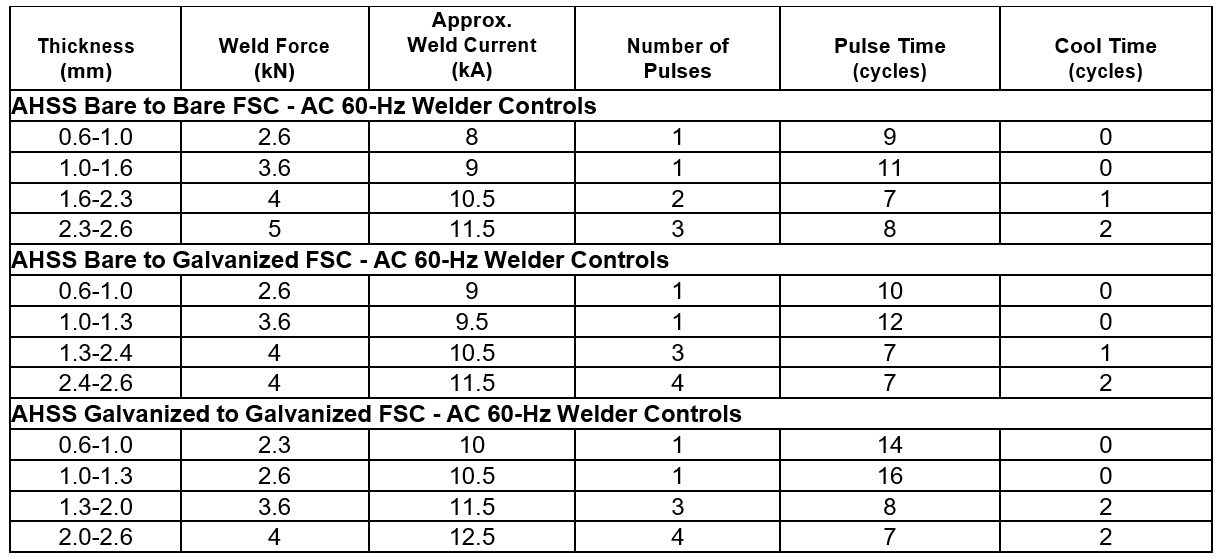
Table 3: AHSS bare-to-bare, bare-to-galvanized, Galvanized-to-galvanized RSW parameters for pulsating AC 60 Hz.A-14
Heat, Material and Thickness Balances
The heat input in Resistance Spot Welding (RSW) is defined as:
Heat Input = I2Rt
where: I is welding current
R is total resistance, and
t is weld time
The heat input must be changed depending on the gauge and grade of the steel. Compared to low strength steel at a particular gauge, the AHSS at the same gauge will need less current. Similarly, the thin gauge material needs less current than thick gauge. Controlling the heat input according to the gauge and grade is called heat balance in RSW.
For constant thickness, Table 1 shows steel classification based on strength level. With increasing group numbers, higher electrode force, longer weld time, and lower current are required for satisfactory RSW. Material combinations with one group difference can be welded with little or no changes in weld parameters. Difference of two or three groups may require special considerations in terms of electrode cap size, force, or type of power source.
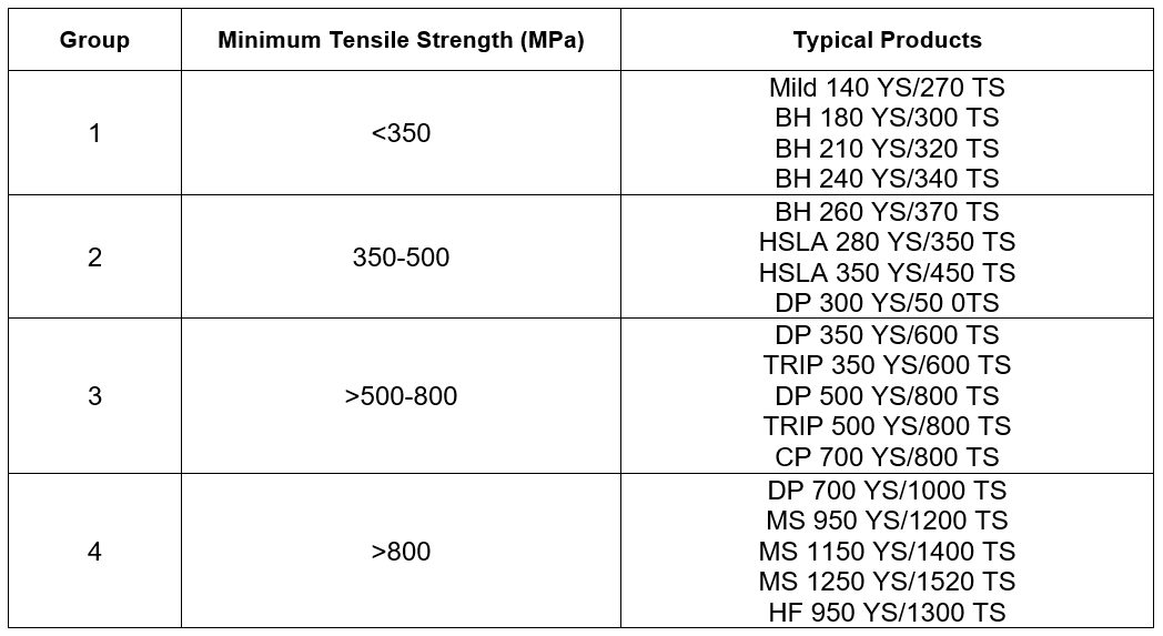
Table 1: Steel classification for RSW purposes.A-11
For a particular steel grade, changes in thickness may require adoption of special schedules to control heat balance. When material type and gauge are varied together, specific weld schedules may need to be developed. Due to the higher resistivity of AHSS, the nugget growth occurs preferentially in AHSS. Electrode life on the AHSS-side may be reduced due to higher temperature on this side. In general, electrode life when welding AHSS may be similar to mild steel because of lower operating current requirement due to higher bulk resistivity in AHSS. This increase in electrode life may be offset in production due to poor part fit up created by higher AHSS springback. Frequent tip dressing will maintain the electrode tip shape and help achieve consistently acceptable quality welds.
Welding Current Mode
AHSS can be welded with power sources operated with either AC or DC types (Figure 1). Middle-Frequency Direct-Current (MFDC) has an advantage over conventional AC due to both unidirectional and continuous current. These characteristics assist in controlling and directing the heat generation at the interface. Current mode has no significant difference in weld quality. It should be noted that both AC and DC can easily produce acceptable welds where thickness ratios are less than 2:1. However, some advantage may be gained using DC where thickness ratios are over 2:1, but welding practices must be developed to optimize the advantages. It also has been observed that nugget sizes are statistically somewhat larger when using DC welding with the same secondary weld parameters than with AC. Some studies have shown that welding with MFDC provides improvements in heat balance and weld process robustness when there is a thickness differential in AHSS (as shown in Figure 2). DC power sources have been reported to provide better power factors and lower power consumption than AC power sources. Specifically, it has been reported that AC requires about 10% higher energy than DC to make the same size weld.L-7
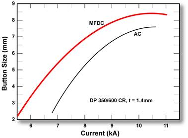
Figure 1: Range for 1.4-mm DP 350/600 CR steel at different current modes with a single pulse.L-2
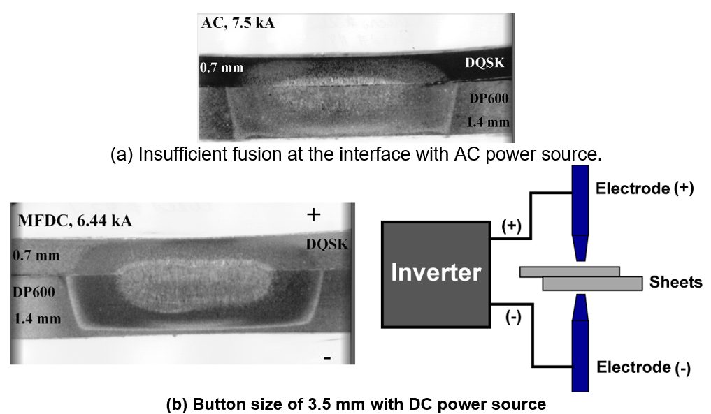
Figure 2: Effect of current mode on dissimilar-thickness stack-up.L-2
Consult safety requirements for your area when considering MFDC welding for manual weld gun applications. The primary feed to the transformers contains frequencies and voltages higher than for AC welding.
Back To Top
Resistance Spot Welding
In general, if any type of AHSS [Dual-Phase (DP), Transformation-Induced Plasticity (TRIP), Complex Phase (CP), Ferrite Bainite (FB), or Martensitic (MS)] is used for the first time, the user should take the welding schedules applied to mild steel and then:
- Increase the electrode force by 20% or more depending on Yield Strength.
- Increase weld time as appropriate.
If these changes are insufficient, try these additional changes:
- A multi-pulse welding schedule (several pulses or post heating).
- Larger tip diameter and/or change the type of electrode.
- Increase the minimum weld size.
When resistance welded, AHSS require less current than conventional mild steel or HSLA because AHSS have higher electrical resistivity. Therefore, current levels for AHSS are not increased and may even need to be reduced depending on material chemical composition. However, most AHSS grades may require higher electrode forces for equivalent thickness of mild steels because electrode force depends on material strength. If thick mild steel or HSLA steel (of the same thickness) is replaced by an equivalent thickness of AHSS, the same forces may be required during assembly welding.
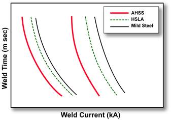
AHSS often have tighter weld windows (welding parameters that give acceptable welds) when compared to mild steels, as shown in the Figure 1.
Figure 1: Schematic weld lobes for AHSS, HSLA, and mild steel with a shift to lower currents with increased strength.
The current range (kA) for AHSS of 600-1400MPa during RSW is shown in Figures 2 and 3. The process window for Resistance Spot Welding of AHSS is influenced by the electrode force and welding time used in a major way. The current range increases by an average of 500 A for every additional 500 N of electrode force (Figure 2). The current range also increases by an average of 250 A for each additional 40 ms of welding time (Figure 3). Extra amounts of electrode force and welding time lead to increased current range, allowing for a wider process window.
Figure 2: RSW with AHSS, current range for varying electrode force (Cap Type B 16/6, 6-mm tip diameter, single pulse, 340-ms weld time, 250-ms hold time, plug failures.).I-6
Figure 3: RSW with AHSS, current range for varying weld time (Cap Type B 16/6, 6-mm tip diameter, single pulse, 3.5-kN electrode force, 250-ms hold time, plug failures.).O-1
A more extensive weld studyT-5 of three DP HDGA (45/45 g/m2) coated steels showed similar welding behavior for all three steels. The 1.6-mm-thick steels were DP 340/590, DP 420/780, and DP 550/980. To characterize the welding behavior of the steels, useful current ranges and static weld tensile tests were performed. The useful current range is the difference between the welding current required to produce a minimum button size (Imin) and the current that causes expulsion of weld metal (Imax). In this study, the 4√t as the minimum button diameter was used, where “t” is the nominal sheet thickness. This is generally used in the automotive and steel industries. The weld current range was 2.2 kA for the DP 340/590 and DP 420/780 and 2.5 kA for the DP 550/980 steel (Figure 4). These current ranges are sufficiently wide to weld successfully the DP steels. The study also found no weld imperfections, which means these three DP steels are weldable with simple, easy to use welding parameters.
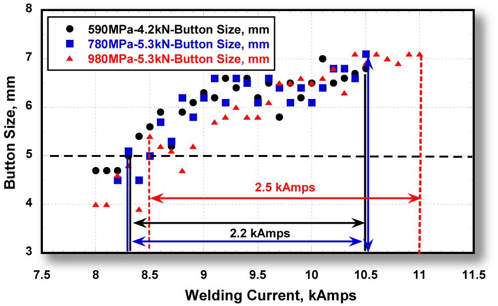
Figure 4: Welding current ranges for 1.6-mm DP HDGA steels with minimum tensile strengths of 590, 780, and 980 MPa.T-5
Average reported weld hardness was 380 HV (Vickers Hardness) for the DP 340/590 and 415 HV for the other two. Again, all three DP steels had similar weld hardness distributions. The study also concluded that weld fracture mode alone is not a good indicator of weld integrity and performance. The load to fracture should be considered more important in judging weld integrity.
A second studyT-6 compared two 1.6-mm-thick HDGA (45/45 g/m2) steels: DP 420/700 and TRIP 420/700. The weld current range for 18 cycles weld time was similar: 1.4 kA for the DP 420/700 and 1.5 kA for the TRIP 420/700. The average weld hardness was 400 HV for both steels. The study concluded that acceptable welds with no imperfections can be produced in both steel grades. Both steel grades are readily weldable with easily adoptable welding parameters. Weld tensile strength differences between the two steels were small and not considered statistically significant.
Weld schedules (Figure 5) with pulsed current profiles for AHSS can have weld-current ranges similar to mild steel. Even though there is no increased tendency for weld expulsion with AHSS avoiding weld expulsion is highly desirable with AHSS. Loss of nugget material can affect weld-nugget size and strength.
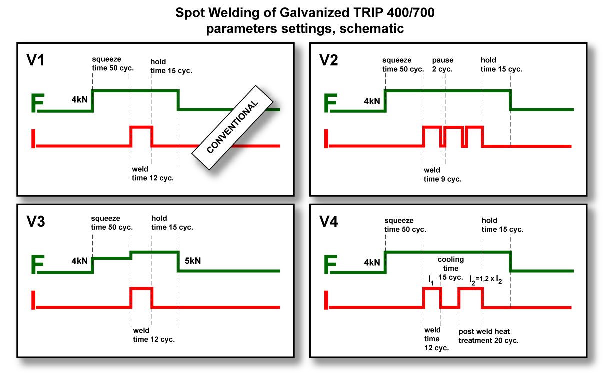
Figure 5: Schematics of optimized weld schedules for AHSS.B-1
Post annealing (tempering pulse weld schedule) of TRIP steel may alter weld fracture mode and weld current range (Figure 6). However, since studies have shown that the occurrence of partial or IF fractures does not necessarily indicate poor weld quality, the use of pulsed current is not required to improve weld quality. Further, the effect of current pulsing on tensile and fatigue properties, as well as the electrode tip life, is not known. Therefore, users should perform their own evaluations regarding the suitability of such modified parameters.
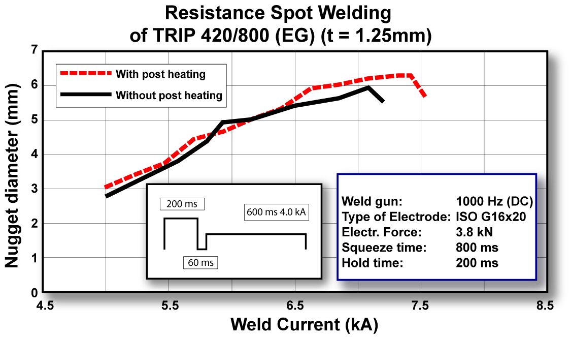
Figure 6: Post annealing may enlarge weld current range.B-1
Additional work using Quench and Partition (Q&P) 980 showed less current required than conventional steels because it has higher electrical resistivity. Due to ultra-high base metal (BM) strength, it needs higher electrode force than conventional steels which have equivalent thickness. The weld lobe of 1.6-mm Q&P 980 is shown in Figure 7 with the pulsed weld time and force of 5.8 kN. The yellow zone of this figure shows the fracture mode of full button (FBF) when peel tested. Some pictures of these weld spots’ fracture mode are captured in Figure 8, for diameters of 6.0 to 7.7 mm.
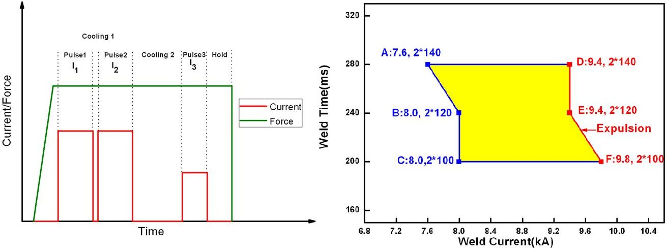
Figure 7: Pulsed current profile and weld lobe of 1_6-mm Q&P 980.B-4
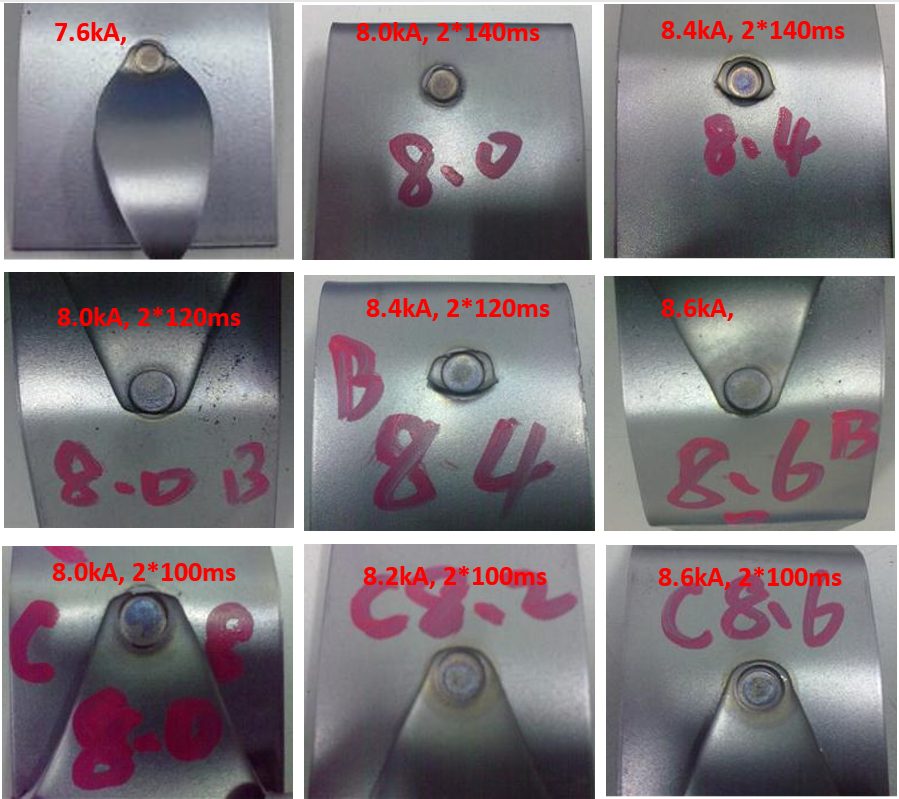
Figure 8: Fracture mode of weld spots in yellow zone.B-4
Hardness measurements and cross sections through the spot weld different zones can be identified as depicted in Figure 9. In a first step, the spot-welded joint can be subdivided into three zones: weld, Heat Affected Zone (HAZ), and BM. The weld is covered by the HAZ, where the melting temperature is not reached but high enough to change the microstructure. This region is dominated by inhomogeneous properties due to the different temperature and cooling gradients. Considering the hardness measurements of AHSS 3 sample, even a softening in the HAZ compared to the BM can be observed. Finally, the HAZ is surrounded by the BM, which does not show any local changes within the structure. These modifications of microstructure in the HAZ and weld are essential for the load-bearing capacity because the strength and ductility are drastically changed in comparison to the BM. Normally a high hardness is related to high strength and less ductility.
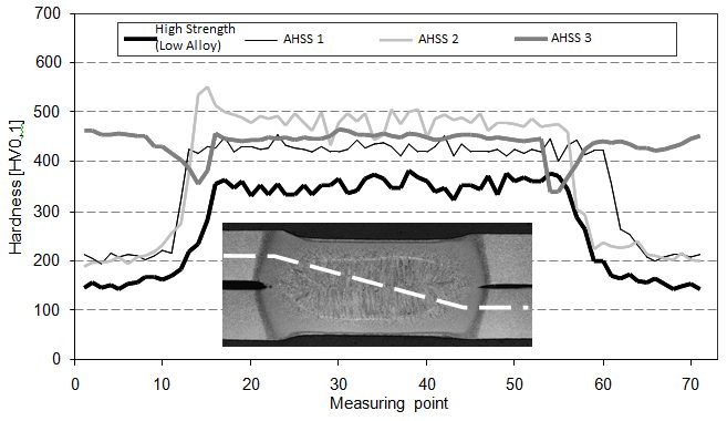
Figure 9: Hardness distribution through spot welds of various strength steels.P-7
Weld spot micrograph and microhardness of 1.6-mm Q&P 980 is shown in Figure 10, in which no weld defects, such as cracks, shrinkage void, pore, no fusion, deep indentation, etc. were found. Hardness testing is typically performed as shown in Figure 11 (diagonal traverse across the weld from BM of top coupon to BM of bottom coupon) using a suitable instrument for micro-indentation hardness testing (Vickers or Knoop).
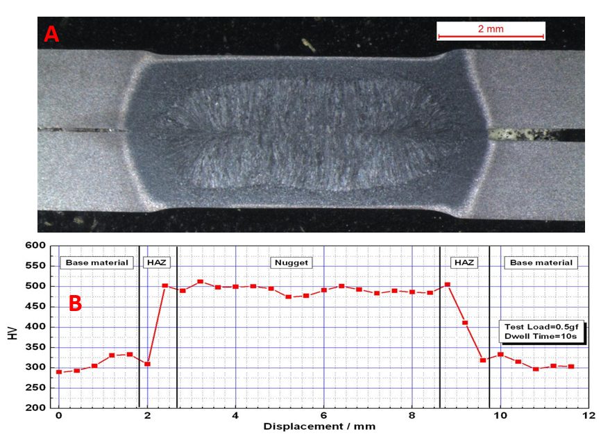
Figure 10: Weld spot micrograph and microhardness of 1.6-mm DP 980.B-4
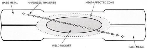
Figure 11: Typical cross-sectioned weld and hardness traverse.A-13
The different hardness values seen in a typical cross-sectioned weld depict different microstructural regions.P-8 Figure 12 shows the temperature distribution of a typical 2T weldment of hot stamped boron steel. At the solidified weld nugget, we see the highest temperatures and steadily decrease toward the unaffected base metal. The weld metal, coarse grain heat affected zone, fine grain heat affected zone, and unaffected base metal are made up of martensitic microstructure. The base metal has this microstructure due to the heat treatment (hot stamping) process. The weld metal, coarse grain heat affected zone, and fine grain heat affected zone are exposed to austenitizing temperature upon welding and are cooled rapidly reforming the martensite microstructure. The subcritical heat affected zone has a unique microstructure of over-tempered martensite. In this region, the peak temperature re below the Ac1, causing the base metal martensitic microstructure to decompose into ferrite and cementite. Micrographs of the different weld regions can be seen in Figure 13.
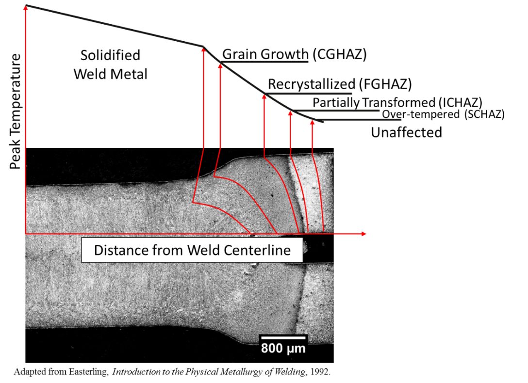
Figure 12: Temperature distribution of a typical 2T RSW of hot stamped boron steel.P-8
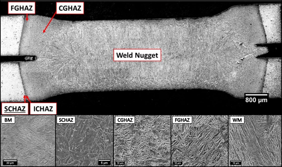
Figure 13: Different microstructures seen throughout the HAZ of a 2T hot stamped boron steel joint.P-8