Examples of mechanical joining in automotive manufacturing are clinching and self-piercing riveting. The process steps and typical equipment for both processes are shown in Figure 1. A simple round punch presses the materials to be joined into the die cavity. As the force continues to increase, the punch side material is forced to spread outward within the die side material.
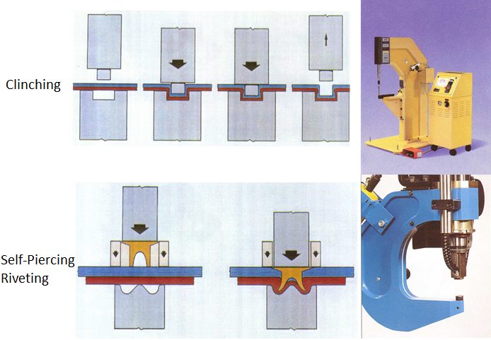
Figure 1: Process steps and equipment for mechanical joining in automotive industries.
This creates an aesthetically round button, which joins cleanly without any burrs or sharp edges that can corrode. Even with galvanized or aluminized sheet metals, the anti-corrosive properties remain intact as the protective layer flows with the material. Table 1 shows characteristics of different mechanical joining methods.
Table 1: Characteristics of mechanical joining systems.T-12
In a recent study conducted to assess the feasibility of clinch joining advanced HSST-8, it was concluded that 780-MPa DP and TRIP [link to steel material grades] steels can be joined to themselves and to low-carbon steel (see Figure 2). However, 980 DP steel showed tears when placed on the die side (Figure 3). These cracks were found at the ferrite- martensite boundaries (Figure 4). However, these tears did not appear to affect the joint strength. More work is needed to improve the local formability of 980 MPa tensile strength DP steel for successful clinch joining.
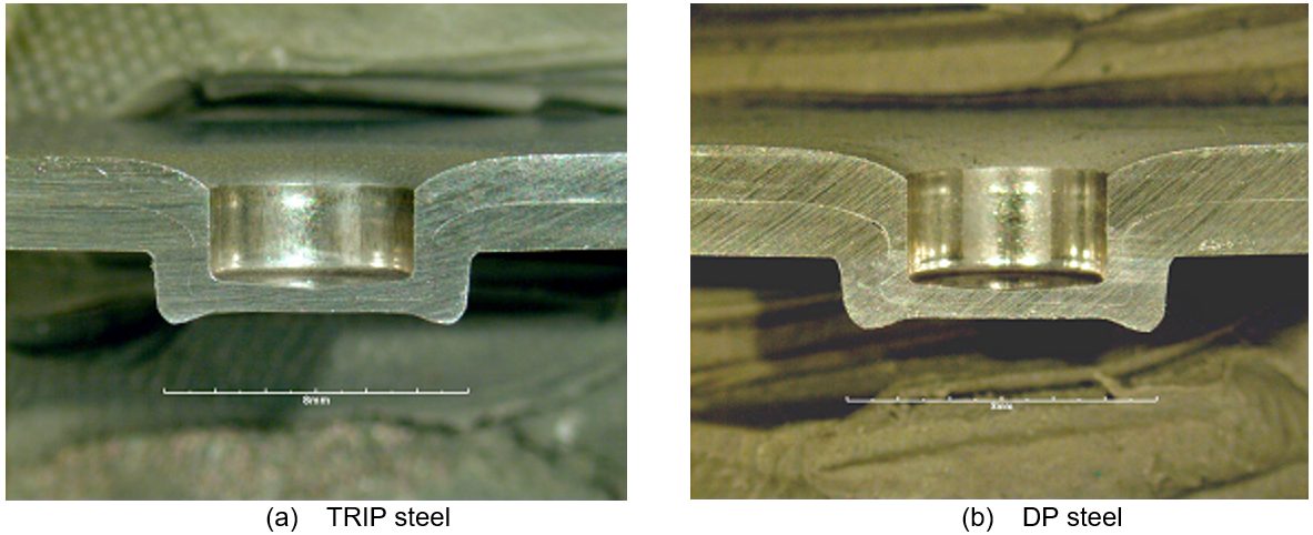
Figure 2: Cross sections of successful clinch joints in 780-MPa tensile.
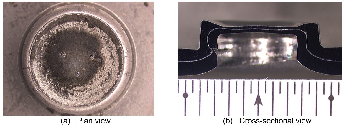
Figure 3: Clinch joint from DP 980-MPa steel showing tears on the die side.
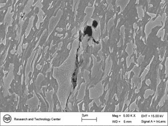
Figure 4: SEM views of tears found in DP 980-MPa steel clinch joints.
Circular clinching without cutting and self-piercing riveting (existing half-hollow-rivets) are not recommended for materials with less than 40% hole expansion ratio (λ) as shown in Figure 5. Clinching with partial cutting may be applied instead.
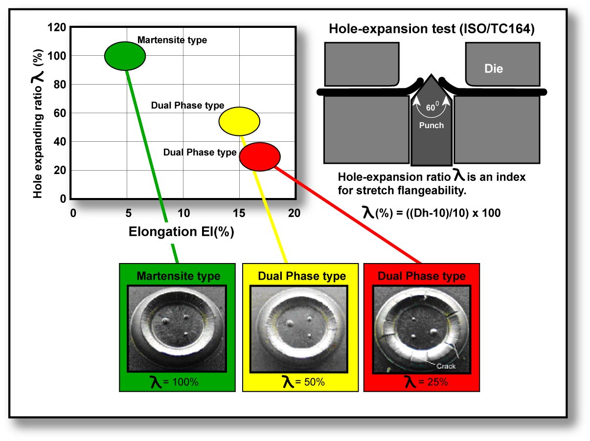
Figure 5: Balance between elongation and stretch flangeability of 980-MPa tensile-strength class AHSS and surface appearance of mechanical joint at the back side.N-1
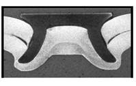
Figure 6: Example of DP 300/500 with a self-piercing rivet.G-2
Warm clinching and riveting are under investigation for material with less than 12T total elongation. As with any steel, equipment size and clinch/pierce force are proportional to the material strength and tool life is inversely proportional to material strength.
The strength of self-piercing riveted AHSS is higher than for mild steels. Figure 4.P-6 shows an example of a self-piercing rivet joining two sheets of 1.5-mm-thick DP 300/500. AHSS with tensile strengths greater than 900 MPa cannot be self-piercing riveted by conventional methods today.
Self-piercing rivet joints are typically similar or slightly weaker in strength when compared to spot welds. It is largely dependent on the punch-die size, design, and rivet size. However, self-piercing rivets usually perform better in fatigue loading compared to spot welds because there is no notch effect such as what exists in spot-welded joints Figure 7 (left)]. Although clinch joining is being used in several automotive applications, their performance is lower as shown in Figure 7 (right). Thus, they are not recommended for critical joints in automotive manufacturing.
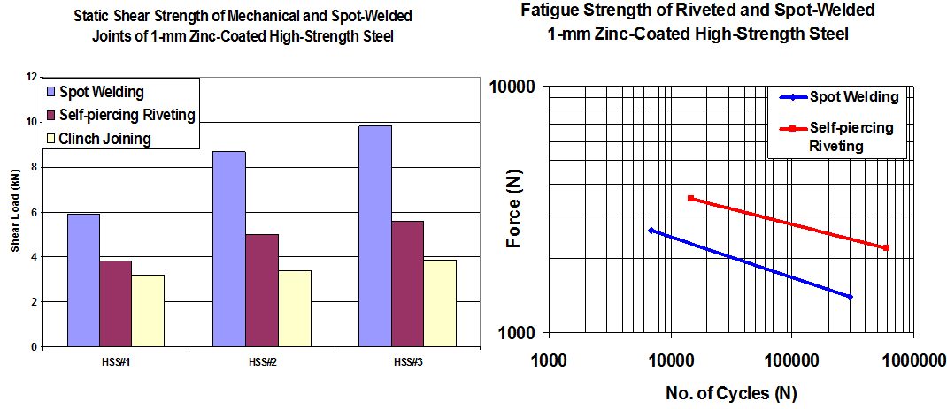
Figure 7: Strength performance for various mechanical joining methods.
Hybrid Riveting Adhesive
Self-piercing rivets can also be combined with adhesives to result in increased initial stiffness, YS, failure loads and fatigue strength when compared to spot welds using adhesives (Figure 8).
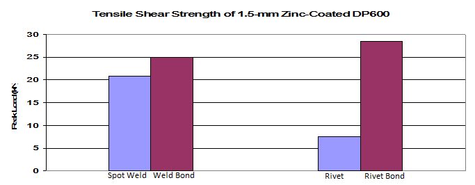
Figure 8: Tensile shear strength of SPR with adhesives and RSW with adhesives.