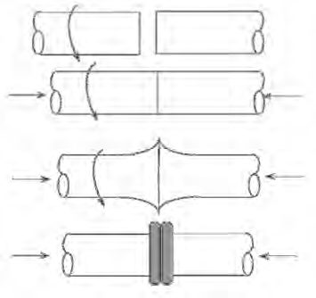
Figure 1: Basic steps of both inertia and CD friction welding.
The Friction Stir Welding family of processes relies on significant plastic deformation or forging action to overcome the barriers to solid-state welding. Frictional heating dominates at the beginning of the process, followed by the heating due to plastic deformation once the forging action begins. The friction welding processes which use rotation of one part against another are inertia and continuous (or direct)-drive friction welding. These are the most common of the friction welding processes and are ideal for round bars or tubes. In both inertia and Continuous-Drive (CD) friction welding, one part is rotated at high speeds relative to the other part (Figure 1). They are then brought together under force creating frictional heating which softens (reduces the YS) the material at and near the joint to facilitate the forging action, which, in turn, produces further heating. Following a sufficient amount of time to properly heat the parts, a high upset force is applied which squeeze the softened hot metal out into the “flash”. Any contaminants are squeezed out as well as the weld is formed. The flash is usually removed immediately after welding while it is still hot.A-11, P-6
Friction Stir Welding
Friction Stir Welding (FSW) is a revolutionary new friction welding process that was developed in the early 1990s by the British Welding Institute (TWI). Whereas processes such as inertia and Continuous-Drive (CD) friction welding are primarily limited to round parts, FSW (Figure 2) produces solid-state friction welds using conventional joint design such as butt joints. FSW relies on the frictional heat created when a special non-consumable pin tool is rotated along the joint against the top of the two pieces being welded. As the process begins, frictional heating softens (or plasticizes) metal at the joint, facilitating a stirring action of plasticized metal. Further heating that is generated by the plastic deformation becomes the main source of heating as the weld progresses. The two videos following provide more insight on the process.
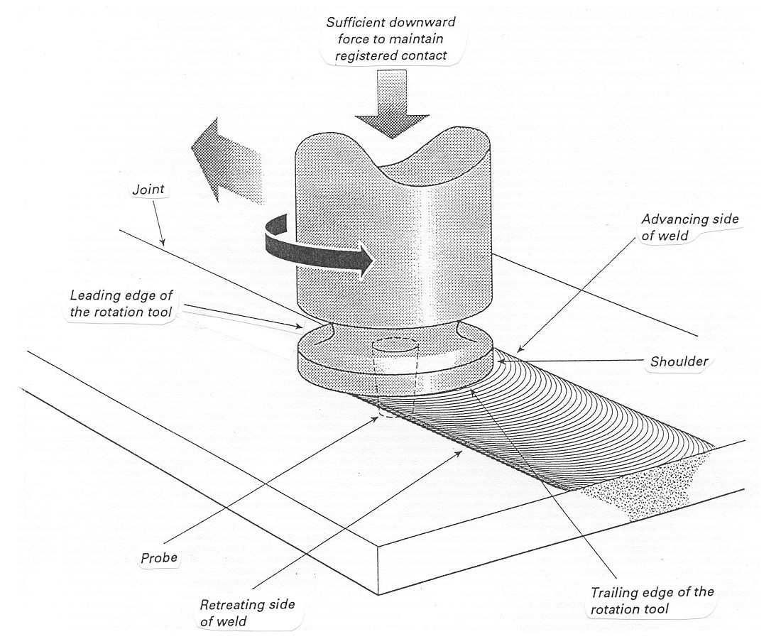
Figure 2: Friction Stir Welding
The pin tool for FSW consists of a shoulder and pin. The shoulder rests on the surface of the plates and provides most of the frictional heating. The pin partially penetrates the joint of the plates being welded. Within the stir zone itself, the plasticized hot metal flows around the pin and coalesces to form a weld. The primary purpose of the pin is to control the stirring action. A wide variety of pin tool designs and materials have been studied, including the use of Tungsten (W)-based materials, threaded pins, and cupped shoulders. As indicated on Figure 3, a slight push angle (<5 degrees) relative to the travel direction is typically used. Weld travel speeds are much slower than typical arc welding speeds. The process has limited industrial applications since it is still under development, especially in tool development.A-11, P-6
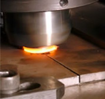
Figure 3: FSW typically uses a slight push angle
The FSW of hard metals (steel, Ti, Ni) has been made possible due to advancements in both tool design and tool materials. Tool material choices for AHSS applications include ceramic-based Polycrystalline Cubic Boron Nitride (PCBN) and refractory based Tungsten-Rhenium alloy (W-Re). PCBN is chosen because it is extremely wear resistant and has good thermal management. W-based material is chosen because it is very tough at room and welding temperatures and it is capable of being used for thick sections of steels.
Mechanical properties for FSW of AHSS cross-weld tensile specimens showed fully consolidated weld joints without discontinuities, but showed a drop-in weld ductility of about 10%, as seen in Figure 4.
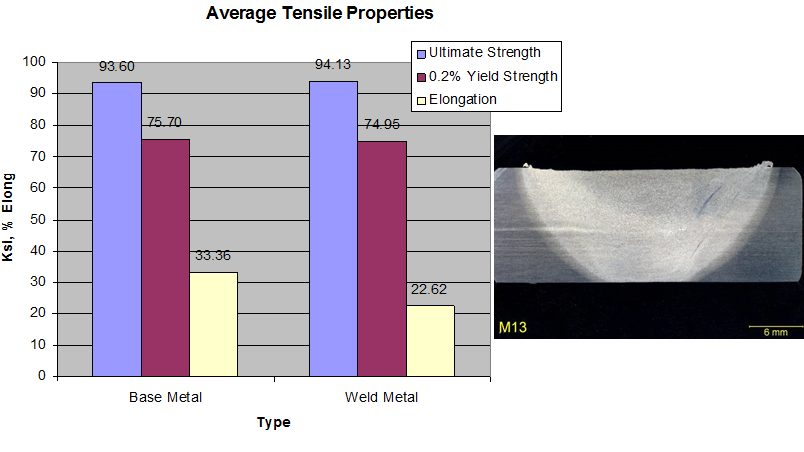
Figure 4: Mechanical properties of FSW for AHSS.
Friction Stir Spot Welding
A variation of the FSW process is Friction Stir Spot Welding. This process was specifically developed for some automotive applications, including joining of AAl), Al-to-steel, and AHSS. The process steps are similar to FSW without the linear movement, thus creating a “spot”-type joint (Figure 5).O-1
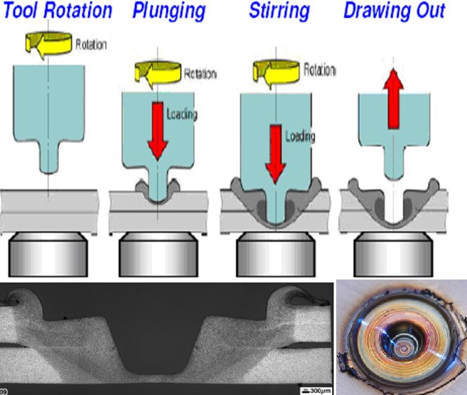
Figure 5: Process steps for friction stir spot welding (top) with the resultant weld profile (bottom).O-2
In summary, the advantages and limitations of friction welding processes are listed below.
- Advantages:
- No melting means no chance for solidification-related defects
- Filler materials are not needed
- Very few process variables result in a very repeatable process
- In the case of CD friction welding, can be deployed in a production environment
- Fine grain structure of friction welds typically exhibits excellent mechanical properties relative to the BM, especially when welding Al
- No special joint preparation or welding skill required
- Limitations:
- Equipment is very expensive
- Limited joint designs, and in the case of CD and inertia welding, parts must be symmetric
- FSW is very slow, and not conducive to high-speed