The Resistance Spot Welding (RSW) process is often used as a model to explain the fundamental concepts behind most resistance welding processes. Figure 1 shows a standard Resistance Spot Welding arrangement in which two copper electrodes apply force and pass current through the sheets being welded. If the sheets are steel, the resistance to the flow of current of the sheets will be much higher than the copper electrodes, so the steel will get hot while the electrodes remain relatively cool. But another important characteristic exists that is critical to most resistance welding processes – the contact resistance between the parts (or sheets) being welded. As indicated on the figure, the highest resistance to the flow of current is where the sheets meet (“Resistance” 4). This fact allows a weld nugget to begin forming and grow exactly where it is needed – between the sheets.
The figure depicts the flow of current from one electrode to the other as an electrical circuit that contains seven “resistors”. Resistors 1 and 7 represent the bulk resistance of the copper electrodes, Resistors 2 and 6 represent the contact resistance between the electrodes and the sheets, Resistors 3 and 5 represent the bulk resistance of the sheets, and Resistor 4, as mentioned, represents the contact resistance between the sheets. Another fact that works strongly in the favor of resistance welding of steel is that as the steel is heated, its resistivity relative to copper increases even more. So, the initial contact resistance effectively heats the surrounding area which is in turn heated more rapidly because its resistance is higher since it is hotter. As a result, heating and weld nugget formation can occur quite rapidly. A typical weld time for RSW of steel is approximately 1/5 of a second. The current required in resistance welding is much higher than arc welding, and it is in the range of 8-15 kA.
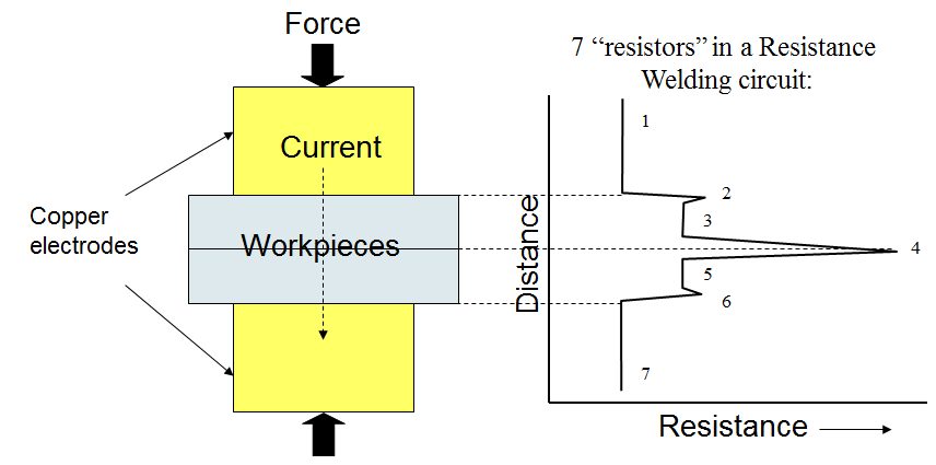
Figure 1: Resistances associated with steel Resistance Spot Welding.
Most welding processes produce welds that provide strong visible evidence of weld quality, so visual examination is often an important approach to verifying the quality of the weld. However, with most resistance welding processes visible examination is not possible due to the “blind” weld location between the sheets or parts being welded. As a result, maintaining weld quality with processes such as Resistance Spot Welding is highly dependent on what is known as a lobe curve (Figure 2), which is basically a process window for Resistance Spot Welding. The lobe curve represents ranges of weld current and time that will produce a spot weld nugget size that has acceptable mechanical properties for the intended application. So, weld quality monitoring with resistance welding processes relies highly on the ability to monitor parameters such as current and time. During production, if a weld is made with parameters that fall outside of the lobe curve, the weld is considered unacceptable. Ultrasonic testing is also often used in the automotive industry for Nondestructive Testing (NDT) of the blind location of Resistance Spot Welding.
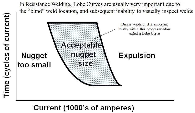
Figure 2: Resistance welding lobe curve.
RSW Electrode Geometry
Electrode geometry is a very important consideration with RSW. Figure 3 shows three common shapes, but there are many more options available including unique custom designs for specific applications. The basic electrode geometry is usually selected to improve the electrical-thermal-mechanical performance of an electrode. This is generally a geometry in which the cross-sectional area increases rapidly with distance from the workpiece, thereby providing a good heat sink. The choice of shape may also include considerations such as accessibility to the part and how much surface marking of the part is acceptable. The diameter of the electrode contact area is also a consideration. Too small an area will produce undersized welds with insufficient strength, while too large an area will lead to unstable and inconsistent weld growth characteristics.
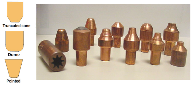
Figure 3: Typical RSW electrode geometries (left), example geometries used by automotive manufacturers (right).
Electrodes must be able to conduct current to the part, mechanically constrain the part, and conduct heat from the part. They must be able to sustain high loads at elevated temperatures, while maintaining adequate thermal and electrical conductivity. The choice of electrode alloy for a given application is often dictated by the need to minimize electrode wear. When electrodes wear, they typically begin to “mushroom”, or grow larger in diameter. Electrode wear is accelerated when there is an alloying reaction between the electrode and the part, a common problem when welding Aluminum (Al) and coated steels. As the electrode diameter increases, the current density decreases, resulting in a decrease in the size of the weld. Since the strength of a spot-welded joint is directly related to the size of the weld nugget, electrode wear can be a big problem.
A range of Copper (Cu)-based or refractory-based electrode materials are used depending on the application. The Resistance Welding Manufacturers Association (RWMA) sorts electrode materials into three groups: A, B, and C. Group A contains the most common Cu-based alloys (see Table 1), Group B contains refractory metals and refractory metal composites, and Group C contains specialty materials such as dispersion-strengthened copper. Within the groups, they are further categorized by a class number. The general rule of thumb is as the class number goes up, the electrode strength goes up but the electrical conductivity goes down. When electrical conductivity goes down, the electrode heats more easily, resulting in premature electrode wear. The choice of electrode material involves many factors, but generally higher strength electrodes will be selected when higher strength materials are being welded. It is also important that the electrical and thermal conductivities of the electrode are much higher than those of the material being welded.
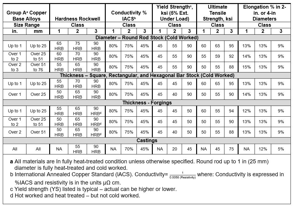
Table 1: Minimum mechanical and physical properties of Cu-based alloys for RWMA electrodes.A-18
The two most commonly used electrodes are the Class 1 and 2 electrodes of Group A. Class 1 electrodes [99% copper, 1% cadmium; 60 ksi UTS (forged); conductivity 92% International Annealed Copper Standard (IACS)] offer the highest electrical and thermal conductivity, and are typically used for spot welding Al alloys, magnesium alloys, brass, and bronze. Class 2 [99.2% copper, 0.8% chromium; 62 ksi UTS (forged), 82% IACS] electrodes are general-purpose electrodes for production spot and seam welding of most materials. IACS refers to a copper standard to which the electrodes are compared. Pure Cu has an IACS number of 100%.A-11, P-6, O-1