
Blog, homepage-featured-top, Joining Dissimilar Materials, main-blog
The discussions relative to cold stamping are applicable to any forming operation occurring at room temperature such as roll forming, hydroforming, or conventional stamping. Similarly, hot stamping refers to any set of operations using Press Hardening Steels (or Press Quenched Steels), including those that are roll formed or fluid formed.
Automakers contemplating whether a part is cold stamped or hot formed must consider numerous factors. This blog covers some important considerations related to welding these materials for automotive applications. Most important is the discussion on Resistance Spot Welding (RSW) as it is the dominating process in automotive manufacturing.
Setting Correct Welding Parameters for Resistance Spot Welding
Specific welding parameters need to be developed for each combination of material type and thickness. In general, the Hot Press (HP) steels require more demanding process conditions. One important factor is electrode force which should be higher for the HP steel than for cold press type steel of the same thickness. The actual recommended force will depend on the strength level, and the thickness of the steel. Of course, this will affect the welding machine/welding gun force capability requirement.
Another important variable is the welding current level and even more important is the current range at which acceptable welds can be made. The current range is weldability measurement, and the best indicator of the welding process robustness in the manufacturing environment and sometime called proceed window. Note the relative range of current for different steel types. A smaller process window may require more frequent weld quality evaluation such as for weld size.
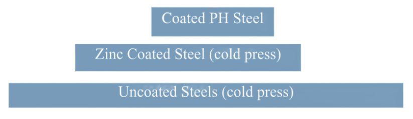
Relative Current Range (process windows) for Different Steel Types
The Effect of Coating Type on Weldability
In all cases of resistance spot welding coated steels, it is imperative to move the coating away from the weld area during and in the beginning of the weld cycle to allow a steel-to-steel weld to occur. The combination of welding current, weld time and electrode force are responsible for this coating displacement.
For all the coated steels, the ability of the coating to flow is a function of the coating type and properties, such as electrical resistivity and melting point, as well as the coating thickness.
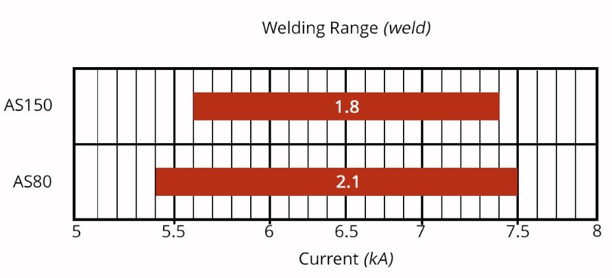
An example of cross sectioned spot welds made on Hot Press Steel with Aluminum -Silicon coating is shown below. It shows two coating thicknesses and the displaced coating at the periphery of weld. This figure also shows the difference in current range for the different coating thickness. The thicker coating shows a smaller current range. In addition, the Al-Si coating has a much higher melting point than the zinc coatings on the cold stamped steels, making it more difficult to displace from the weld area.
Hot Press Steel with Aluminum -Silicon
Liquid Metal Embrittlement and Resistance Spot Welding
Cold-formable, coated, Advance High Strength Steels such as the 3rd Generation Advanced High Strength Steels are being widely used in automotive applications. One welding issue these materials encounter is the increased hardness in the weld area, that sometime results in brittle fracture of the weld.
Another issue is their sensitivity to Liquid Metal Embrittlement (LME) cracking. These two issues are discussed in detail on the WorldAutoSteel AHSS Guidelines website and our recently released Phase 2 Report on LME.
Resistance Spot Welding Using Current Pulsation
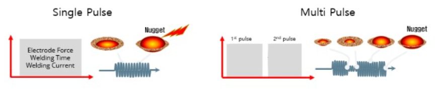
The most effective solution for the issues described above is using current pulsation during the welding cycle. A schematic description is shown below.
The pulsation allows much better control of the heat generation and the weld nugget development. The pulsation variables include the number of pulses (typically 2-4), the current level and time for each pulse, and the cool time between the pulses.
In summery, pulsation (and sometime current upslope) in Resistance Spot Welding proved to be beneficial for the following applications:
- Coated Cold Stamped steels
- Cold stamped Advance High Strength Steels
- Multi materials stack-ups – As described in our articles here on 3T/4T and 5T Stack-Ups

Thanks is given to Menachem Kimchi, Associate Professor-Practice, Dept of Materials Science, Ohio State University and Technical Editor – Joining, AHSS Application Guidelines, for this article.
Blog, homepage-featured-top, Joining, Joining Dissimilar Materials, main-blog, News, Resistance Spot Welding, Resistance Welding Processes, RSW Modelling and Performance, RSW of Dissimilar Steel
This blog is a short summary of a published comprehensive research work titled: “Peculiar Roles of Nickel Diffusion in Intermetallic Compound Formation at the Dissimilar Metal Interface of Magnesium to Steel Spot Welds” Authored by Luke Walker, Carolin Fink, Colleen Hilla, Ying Lu, and Wei Zhang; Department of Materials Science and Engineering, The Ohio State University
*****
There is an increased need to join magnesium alloys to high-strength steels to create multi-material lightweight body structures for fuel-efficient vehicles. Lightweight vehicle structures are essential for not only improving the fuel economy of internal combustion engine automobiles but also increasing the driving range of electric vehicles by offsetting the weight of power systems like batteries.
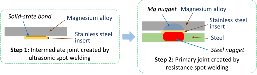
To create these structures, lightweight metals, such as magnesium (Mg) alloys, have been incorporated into vehicle designs where they are joined to high strength steels. It is desirable to produce a metallurgical bond between Mg alloys and steels using welding. However, many dissimilar metal joints form intermetallic compounds (IMCs) that are detrimental to joint ductility and strength. Ultrasonic interlayered resistance spot welding (Ulti-RSW) is a newly developed process that has been used to create strong dissimilar joints between aluminum alloys and high-strength steels. It is a two-step process where the light metal (e.g., Al or Mg alloy) is first welded to an interlayer (or insert) material by ultrasonic spot welding (USW). Ultrasonic vibration removes surface oxides and other contaminates, producing metal-to-metal contact and, consequently, a metallurgical bond between the dissimilar metals. In the second step, the insert side of the light metal is welded to steel by the standard resistance spot welding (RSW) process.
Cross-section View Schematics of Ulti-RSW Process Development
For resistance spot welding of interlayered Mg to steel, the initial schedule attempted was a simple single pulse weld schedule that was based on what was used in our previous study for Ulti-RSW of aluminum alloy to steel . However, this single pulse weld schedule was unable to create a weld between the steel sheet and the insert when joining to Mg. Two alternative schedules were then attempted; both were aimed at increasing the heat generation at the steel-insert interface. The first alternative schedule utilized two current pulses with Pulse 1, high current displacing surface coating and oxides and Pulse 2 growing the nugget. The other pulsation schedule had two equal current pulses in terms of current and welding time.
Lap shear tensile testing was used to evaluate the joint strength using the stack-up schematically, shown below. Note the images of Mg and steel sides of a weld produced by Ulti-RSW.
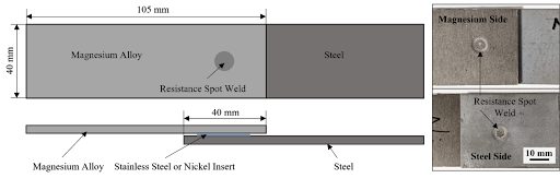 Lap Shear Tensile Test Geometry and the Resultant Weld Nuggets
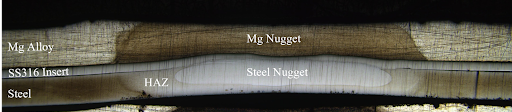
An example of a welded sample showed a distinct feature of the weld that is comprised of two nuggets separated by the insert: the steel nugget formed from the melting of steel and insert and the Mg nugget brazed onto the unmelted insert. This feature is the same as that of the Al-steel weld produced by Ulti-RSW in our previous work. Although the steel nugget has a smaller diameter than the Mg nugget, it is stronger than the latter, so the failure occurred on the Mg sheet side.
Joint strength depends on several factors, including base metal strength, sheet thickness, and nugget size, making it difficult to compare how strong a weld truly is from one process to another. To better compare the dissimilar joints created by different processes, joint efficiency, a “normalized” quantity was calculated for various processes used for dissimilar joining of Mg alloys to steels in the literature, and those results, along with the efficiencies of Ulti-RSW with inserts, are shown together below. Most of the literature studies also used AZ31 as the magnesium base metal. The ones with high joint efficiency (about 53%) in the literature are resistance element welding (REW) and friction stir spot welding (FSSW). In our study, Ulti-RSW with SS316 insert was able to reach an excellent joint efficiency of 71.3%, almost 20% higher than other processes.
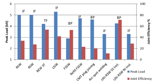 Process Evaluation and Comparison
Thanks are given to Menachem Kimchi, Associate Professor-Practice, Dept of Materials Science, Ohio State University, and Technical Editor – Joining, AHSS Application Guidelines, for this article.
Automotive Welding Process Comparison, Blog, Joining
Car body-in-white (BIW) structures, such as pillars and rails, are increasingly made of complex stack-ups of advanced high-strength steels (AHSS) for vehicle lightweighting to achieve improved fuel efficiency and crashworthiness. Complex stack-ups comprise more than two sheets with similar/dissimilar steels and non-equal sheet thicknesses.
Resistance spot welding (RSW) of complex stack-ups can be challenging, especially when a thin sheet of low-strength steel is attached to multiple thick AHSS sheets with a thickness ratio of five or higher (thickness ratio = total thickness of the stack-up/thickness of the thinnest sheet). In such a case, the heat loss is much faster on the thin sheet side than on the thick sheet side, and consequently, obtaining sufficient penetration into the thin sheet without expulsion on the thick sheet side can be challenging.
An example of two automotive applications involving complex AHSS steel stack-ups is shown below.
Examples of automotive applications involving complex AHSS steel stack-ups
For welding 2T steel stack-ups, the weld schedule may be relatively simple and utilize just one current pulse with a specific weld time. However, typical RSW machines and controllers can customize and precisely control each parameter indicated in Figure 1.
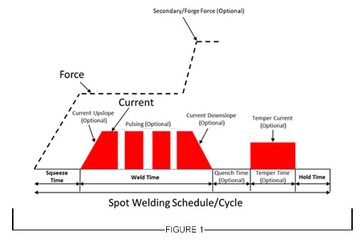
Figure 1: General Description of Resistance Spot Welding Schedule
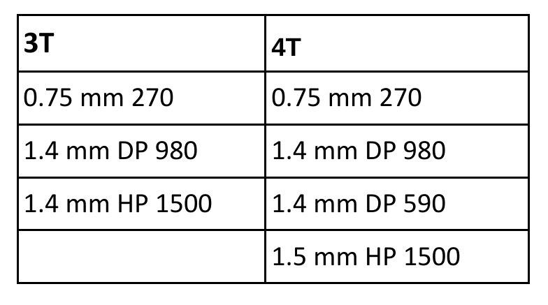
For RSW 3T and 4T applications, more advanced schedules are needed to achieve good weld nugget penetration through all the interfaces in the stack-up. To achieve this objective, the use of multiple current pulses with short cool time in between the pulses showed to be most effective, and in some cases, the application of a secondary force showed to be beneficial.
Figure 2 describes a method for joining the 3T stack-up using two current pulses. The first one is a short-time pulse that does not allow enough time for the electrode cooling to dominate at the top sheet, so a weld can easily form between the top and middle sheet. Once that nugget has formed, the second pulse utilizes a lower current and longer time to form the second nugget, which then grows into the first nugget to form a single weld.
This approach can be also used with electrode force variation during the welding cycle to provide additional control of the contact resistances, but of course, it is limited to machines that are capable of varying force during the weld cycle.
Typical pulse times are 50 – 350 ms with cool times of 20 – 35 ms and current levels between 8 – 15 KA, depending on materials type and thickness.
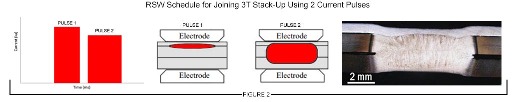
Figure 2: Example of RSW Schedule for Joining 3T Stack-Up Using 2 Current Pulses
A 4T stack-up example is shown in Figure 3. In this case, a similar approach was used with three current pulses applied during the weld cycle to produce a weld through all interfaces.
The common theme in resistance spot welding all complex stack-ups is using a complex, multi-pulse weld cycle. These more complex schedules should be developed experimentally and potentially with computational modeling. Another consideration that may be beneficial in some cases is to vary the top and bottom electrode face diameter, such as that the smaller electrode face is on the thinner material side of the stack-up.
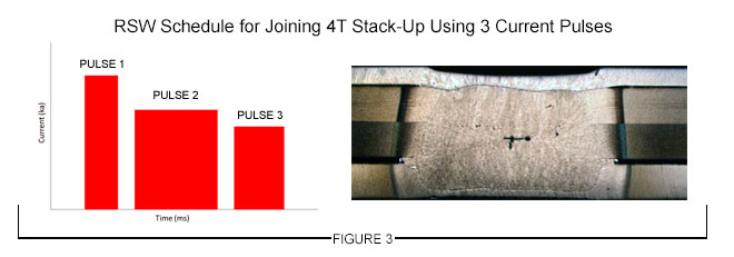
Figure 3: Example of an RSW Schedule for Joining 4T Stack-Up Using 3 Current Pulses
Thanks is given to Menachem Kimchi, Associate Professor-Practice, Dept of Materials Science, Ohio State University and Technical Editor – Joining, AHSS Application Guidelines, for this article.
Citations
Citation:
L-17. Y. Lu, E. Mayton, H. Song, M. Kimchi, W. Zhang, Dissimilar metal joining of aluminum to steel by ultrasonic plus resistance spot welding – Microstructure and mechanical properties, Mater. Des. 165 (2019) 107585. doi:10.1016/j.matdes.2019.107585.
Citations
Citation:
L-15. Y. Lu, A. Peer, T. Abke, M. Kimchi and W. Zhang, “HAZ Softening of Resistance Spot Welded 3T Dissimilar Steel Stack-up and Weld Nugget Penetration of a Four-Sheet Resistance Spot Welding AHSS,” Welding Journal, November 2019, Vol. 98.