Friction is a restraining force that limits metal flow resulting from contact with another surface during sheet forming. Friction is influenced by the complex interaction between the sheet steel, lubricant, and tooling material, as well as many parameters of the forming system, some of which are shown in Figure 1.

Figure 1: Friction is influenced by the complex interaction between the sheet steel, lubricant, and tooling material, as well as many parameters of the forming system. (image modified from Citation K-13)
Friction changes throughout the stamping process as well as across the part, since there are changes in contact pressure, contact temperature, geometry, the sheet steel strength (work hardening), and even the sheet metal surface due to flattening of the peaks after flowing over beads and radii. There is no one friction value that applies to all geometries and forming scenarios that can be encountered.
Characterizing friction in a simulative test is similarly challenging, since there is no one simulative test that approximates all regions of an engineered stamping. For many years, tooling, design, and simulation engineers used one friction value for each galvanized coating / lubricant combination, and applied that value across every part stamped from that metal with that lubricant. The industry has evolved to using different tests to generate friction values appropriate for different forming conditions.
Simulative tests to characterize friction include test to reflect bending under tension, pulling through draw beads, and movement over flat surfaces. Depending on the test, it may be possible to evaluate the effect of tooling material, temperature, radii, and speed in order to better simulate production conditions. Figure 2 indicates which of these simulative tests apply to the regions of an in-process stamping. The value obtained in one test is a function of only those specific test conditions and should not be compared against values obtained in other tests.
- Bending Under Tension test: In the Bend Under Tension (BUT) test, a metal strip is drawn over a fixed cylindrical pin with a pair of independently controlled hydraulic actuators offset by 90 degrees. Two load cells measure the pulling force and back tension force. (Figure 3)
- Draw Bead test: Two sets of tests are done using a Draw Bead Simulator (DBS). In the first test, the force to pull sheet steel through a set of fixed draw beads is measured and reflects both the bending and unbending forces as well as the friction forces. Another sample is pulled through frictionless roller beads in a similar arrangement. Here, only the bending/unbending forces are active. Subtracting the results allows for determination of the forces due solely to friction. (Figure 4)
- Strip Draw: In the Strip Draw test, friction is determined by pulling sheet steel through opposing flat platens. The restraining condition is controlled by the force applied on the flat platens. The influence of bending is not considered in this test. (Figure 5)
Other tests are also used to provide some assessment of formability. Dome Testing simulates stretch forming conditions and can provide a relative comparison between different materials and lubricants. The Twist Compression Test (TCT) is used to compare the performance of different lubricants under controlled, repeatable conditions. Lubricant breakdown, which results in adhesion between the tool and the sheet steel, can be evaluated in the TCT.

Figure 2: Pertinent Simulative Tests During Stamping (image modified from Citation S-42)

Figure 3: The Bending Under Tension Test (image modified from Citation S-42)
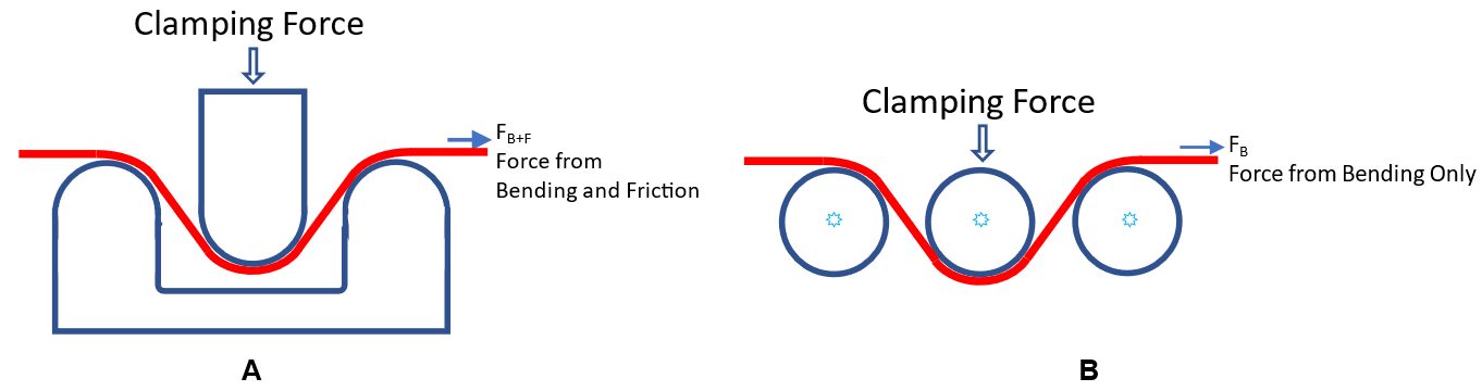
Figure 4: Draw Bead Simulator Testing determines the effect of friction from the differences in pulling force in two test conditions.
a) The strip pulled through fixed draw beads experiences restraining forces due to bending/unbending as well as forces due to friction.
b) The strip pulled through frictionless roller beads experiences restraining forces due only to bending/unbending.

Figure 5: The Strip Draw Test (image modified from U-6)