Tube hydroforming creates complex shapes by using internal pressure to expand a tube against a die cavity. Frame rails, engine cradles, roof rails and bows, instrument panel beams, cross members, pillars, and seat frames are among the parts created using hydroforming. Benefits of this approach can include part consolidation, weight reduction, improved stiffness and strength, tighter dimensional tolerances, fewer secondary operations, and reduced cost compared with conventional stamping and welding approaches.
These benefits are highlighted in a truck front end structure shown in Figure 1, where hydroforming allowed for consolidation of 31 parts into 18, and resulted in a 31% weight reduction. M-67
Automotive body structures have incorporated hydroformed parts for several years, with recent vehicles using AHSS grades to improve crash energy management and impact performance. Some specific examples:
The hydroformed A-Pillar on the 2015 Mustang Convertible (Figure 2) distributes impact loads to the windshield header and the hinge pillar.M-16
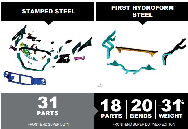
Hydroforming facilitates part consolidation and weight reduction relative to a stamped truck front end structure.M-67

Figure 2: 2015 Mustang Convertible: A-Pillar.M-16
The Door-to-Roof Support on the 2016 Nissan Titan XD (Figure 3) extends from the rocker/hinge pillar through the A-pillar and almost to the B-Pillar. Hydroforming this part from a Dual Phase Steel with 980MPa minimum tensile strength allowed for 25% section strength improvement allowing for thinner material at the same performance level. T-18, L-18

The hydroformed Upper Load Beams of the 2017 Chrysler Pacifica (Figure 4) saved 1.8 kg per vehicle compared with a conventional approach.T-19

Figure 4: 2017 Chrysler Pacifica: Upper Load Beams.T-19
Each of the two hinge pillars on the 2019 Jeep Wrangler (Figure 5) contain 2 hydroformed tubes made from TRIP 400/690.B-8

Figure 5: 2019 Jeep Wrangler: Hinge Pillars.B-8
Tube hydroforming, as the name suggests, starts with a linear-welded tube, produces either with high frequency induction welding or laser welding. The tube is then bent to the general shape, and a pre-forming operation helps to put steel in the optimal position. After placing the preformed tube in the hydroforming die, end-plugs create a seal for subsequent internal pressurization. Figure 6 shows the changes to tube shape along the process of producing the hydroformed roof rails from DP800/1000 for the 2015 Ford Edge.H-13

Figure 6: Shape evolution to achieve a hydroformed roof rail from DP 800/1000.H-13
If the hydroforming process does not result in a change in the length of the pre-formed tube, then the only change is an increase in the local section diameter. This corresponds to a strain state of plane strain, which is the strain path associated with the greatest risk of cracks. Mounting the end-plugs on actuators allows for application of axial loads on the ends of the tube as the internal pressure changes. End feeding in this manner changes the strain state favorably, creating compression in the axial direction as the tube diameter stretches. With axial feeding, the strain state near the ends move to the left hand side of the Forming Limit Diagram, allowing for higher strains to be reached prior to failure – meaning that more complex shapes can be created. Away from the tube ends, the axial feeding has limited effect, so plane strain formability (the lowest point on the Forming Limit Curve) limits the product shape.
Formability is further limited compared with the incoming sheet, since the rolling, welding, sizing, bending, and pre-forming operations all decrease the available ductility prior to hydroforming. Understanding the effect of each operation which changes the strain and thickness in the tube allows for small process changes which may help to improve the amount of residual ductility for the subsequent tube hydroforming operation. The strains generated from each step results in the work hardening of the sheet steel, leading to an increase in strength and decrease in ductility.
Product and tool designs must account for these increased strengths and reduced formability parameters. The deformation available for the pre-form bend process and the subsequent hydroforming process will depend on the material selected, tube D/T ratio, tube manufacturing process, centerline radius of the pre-form bend, and the included angle of the bend. Tubes of higher strength AHSS will have limited elongation available. Avoid exceeding the available total elongation for bending limits or forming limits – especially in the work hardened areas of the pre-form bends. Refer to Figure 4 in the Tube Bending article for anticipated elongation values for several illustrative high strength steels formed into tubes of various D/T ratios.
The hydroforming process for tubes usually involves expanding the tube diameter from 3% to 30% depending on the design, materials selected and pressures available for forming. Tube production commonly utilizes one of three basic methods of hydroforming tubes, categorized by the internal pressure used for the expansion.
In high-pressure tube hydroforming (Figures 7 and 8), the tube is placed in the die and the die is closed. Pressurizing the tube now causes the metal to stretch as the circumference increases to conform to the inner circumference of the die – often with tight radii in corners and product features. Higher strength steels may be unable to expand sufficiently to fill the die geometry or create small radii without failure. Furthermore, high pressure could be necessary to obtain the correct geometry with minimum springback or fewer wrinkles compared to low-pressure hydroforming.

Figure 7: Schematic of High Pressure Hydroforming, courtesy of ANDRITZ Schuler Inc.
Figure 8: Animation of High Pressure Hydroforming, courtesy of ANDRITZ Schuler Inc.
Pressure Sequence tube hydroforming (Figures 9 and 10) begins with a tube whose circumference is slightly less than the final circumference of the finished geometry. Tube pressurization occurs after placing the tube in an open die, prior to closing. As the die closes, the circumference of the tube changes shape to conform to the closing die. The internal pressure is sufficient to prevent the tube from buckling during the shape change. A small circumference increase combined with a uniform wall thickness means that high strength and lower-formability metals can achieve tighter radii without failure. Pressure Sequence Hydroforming is suitable for tubes made from AHSS. This approach results in a change of the shape of the tube cross-section, rather than tube expansion. Hydroforming simulation with commercially available programs is beneficial to optimize the pressurization sequence.

Figure 9: Schematic of Pressure Sequence Hydroforming, courtesy of ANDRITZ Schuler Inc.
Figure 10: Animation of Pressure Sequence Hydroforming, courtesy of ANDRITZ Schuler Inc.
Enhanced circumferential expansion can be achieved by incorporating end feeding. Special end pistons push additional material into the die cavity from the tube end to provide more material for higher expansion of the tube circumference. This method of tube circumference expansion involves bi-directional strain. The end feeding is beneficial for hydroforming tubes from AHSS. Note that excessive end-feeding may increase the pressure required to form small corner radii.S-43
To assist with pre-production process and die design, computerized forming-process development is an excellent tool for examining the validity of applying different AHSS to potential part designs. However, proper inputs are critical: hydroforming tubes made from advanced high strength steels require highly developed forming limit curves generated which consider different tube D/T ratios, degrees of pre-form bend, and final geometrical shape. Each step as the straight tube is converted to a hydroformed part represents a non-linear strain path, which increases the importance of using the proper Forming Limit Curve. The FLC generated for the initial sheet steel will give a false indication of the available formability since it does not account for the impact of the forming steps prior to hydroforming.
An example of the material property changes from tube creation comes from Figure 11, which compares 1.88 mm thick mild steel (labeled as DDQ), HSLA 350/450, and DP 350/600 formed into a 76.2 mm (3 inch) diameter tube. Figure 11 shows the summary of average properties for the three steels. The much larger jump associated with tube forming of the dual phase steel grade is associated with the higher n-value of this product.

Figure 11: Strength Comparison on samples taken from the flat sheet and after tube forming.S-43
For trimming and piercing, the same general cautions utilized for stamped AHSS parts apply to hydroformed AHSS parts. Since Advanced High Strength Steels have higher tensile strength than conventional high-strength steels, engineering the trim tools to withstand higher loads is a requirement. Proper support for the trim stock during the trim operation will minimize edge cracking. Laser trimming, which is common for hydroformed parts, is still an excellent choice. However, the trimmed edge may see some hardening associated with the local heating and cooling from the laser beam.
Design Considerations
In general, the same design guidelines that support hydroforming of conventional steels apply to AHSS. However, consideration of part function and the available elongation for forming is necessary during development of the part design and manufacturing processes.
- Hydroforming tools need to be stiff and rigid in all directions, or else there is the risk of deviation from the targeted.
- Springback and shape distortion is more likely on longer tubes made from thinner sheet steels. Tight bending radii on higher strength steels increases the risk of springback. The tube diameter to wall thickness (D/t) ratio, cross section shape, forming process (bending, preforming method, hydroforming parameters) also affects springback.
- Pierce holes in the tube by cutting against the water pressure.
- Place welds in areas with low forming strains.
- The cross section can change, but the circumference should stay the same to minimize cracks.
- Avoid sharp radius/thickness due to forming forces.