A-80
A-80. Auto/Steel Partnership. (2008) “Future Generation Passenger Compartment Phase 1 Report Executive Summary,” Available from https://a-sp.org/wp-content/uploads/2020/08/Future-Generation-Passenger-Compartment.pdf
A-80. Auto/Steel Partnership. (2008) “Future Generation Passenger Compartment Phase 1 Report Executive Summary,” Available from https://a-sp.org/wp-content/uploads/2020/08/Future-Generation-Passenger-Compartment.pdf
Citation:
A-80. Auto/Steel Partnership. (2008) “Future Generation Passenger Compartment Phase 1 Report Executive Summary,” Available from https://a-sp.org/wp-content/uploads/2020/08/Future-Generation-Passenger-Compartment.pdf
Citation:
A-79. Auto/Steel Partnership (2005). “Lightweight Front End Structure Phase 1 & 2 Final Report,” Available from https://a-sp.org/wp-content/uploads/2020/08/Lightweight-Front-End-Structures.pdf
The transportation industry’s contribution to greenhouse gas (GHG) emissions and global warming is well documented and understood. Vehicle OEMs, fleet operators, and transport users all have responsibilities to reduce environmental impacts on the planet and contribute to meeting global emissions regulations.
Mobility as a Service (MaaS) solutions like WorldAutoSteel’s flaghip Steel E-Motive (SEM) program have the potential to contribute to a reduction in GHG emissions, helping to achieve these global targets and specific policy objectives. The Steel E-Motive engineering report, released in 2023, addresses the impact of emissions reduction using Life Cycle Assessment, with key results summarized in this article.
Life Cycle Assessment (LCA) is a methodology that evaluates the environmental impact of a product across its entire lifecycle. By understanding the impact across the entire vehicle life cycle, vehicle manufacturers evaluate trade-offs and assess the net impact of the product they’re using.
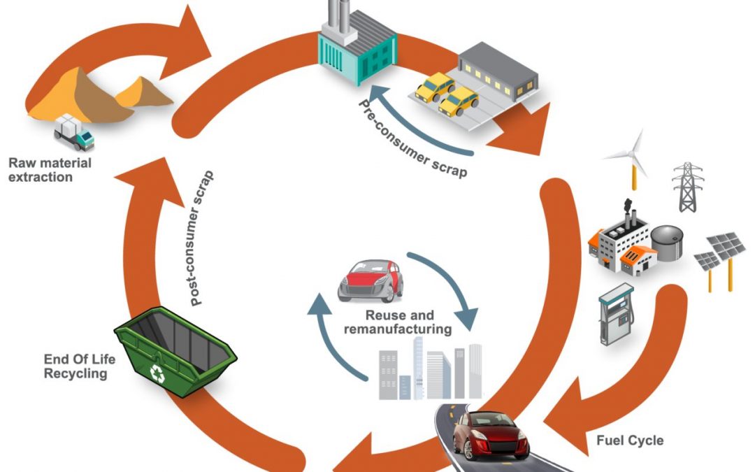
Cradle-to-grave assessments utilize a boundary that includes impacts from the production phase (including raw material extraction and vehicle production), the use phase (including fuel or electricity as well as consumables like tires and fluids) and the end-of-life phase, which could include disposal and/or recyling of the product, as shown in Figure 1. We applied LCA throughout the development of the SEM concept.
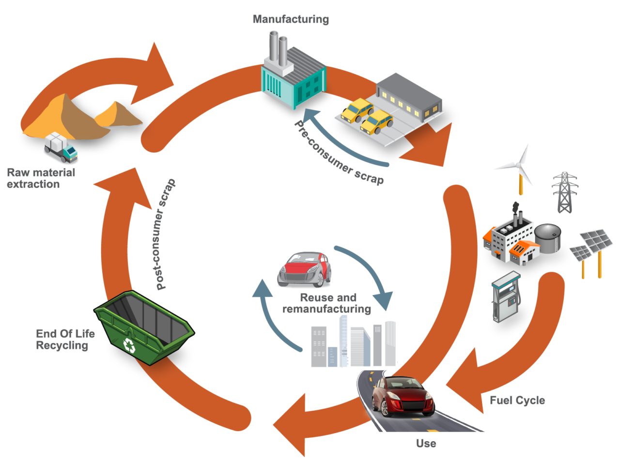
Figure 1. SEQ Figure \* ARABIC 1 Life Cycle Assessment, considering the entire life of the vehicle, from raw material extraction to end of life
LCA can cover a range of environmental impacts; however, for the SEM program, we focused on GHG emissions through the GWP-100 indicator and total energy consumption using Cumulative/Primary Energy Demand and Fossil Energy Consumption indicators.
A key consideration in LCA calculations is establishing an appropriate reference vehicle. For this program, the following criteria was used:
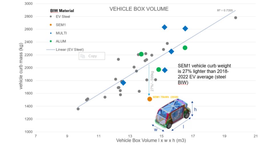
Figure 2. Vehicle curb weight versus box volume comparison. Reference vehicle data; source www.a2mac1.com
SEM vehicle life cycle calculations assume a hypothetical 2030 manufacture and start-of-operation date of 2030 to 2035. We updated the electricity grid supply mix to include the average of the International Energy Agency (IEA) scenario estimates for 2030 and 2040.
Figure 3 below highlights absolute calculated life cycle GHG emissions, in units of kgCO2e/ passengerꞏkilometer studied, with the individual contributions of vehicle manufacturing, vehicle use, and end-of-life phase presented.
The analysis evaluated two reference/baseline conditions and nine SEM sensitivity studies, see Figure 4. These included alternative assumptions on LCA end-of-life modeling methodology, lifetime vehicle activity (and battery lifetime), alternative operational energy consumption sensitivities, sensitivities on the use of ‘green’ steel, and vehicle occupancy rates.
The accompanying pie chart shows the breakdown and contributions to the vehicle manufacture GHG for the baseline SEM scenario (2).
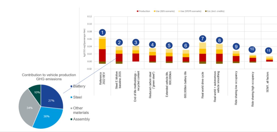
Figure 3. SEQ Figure \* ARABIC 2 life cycle assessment GHG results
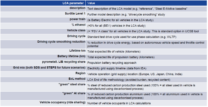
Figure 4. Reference/baseline conditions and SEM sensitivity studies
Based on the parameters outlined, applying LCA to SEM concept demonstrated the designs’ potential to reduce lifecycle greenhouse gas emissions by up to 86 percent compared to a present-day battery electric vehicle operating as a taxi.
This potential can be realized by adopting the following measures:
The projected net GHG emissions for the SEM vehicle operating with the flexibilities described above already represent a significant reduction when compared to the current baseline.
Achieving net zero emissions would require additional measures like offsetting manufacturing impacts (e.g., through compensatory credits from atmospheric carbon capture and storage) and transitioning to a 100 percent renewable electricity grid.
Taking a Life Cycle Assessment approach to the SEM concept demonstrates the possibilities for engineering future mobility vehicles that continue to move us closer to a net zero future. For more information about the Steel E-Motive program, download the engineering report here: https://bit.ly/SEM_Eng_Report

Thanks go to Russ Balzer for his contribution of this article to the AHSS Insights blog. As.technical director at WorldAutoSteel, he leads technical programs and oversees the organization’s work in research, modeling, and advocacy for Life Cycle Assessment in the automotive sector. An LCA Certified Professional through the American Center for Life Cycle Assessment (ACLCA), he also acts as the WorldAutoSteel liaison to the worldsteel LCA Expert Group.
The Steel E-Motive battery modules, cooling plates & hoses, electrical connectors, and battery management system are mounted to an AHSS carrier frame. This assembly is then bolted to the body structure. The body in white floor assumes the role of the battery top cover, providing both cost and weight savings; an AHSS bottom cover seals and provides underbody protection.
You can view the details about the SEM1 final battery concept in section 7.3 in the SEM Engineering Report: https://bit.ly/SEM_Eng_Report
The Steel E-Motive Battery Carrier Frame
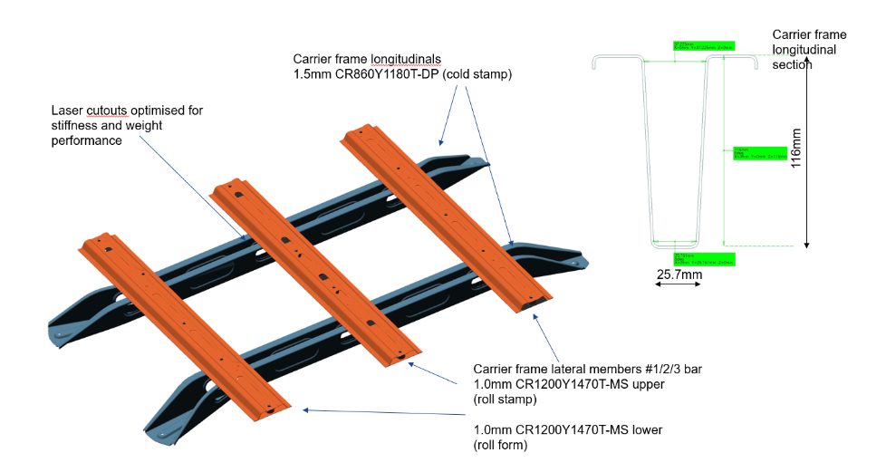
The battery carrier frame forms an integral part of the body structure load path. It connects to the front and rear longitudinals and the floor cross members. Two different manufacturing approaches and designs were considered for the longitudinals.
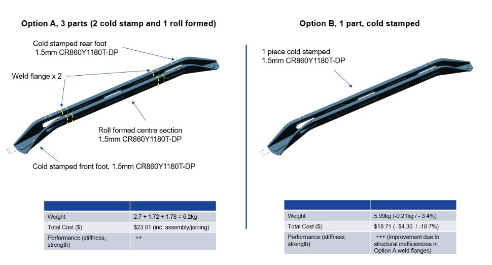
Option A considered a 3-part longitudinal design, with unique cold stampings for the front and rear “feet” and a roll-formed center section. The part integration is accomplished via an overlap weld flange and spot welding. Dual Phase 1180MPa UTS grade AHSS was selected based on the strength required for crash load reaction and enabling a lower 1.5mm gauge thickness. Initially, it was perceived that the roll-formed center section design would enable an overall lower-cost solution.
Option B replaces the 3-piece design with a single, cold-stamped part, again using 1.5mm DP1180 AHSS. The deep draw profile and material’s low ductility presented formability challenges for the cold stamping of the longitudinal. These were overcome by adjustments to the deep draw profile and optimization of the die and stamping parameters.
A comparison of the two designs shows that a small weight saving and a significant cost reduction of $4.30 (18.7%) per longitudinal is achieved with the single cold-stamped design. The vehicle NVH, static stiffness, and crash performance were also calculated to be superior for the integrated design Option B.
Therefore, Option B, provides cost, weight, and performance benefits compared to the multiple part design Option A.
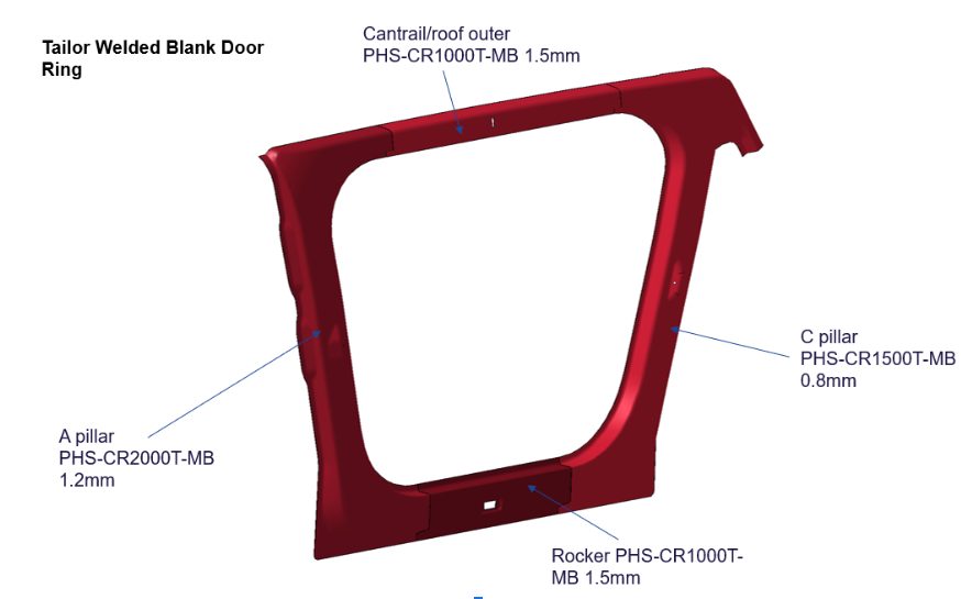
Part integration via laser-welded blanks allows different steel grades, thicknesses, and coating types to be combined into a single blank before the fabrication process. The Steel E-Motive door ring is a hot-formed part consisting of four different blanks with different AHSS grades and thicknesses.
The performance requirements for the specific region determine the grades and thicknesses for each blank. The A-pillar requires very high strength to protect the front occupants in the event of a high-speed frontal or side collision. Lower strengths and grades are required for the rocker, cantrail, and C-pillar parts. The four blanks are cut from the native material grade coil and joined using laser welding to form the single-door ring blank. This then undergoes a hot-forming process to achieve the design door ring shape and the Ultra High-Strength properties of press-hardened steel.
Consolidating four blanks into a single part significantly reduces scrap compared to a single blank part, and simplifies part manufacturing by eliminating other stamping and assembly processes with related cost savings. Higher material utilization means less steel is produced, resulting in lower costs and lower GHG emissions. The laser weld between the blanks helps achieve greater strength and stiffness to spot-welding four individual blanks.
The latest AHSS grades and fabrication processes allow engineers to reduce the number of parts or blanks used in automotive body structures. Several part integration and consolidation processes have been applied and demonstrated in the Steel E-Motive concept. Part consolidation results in lower scrap rates, improved material utilization, reduced part cost, and GHG emissions. The integrated structures also improve overall stiffness and strength performance.

Thanks go to Neil McGregor for his contribution of this article to the AHSS Insights blog. As Chief Engineer, Systems Integration at Ricardo, Neil has extensive knowledge of lightweight, advanced materials across all major vehicle sub-systems and leads the Steel E-Motive vehicle engineering program at Ricardo.
High-volume automotive body structures using Advanced High-Strength Steel (AHSS) grades offer the potential for low cost and weight, high strength performance, and competitive life-cycle and sustainability attributes.
Reducing the number of individual parts within an automotive body structure can yield further cost, weight, and sustainability benefits without compromising performance.
WorldAutoSteel’s latest engineering demonstrator project, Steel E-Motive, delivered a clean-sheet body structure concept for a fully autonomous Mobility as a Service vehicle. The body structure design features components and sub-assemblies where the number of individual parts (i.e., stampings) have been reduced by applying fabrication methods such as hydroforming and tailor welded blanks, combined with the latest AHSS grades such as Press Hardened/Hot Formed and 3rd generation/Retained Austenite grades.
Integrating multiple body structure parts yields more efficient material utilization (reduced scrap), enabling cost & weight reduction, structural performance improvement, and life-cycle Greenhouse Gas (GHG) benefits.
Some examples of steel body structure part integration applied to the Steel E-Motive concept design follow:
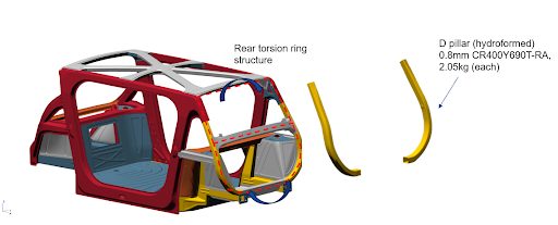
Tube hydroforming enables the creation of complex geometries by using internal pressure to expand a tube against a die cavity. The result is a single tubular component with no weld flanges, offering uniform properties with higher overall strength and stiffness than a component fabricated (i.e., welded) from multiple parts. Hydroformed parts have high material utilization rates (low scrap), giving good cost and weight efficiency. The Steel E-Motive body structure features hydroformed tubes for the B and D pillars.
The B pillar acts as one of the main structural members protecting the vehicle occupants and propulsion battery in the event of a high-speed side impact collision. Crash simulations demonstrate that the Steel E-Motive SEM1 vehicle has the potential to achieve IIHS “good” (highest) side crash rating, and the battery is well protected in the event of a collision. Steel E-Motive B pillars are positioned on the closing edges of the front and rear side closures. In the event of a high-speed side collision, the B pillar section profiles ensure that both B pillars deform, contact, and combine to produce an effective box section that reacts to the side impact crash loads, minimizing intrusion.
A compact and efficient section profile enables overlapping and interlocking features and maximizes the windows’ size, enhancing occupants’ visibility. Tube hydroforming enables the achievement of such complex geometric profiles. A TRIP690 (CR400Y690T-RA) grade AHSS was selected for the B pillars. Its high yield and UTS strength deliver side crash performance, and up to 25% elongation enables the complex geometry profiles to be achieved.
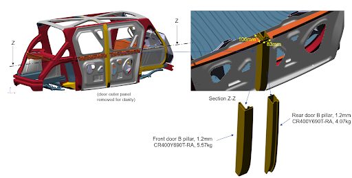
The hydroformed tube approach for the Steel E-Motive B pillars has enabled an integrated part solution, with a 10-15% cost and weight saving compared to a cold stamped and spot welded design.
The Steel E-Motive D pillars are an integral part of the rear torsion ring structure, which significantly contributes to the static and NVH torsional stiffness of the BIW structure. The tube hydroformed D pillars effectively enable 2 to 3 cold stamped and spot-welded parts to be integrated into a flange-less single component, achieving higher overall stiffness, improved material utilization, and improved overall performance.
The hydroformed D pillars of the Steel E-Motive BIW are another example of part efficiency and integration, providing cost, weight, and performance benefits.
Find further details on tube hydroforming using steel: https://ahssinsights.org/forming/hydroforming/hydroforming/
The newest AHSS grades and fabrication techniques enable engineers to streamline automotive body structures by reducing the number of parts or blanks needed. The Steel E-Motive concept showcases several successful part consolidation processes, which lead to lower scrap rates, better material utilization, reduced costs, and decreased GHG emissions. Additionally, these integrated structures enhance overall stiffness and strength.
Thanks go to Neil McGregor for his contribution of this article to the AHSS Insights blog. As Chief Engineer, Systems Integration at Ricardo, Neil has extensive knowledge of lightweight, advanced materials across all major vehicle sub-systems and leads the Steel E-Motive vehicle engineering program at Ricardo.