Blog, homepage-featured-top, main-blog
Efficient energy and resource use in automotive engineering is a major challenge that can only be overcome with innovative solutions. A cost-effective and resource-saving approach is the use of digital methods in production.
In demanding production chains like body-in-white components from tailor-welded blanks (TWBs), it is crucial to digitally simulate the product before actual production to prevent tool adjustments and unnecessary trials. A new digital twin for the tailor welded blanking process chain links numerical simulations for welding and forming steps. Figure 1 shows a typical application for a tailor welded blank component in the body in white: front longitudinal member.
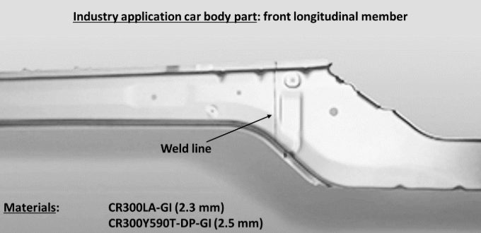
Figure 1: A typical application for TWBs in the automotive industry is the longitudinal member shown here at the front. The TWB shown consists of micro-alloyed CR300 LA (2.3 mm) and high-strength dual phase steel with 600 MPa (2.5 mm). The welded sheet metal blanks were deep-drawn into the final shape of the TWB.
The process chain of laser beam welding and deep drawing faces challenges when pushing to stronger advanced high-strength steels. Areas around the weld seam are susceptible to softening due to heat input during welding, leading to changes in material properties, such as decreased strength in the heat-affected zone (HAZ) and hardening of the weld metal, influencing forming limit behavior.
Adapted welding process control can optimize material properties, ensuring laser beam welding’s applicability for AHSS grades. Consistent digital simulation of manufacturing processes is one of the most promising approaches for enabling low-emission, lightweight construction and maximizing material efficiency. To replace material-intensive experiments, simulations using the finite element analysis (FEA) create a virtual 3D model of a component.
Welding structure simulation validation is performed using thermocouple measurements and metallographic sections. The core of the forming simulation consists of material cards for high-strength steels. Yield curves, stress-strain curves, and forming limit diagrams are incorporated into the simulation. Validation experiments complete the forming simulation setup, comparing the deep-drawing press force-displacement curve with the modeled curve. The deep-drawn component is then digitized using a 3D scanner, allowing comparison of the real component with the simulated one in terms of geometry, defects, and sheet thickness. Figure 2 shows a simulated S-rail as demonstrator component after deep-drawing simulation.
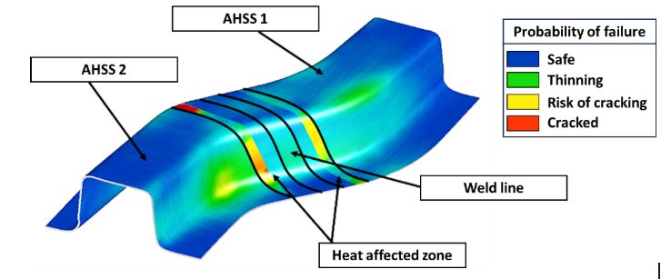
Figure 2: Simulation result of an S-rail formed from TWBs for the probability of failure (max. failure). Both the weld seam and the heat-affected zone are greatly oversized in the illustration for better visibility. The base materials are two high-strength steels of different sheet thicknesses, which were welded together using a butt joint. The heat-affected zone is represented as two areas with different properties.
Today’s forming simulation tools cannot readily account for the small geometric areas of weld metal and heat affected zones, hence the welding simulation results cannot be directly used as input for another software. In addition, it is difficult to measure material behavior of the welding zones to correctly model them in forming simulations. New interfaces were developed for a digital data management platform to bridge this gap. Intermediate steps are required to transfer welding results to forming simulation, including determining the heat-affected zone and deriving weld seam geometry. The analysis chain of the digital twin involves extracting welding simulation results, creating input for forming simulation and adjusting welding simulations based on forming results in an iterative loop. Figure 3 illustrates the digital process chain.
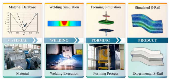
Figure 3: Scheme of the digital (top) and conventional (bottom) process chain of tailor welded blanking: main process steps from material to final product.
Linking welding and forming simulations (Figure 4) enable TWBs made of advanced high-strength steels reach higher strength levels, ultimately saving resources in car body construction and making production more sustainable. The development of TWBs for automotive construction serves as a starting point for expanding lightweight construction potential across the transport sector.
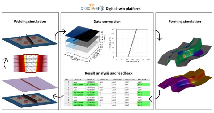
Figure 4: Bidirectional digital twin: How adapting welding simulation closes the loop. The welding simulation displays its results using three-dimensional volume elements. With the help of the digital platform, a simplified two-dimensional representation is generated that contains information about the position of the weld seam and heat-affected zone, which can then be modelled in shell elements. This data is used for the forming simulation and the result is fed back into the digital platform. The parameters of the best simulation results are highlighted and assist in the planning of new welding simulations.

A special thank you to our author, Josefine Lemke, M. Sc. She is a research associate at Fraunhofer IPK in Berlin, Department Joining and Coating Technology. She specialized in additive manufacturing and welding simulation. The focus is on the correlation of component quality and powder properties, particularly in the context of industry and SME environments. She is also working on the qualification of ultra-high-strength steels in car body construction (integration of laser welding and forming simulation in tailor-welded blanking).
Blog, homepage-featured-top, main-blog, News, Resistance Spot Welding, RSW of Dissimilar Steel, Tool & Die Professionals
Urbanization and waning interest in vehicle ownership point to new transport opportunities in megacities around the world. Mobility as a Service (MaaS) – characterized by autonomous, ride-sharing-friendly EVs – can be the comfortable, economical, sustainable transport solution of choice thanks to the benefits that today’s steel offers.
The WorldAutoSteel organization is working on the Steel E-Motive program, which delivers autonomous ride-sharing vehicle concepts enabled by Advanced High-Strength Steel (AHSS) products and technologies.
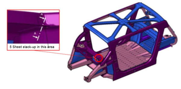
The Body structure design for this vehicle is shown in Figure 1. It also indicates the specific joint configuration of 5 layers AHSS sheet stack-up as shown in Table 1. Resistance spot welding parameters were developed to allow this joint to be made by a single weld. (The previous solution for this welded joint is to create one spot weld with the bottom 3 sheets indicated in the table and a second weld to join the top 2 sheets, combining the two-layer groups to 5T stack-up.)
NOTE: Click this link to read a previous AHSS Insights blog that summarizes development work and recommendations for resistance spot welding 3T and 4T AHSS stack-ups: https://bit.ly/42Alib8
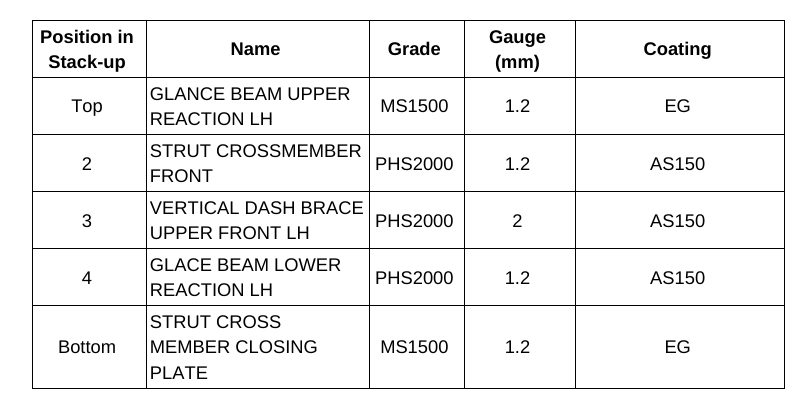
Table 1. Provided materials organized in stack-up formation showing part number, name, grade, gauge in mm, and coating type. Total thickness = 6.8 mm
The same approach of utilizing multiple current pulses with short cool time in between the pulses was shown to be most effective in this case of 5T stack-up. It is important to note that in some cases, the application of a secondary force was shown to be beneficial, however, it was not used in this example.
To establish initial welding parameters simulations were conducted using the Simufact software by Hexagon. As shown in Figure 2, the final setup included a set of welding electrodes that clamped the 5-layer AHSS stack-up. Several simulations were created with a designated set of welding parameters of current, time, number of pulses, and electrode force.
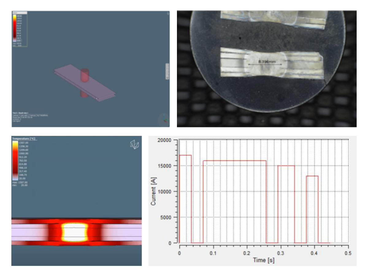
Figure 2. Example of simulation and experimental results showing acceptable 5T resistance spot weld (Meets AWS Automotive specifications)

Thanks is given to Menachem Kimchi, Associate Professor-Practice, Dept of Materials Science, Ohio State University and Technical Editor – Joining, AHSS Application Guidelines, for this article.
RSW Modelling and Performance
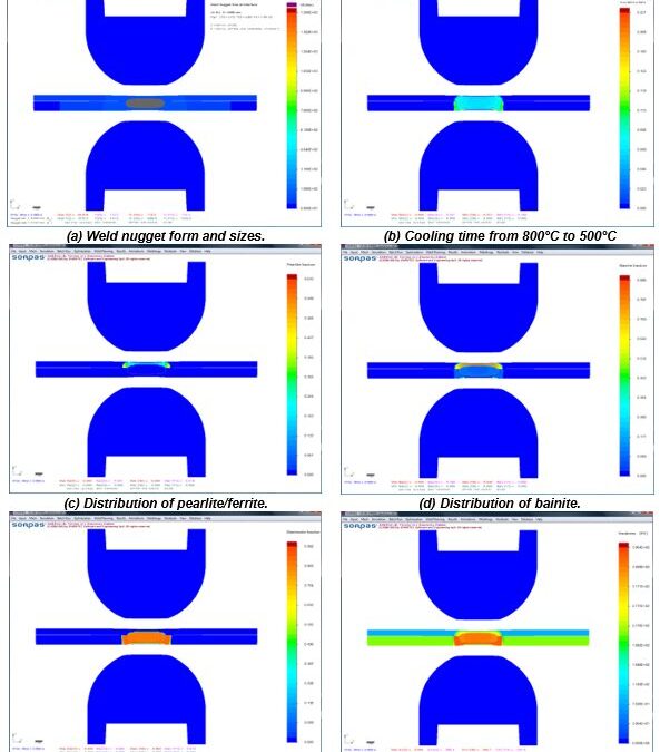
The advantages of numerical simulations for resistance welding are obvious for saving time and reducing costs in product developments and process optimizations. Today’s modeling techniques can predict temperature, microstructure, stress, and hardness distribution in the weld and Heat Affected Zone (HAZ) after welding. Commercial modeling software is available which considers material type, various current modes, machine characteristics, electrode geometry, etc. An example of process simulation results for spot welding of 0.8-mm DC 06 low-carbon steel to 1.2-mm DP 600 steel is shown in Figure 1. Obviously, this technique can apply to dissimilar thicknesses, material types, and geometries. Application of adhesives is also being used with these simulations. This simulation techniques are found to be very beneficial to predict vehicle crashworthiness as it can dramatically reduce the cost of crash evaluations.
You will find several articles in this section describing RSW modelling studies and procedures.
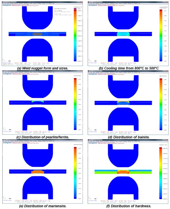
Figure 1: Simulation results with microstructures and hardness distribution for spot welding of 0.8-mm DC06 low-carbon steel to 1.2-mm DP 600 steel.Z-1
Manufacturing Issues
Spot Welding of Three Steel Sheets with Large Thickness Ratios
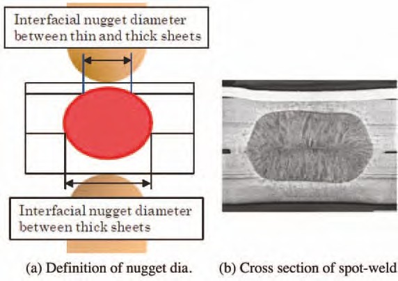
Car parts such as side panels are fabricated by spot welding three steel sheets together. When the outer steel sheet is a thin sheet of mild steel and the reinforcement steel sheets are thick sheets of HSS (that is, when there is a large thickness ratio between the sheets), it is often difficult to spot weld such sheets together. The term “thickness ratio” as used herein refers to the total thickness of the three steel sheets divided by the thickness of the thinnest steel sheet. Nuggets obtained by spot welding of three steel sheets are illustrated in Figure 1 (a). In the spot welding of three steel sheets with a large thickness ratio, it is difficult to form a nugget at the interface between thin and thick steel sheets, as shown in Figure 1 (b). The reason for this is that in spot welding, because of heat removal by the water-cooled electrode, the fusion progresses from the thickness center of the three steel sheets toward the outside, except for the heat generated by contact resistance at the steel sheet surfaces in the early stages of welding time. In addition, in view of the dimensional accuracy of actual members, it is necessary to set appropriate welding conditions when there is a gap between steel sheets. In practice, the proper welding current range is as shown in Figure 2. However, the welding current range is often narrower in one-step spot welding.
Figure 1: Three sheets spot welded.N-5
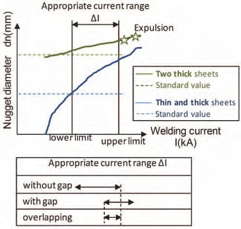
Figure 2: Weldability lobe of three sheets spot welded.
As a means of solving the above problem when there is no gap between the steel sheets, a method has been proposed in which the diameter of the electrode tip at the thin-sheet side is reduced and the welding force and current are varied during the welding time. In addition, a two- step pulsating current welding method (Figure 3) has been proposed in which neither the electrode diameter nor the welding force are changed. This method is described briefly below. Initially, during the first welding step, a relatively large welding current is passed to generate heat by using the contact resistance at the interface between the thin and thick steel sheets and that between the thick steel sheets. This method does not positively use the contact resistance that is effective when the electrode force is low. Since the method can be applied even under a high electrode force, it is particularly effective when there is a gap between the steel sheets to be welded together.
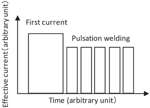
Figure 3: Welding current pattern.
An experiment was conducted by using the above technology. The materials used were a 0.6- mm-thick sheet of mild steel and two 1.6-mm-thick sheets of HSS (980 MPa class). Spacers 1.4-mm thick were inserted at intervals of 40 mm between the thin and thick steel sheets and between the thick steel sheets. A servomotor-driven, single-phase AC welder was used for the test. The electrode used was a Cr-Cu dome radius type with a 40-mm tip upper radius and 6-mm tip lower diameter. The welding force was 3.43 kN. To evaluate the diameter of fusion at the interface between the thin and thick sheets, which determines the proper current range, a chisel test was conducted at the interface and evaluated the plug diameter.
The test results are illustrated in Figure 4. The horizontal axis represents the first step welding current for one-step welding (welding time t1 = 18 cycles) and the second-step welding current for two-step welding (first welding time t1 = 18 cycles, second welding time t2 = 8 cycles) or pulsation welding [t1 = 18 cycles, t2 = (5-cycle heat/2-cycle cool) × 5]. For one- or two-step welding, the welding current range was less than 1 kA. Conversely, with pulsation, it was possible to secure a proper welding range of 3 kA or more (about 1.8 kA when there was no gap between the steel sheets).
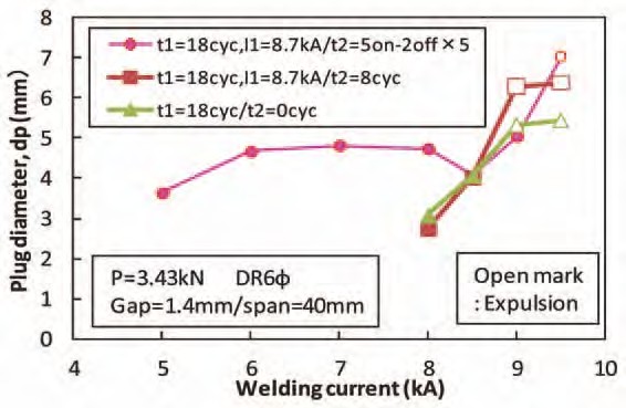
Figure 4: Current ranges for different welding current patterns.
In addition to the two-step pulsating current welding method (Figure 4 above), preheating the sheets at 20-25% of the normal current before beginning the impulses can be effective when joining three layers of extremely different thicknesses. Figure 5 shows a weld cross section using preheating prior to three impulses.
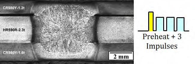
Figure 5: Cross section of three sheet spot weld including preheating prior to pulsations.C-6
Another solution to RSW three sheets is when the Fusion Zone (FZ) formation process is controlled by setting the welding current and welding force during welding in multiple steps; this is referred to as Intelligent Spot Welding. (ISW). Using this approach, nugget formation between a thin sheet and thick sheet becomes possible when reduced welding force is applied. In Step 1 of the welding process, a FZ is reliably formed between the thin sheet and thick sheet by applying conditions of low welding force, short welding time, and high current. In the subsequent Step 2, a FZ is formed between the two thick sheets by apply high welding force and a long welding time. The results are shown in Figure 6, in which welding is performed with the edge of three steel sheets positioned directly under the electrodes, and the behavior of FZ formation at the edge of the sheets was observed with a high-speed video camera. Condition (a) is welding under a constant welding force and condition (b) is ISW. In condition (a), a nugget was formed between the two thick sheets, but the nugget failed to grow to the thin sheet-thick sheet joint, and the two sheets were not welded. However, condition (b) shows that nuggets have formed between both the thin and thick sheet and between the two thick sheets. The optimal welding current range for Step 2 can be determined from nugget formation between the two thick sheets, resulting in a wide available current range equal to or greater than that in joint welding of two thick sheets.
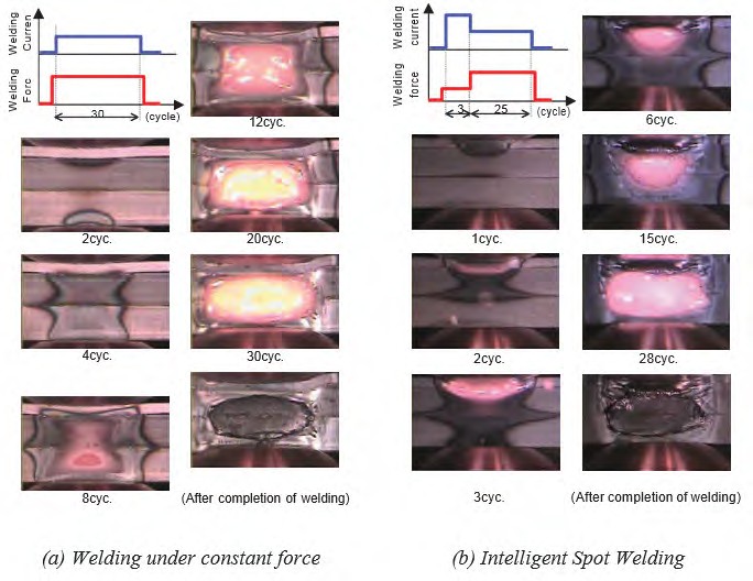
Figure 6: Results of observation of FZ formation phenomenon in RSW of three-sheet joint by high-speed video camera.J-1
Application of Spot Welding to Hollow Members
In spot welding of car bodies, the so-called direct spot welding (in which the welding current is passed while two or more steel sheets are pressed against each other) by the welding electrodes is used most commonly. However, for those parts with closed cross sections, it may become necessary to drill a working hole through which the electrodes for direct spot welding of the steel sheets can be passed. In this case, the decline in rigidity of the drilled part being compensated for by using a thicker steel sheet or providing a reinforcing member will inevitably increase the weight of the car body. Therefore, attempts were made to reduce the steel sheet thickness (weight) and secure the required stiffness simultaneously without drilling any hole in the steel sheets. Indirect spot welding was used, in which the steel sheets are pressed and welded by a couple of electrodes from one side at the same time. Because the steel sheets are pressed by electrodes from one side, the weld sinks and the area of contact between the steel sheets increases (the current density decreases) if an excessive force is applied, making it difficult to perform fusion welding. Conversely, if an excessively large current is applied, the local current density between the electrodes increases because of a shunt current, causing a crack or explosion.
Studies were made for various welding conditions for the combination of a hollow member with a 1.6-mm wall thickness and a sheet-formed member with a 0.7-mm thickness. By using an electrode with a specially designed tip and a DC power supply in combination, indirect spot welding could be performed of the above members without requiring any special pattern of conduction or pressing, even in the presence of a gap between the members or the presence of shunts (existing welding points). An example of the cross section of an indirect spot weld is illustrated in Figure 1, which clearly indicates that a sufficiently large nugget was formed.
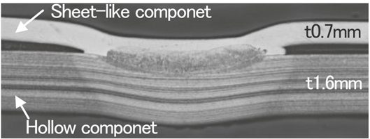
Figure 1: Cross section of indirect spot weld for hollow and sheet-like components.
For the indirect RSW with single-side access of the welding electrode, the variable controls of electrode force and current during welding were developed to promote the weld nugget formation. Experiments as well as numerical simulations were conducted to study the welding phenomena and optimize the welding process. It was verified that the nugget was stably formed with the developed process even when shunting was large. Figure 2 describes the effect of variable current and force on the promotion of weld nugget formation.
At the first stage with low welding current and high electrode force, the electric conduction with sufficient load at weld preheats the sheet, which promotes contacting area between the electrode and upper sheet and thus inhibits the expulsion from the surface. Meanwhile, contacting area between upper and lower sheets is also promoted forming the stable conduction path. Subsequently, at the second stage with high welding current and low electrode force, the nugget formation is effectively promoted with a heated region concentrated at the center in weld, avoiding the further penetration of welding electrode into the upper sheet and thus maintaining the current density.
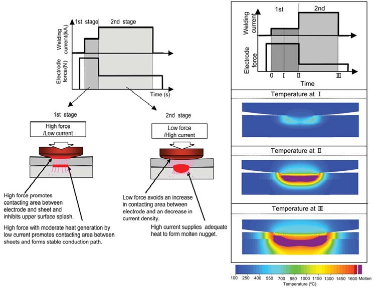
Figure 2: Concept of nugget formation process of variable current and force control for single-sided RSW.J-1
Back To Top
RSW Joint Performance Testing
It has been a long-standing challenge to extend the usage of the very high-strength steels in hydrogen-rich environments, given that these steels are prone to Hydrogen Cracking, due to their increased mechanical strength. Hydrogen embrittlement (HE) is known to be a premature fracture caused by a small amount of hydrogen atoms concentrated at highly stressed regions inside susceptible high tensile strength materials. (See examples in Figure 1.)
Figure 1: Examples of hydrogen embrittlement (HE) failure in RSW.
The factors controlling the occurrence of HE, susceptible microstructure, stress, and the presence of hydrogen, are well known and have been sufficiently quantified to develop procedures that minimize its occurrence mostly in arc welding thicker gauge steels. When advanced high strength steel (AHSS) with tensile strength over 980 MPa are applied in automotive applications, there is a small risk that hydrogen embrittlement fracture (sometime called delayed fracture) may occur after welding, while a vehicle is in use. Although there have been no reports that automotive parts made of AHSS have fractured due to hydrogen embrittlement, a risk assessment of delayed fracture for AHSS is considered necessary to ensure the safety of the automotive body and encourage wider use of Advanced High-Strength Steel (AHSS) sheets.
Another common embrittlement phenomenon involves the zinc coating discussed previously. Resistance spot welding is dependent on the interfacial contact resistance between the electrodes and the material. During welding, a metal with a lower melting point, such as zinc can penetrate in a liquid state into the grain boundaries of the material. By the end of the welding process, liquid metal embrittlement (LME) can become a problem due to the ductility of the grain boundary being reduced by the impeding tensile stress. (Example can be seen in Figure 2.) Also, brittle intermetallic compounds, such as Cu5Zn8, are created by the reaction with the Cu electrode and the material at the high temperature, which promotes LME or surface cracking.
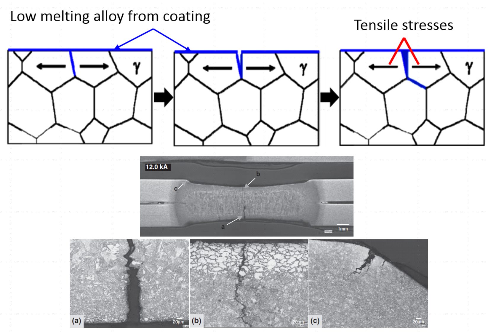
Figure 2: Description of (top image) and actual example (bottom) of the LME phenomenon in zinc coated AHSS.
There are many research papers investigating and analyzing Liquid Metal Embrittlement in mild steel and AHSS. LME is not unique to automotive AHSS steels or RSW, but is discovered in other ferrous materials, heat treatment and other welding processes. In spot welding AHSS, the complex microstructure and the greater spring back behavior of AHSS eventually lead to weld discontinuities such as LME.
A detailed multi-year, multi-organization study investigated the root causes of LME and how to test for, control, and prevent LME. The full report can be downloaded here, and is summarized in an AHSS Insights Blog.
The Joining Team of the Auto/Steel Partnership (A/SP) also recognizes the concerns surrounding LME, and conducted several rounds of testing, summarized here.
A/SP developed two separate procedures to test for Liquid Metal Embrittlement:
In summary, LME cracking may occur when a combination of tensile stress, liquid metal and susceptible microstructure exist. Studies are being performed to evaluate whether LME is mitigated by today’s automotive RSW processes, where the volume of welds significantly exceeds engineering requirements, or whether the occurrence of LME actually affects in-use properties at all.