Simulation
Predicting metal flow and failure is the essence of sheet metal forming simulation. Characterizing the stress-strain response to metal flow requires a detailed understanding of when the sheet metal first starts to permanently deform (known as the yield criteria), how the metal strengthens with deformation (the hardening law), and the failure criteria (for example, the forming limit curve). Complicating matters is that each of these responses changes as three-dimensional metal flow occurs, and are functions of temperature and forming speed.
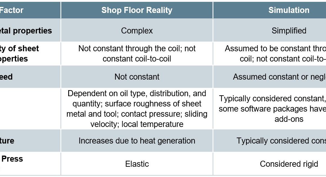
The ability to simulate these features reliably and accurately requires mathematical constitutive laws that are appropriate for the material and forming environments encountered. Advanced models typically improve prediction accuracy, at the cost of additional numerical computational time and the cost of experimental testing to determine the material constants. Minimizing these costs requires compromises, with some of these indicated in Table I created based on Citations B-16 and R-28.
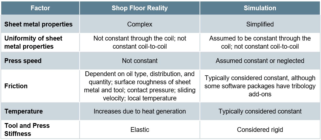
Table I: Deviations from reality made to reduce simulation costs. Based on Citations B-16 and R-28.
Yield Criteria
The yield criteria (also known as the yield surface or yield loci) defines the conditions representing the transition from elastic to plastic deformation. Assuming uniform metal properties in all directions allows for the use of isotropic yield functions like von Mises or Tresca. A more realistic approach considers anisotropic metal flow behavior, requiring the use of more complex yield functions like those associated with Hill, Barlat, Banabic, or Vegter.
No one yield function is best suited to characterize all metals. Some yield functions have many required inputs. For example, “Barlat 2004-18p” has 18 separate parameters leading to improved modeling accuracy – but only when inserting the correct values. Using generic textbook values is easier, but negates the value of the chosen model. However, determining these variables typically is costly and time-consuming, and requires the use of specialized test equipment.
Hardening Curve
Metals get stronger as they deform, which leads to the term work hardening. The flow stress at any given amount of plastic strain combines the yield strength and the strengthening from work hardening. In its simplest form, the stress-strain curve from a uniaxial tensile test shows the work hardening of the chosen sheet metal. This approach ignores many of the realities occurring during forming of engineered parts, including bi-directional deformation.
Among the simpler descriptions of flow stress are those from Hollomon, Swift, and Ludvik. More complex hardening laws are associated with Voce and Hockett-Sherby.
The strain path followed by the sheet metal influences the hardening. Approaches taken in the Yoshida-Uemori (YU) and the Homogeneous Anisotropic Hardening (HAH) models extend these hardening laws to account for Bauschinger Effect deformations (the bending-unbending associated with travel over beads, radii, and draw walls).
As with the yield criteria, accuracy improves when accounting for three-dimensional metal flow, temperature, and forming speed, and using experimentally determined input parameters for the metal in question rather than generic textbook values.
Failure Conditions
Defining the failure conditions is the other significant challenge in metal forming simulation. Conventional Forming Limit Curves describe necking failure under certain forming modes, and are easier to understand and apply than alternatives. Complexity and accuracy increase when accounting for non-linear strain paths using stress-based Forming Limit Curves. Necking failure is not the only type of failure mode encountered. Conventional FLCs cannot predict fracture on tight radii and cut edges, nor can they account for dimensional issues like springback. For these, failure criteria definitions which are more mathematically complex are appropriate.
Constitutive Laws and Their Influence
on Forming Simulation Accuracy
Many simulation packages allow for an easy selection of constitutive laws, typically through a drop-down menu listing all the built-in choices. This ease potentially translates into applying inappropriate selections unless the simulation analyst has a fundamental understanding of the options, the inputs, and the data generation procedures.
Some examples:
- The “Keeler Equation” for the estimation of FLC0 has many decades of evidence in being sufficiently accurate when applied to mild steels and conventional high strength steels. The simple inputs of n-value and thickness make this approach particularly attractive. However, there is ample evidence that using this approach with most advanced high strength steels cannot yield a satisfactory representation of the Forming Limit Curve.
- Even in cases where it is appropriate to use the Keeler Equation, a key input is the n-value or the strain hardening exponent. This value is calculated as the slope of the (natural logarithm of the true stress):(natural logarithm of the true strain curve). The strain range over which this calculation is made influences the generated n-value, which in turn impacts the calculated value for FLC0.
- The strain history as measured by the strain path at each location greatly influences the Forming Limit. However, this concept has not gained widespread understanding and use by simulation analysts.
- A common method to experimentally determine flow curves combines tensile testing results through uniform elongation with higher strain data obtained from biaxial bulge testing. Figure 1 shows a flow curve obtained in this manner for a bake hardenable steel with 220 MPa minimum yield strength. Shown in Figure 2 is a comparison of the stress-strain response from multiple hardening laws associated with this data, all generated from the same fitting strain range between yield and tensile strength. Data diverges after uniform elongation, leading to vastly different predictions. Note that the differences between models change depending on the metal grade and the input data, so it is not possible to say that one hardening law will always be more accurate than others.

Figure 1: Flow curves for a bake hardenable steel generated by combining tensile testing with bulge testing.L-20

Figure 2: The chosen hardening law leads to vastly different predictions of stress-strain responses.L-20
- Analysts often treat Poisson’s Ratio and the Elastic Modulus as constants. It is well known that the Bauschinger Effect leads to changes in the Elastic Modulus, and therefore impacts springback. However, there are also significant effects in both Poisson’s Ratio (Figure 3) and the Elastic Modulus (Figure 4) as a function of orientation relative to the rolling direction. Complicating matters is that this effect changes based on the selected metal grade.

Figure 3: Poisson’s Ratio as a Function of Orientation for Several Grades (Drawing Steel, DP 590, DP 980, DP 1180, and MS 1700) D-11

Figure 4: Modulus of Elasticity as a Function of Orientation for Several Grades (Drawing Steel, DP 590, DP 980, DP 1180, and MS 1700) D-11
Complete material card development requires results from many tests, each attempting to replicate one or more aspects of metal flow and failure. Certain models require data from only some of these tests, and no one model typically is best for all metals and forming conditions. Tests described below include:
- Tensile testing [room temperature at slow strain rates to elevated temperature with accelerated strain rates]
- Biaxial bulge testing
- Biaxial tensile testing
- Shear testing
- V-bending testing
- Tension-compression testing with cyclic loading
- Friction
Tensile testing is the easiest and most widely available mechanical property evaluation required to generate useful data for metal forming simulation. However, a tensile test provides a complete characterization of material flow only when the engineered part looks like a dogbone and all deformation resulted from pulling the sample in tension from the ends. That is obviously not realistic. Getting tensile test results in more than just the rolling direction helps, but generating those still involves pulling the sample in tension. Three-dimensional metal flow occurs, and the stress-strain response of the sheet metal changes accordingly.
The uniaxial tensile test generates a draw deformation strain state since the edges are free to contract. A plane strain tensile test requires using a modified sample geometry with an increased width and decreased gauge length,
Forming all steels involves a thermal component, either resulting from friction and deformation during “room temperature” forming or the intentional addition of heat such as used in press hardening. In either case, modeling the response to temperature requires data from tests occurring at the temperature of interest, at appropriate forming speeds. Thermo-mechanical simulators like Gleeble™ generate such data.
Conventional tensile testing occurs at deformation rates of 0.001/sec. Most production stamping occurs at 10,000x that amount, or 10/sec. Crash events can be 2 orders of magnitude faster, at about 1000/sec. The stress-strain response varies by both testing speed and grade. Therefore, accurate simulation models require data from higher-speed tensile testing. Typically, generating high speed tensile data involves drop towers or Split Hopkinson Pressure Bars.
A pure uniaxial stress state exists in a tensile test only until reaching uniform elongation and the beginning of necking. Extrapolating uniaxial tensile data beyond uniform elongation risks introducing inaccuracies in metal flow simulations. Biaxial bulge testing generates the data for yield curve extrapolation beyond uniform elongation. This stretch-forming process deforms the sheet sample into a dome shape using hydraulic pressure, typically exerted by water-based fluids. Citation I-12 describes a standard test procedure for biaxial bulge testing.
A Marciniak test used to create Forming Limit Curves generates in-plane biaxial strains. Whereas FLC generation uses 100 mm diameter samples, larger samples allow for extraction of full-size tensile bars. Although this approach generates samples containing biaxial strains, the extracted samples are tested uniaxially in the conventional manner.
Biaxial tensile testing allows for the determination of the yield locus and the biaxial anisotropy coefficient, which describes the slope of the yield surface at the equi-biaxial stress state. This test uses cruciform-shaped test pieces with parallel slits cut into each arm. Citation I-13 describes a standard test procedure for biaxial tensile testing. The biaxial anisotropy coefficient can also be determined using the disk compression testing as described in Citation T-21.
Shear testing characterizes the sheet metal in a shear loading condition. There is no consensus on the specimen type or testing method. However, the chosen testing set-up should avoid necking, buckling, and any influence of friction.
V-bending tests determine the strain to fracture under specific loading conditions. Achieving plane strain or plane stress loading requires use of a test sample with features promoting the targeted strain state.
Tension-compression testing characterizes the Bauschinger Effect. Multiple cycles of tension-compression loading captures cyclic hardening behavior and elastic modulus decay, both of which improve the accuracy of springback predictions. Again, no standard procedure exists. The biggest challenge with this test is preventing buckling from occurring during in-plane compressive loading. Related to this is the need to compensate for the friction caused by the anti-buckling mechanism in the stress-strain curves .
Friction is obviously a key factor in how metal flows. However, there is no one simple value of friction that applies to all surfaces, lubricants, and tooling profiles. The coefficient of friction not only varies from point to point on each stamping but changes during the forming process. Determining the coefficient of friction experimentally is a function of the testing approach used. The method by which analysts incorporate friction into simulations influences the accuracy and applicability of the results of the generated model.
Studies are underway to reduce the costs and challenges of obtaining much of this data. It may be possible, for example, to use Digital Image Correlation (DIC) during a simple uniaxial tensile testing to quantify r-value at high strains, determine the material hardening behavior along with strain rate sensitivity, assess the degradation of Young’s Modulus during unloading, and use the detection of the onset of local neck to help account for non-linear strain path effects.S-110
Application of Advanced Testing to Failure Predictions
Global formability failures occur when the forming strains exceed the necking forming limit throughout the entire thickness of the sheet. Advanced steels are at risk of local formability failures where the forming strains exceed the fracture forming limit at any portion of the thickness of the sheet.
Fracture forming limit curves plot higher than the conventional necking forming limit curves on a graph showing major strain on the vertical axis and minor strain on the horizontal axis. In conventional steels the gap between the fracture FLC and necking FLC is relatively large, so the part failure is almost always necking. The forming strains are not high enough to reach the fracture FLC.
In contrast, AHSS grades are characterized by a smaller gap between the necking FLC and the fracture FLC. Depending on the forming history, part geometry (tight radii), and blank processing (cut edge quality), forming strains may exceed the fracture FLC at an edge or bend before exceeding the necking FLC through-thickness. In this scenario, the part will fracture without signs of localized necking.
A multi-year study funded by the American Iron and Steel Institute at the University of Waterloo Forming and Crash Lab describes a methodology used for forming and fracture characterization of advanced high strength steels, the details of which can be found in Citations B-11, W-20, B-12, B-13, R-5, N-13 and G-19.
This collection of studies, as well as work coming out of these studies, show that relatively few tests sufficiently characterize forming and fracture of AHSS grades. These studies considered two 3rd Gen Steels, one with 980MPa tensile strength and one with 1180MPa tensile.
- The yield surface as generated with the Barlat YLD2000-2d yield surface (Figure 5) comes from:
- Conventional tensile testing at 0, 22.5, 45, 67.5, and 90 degrees to the rolling direction, determining the yield strength and the r-value;
- Disc compression tests according to the procedure in Citation T-21 to determine the biaxial R-value, rb.

Figure 5: Tensile testing and disc compression testing generate the Barlat YLD2000-2d yield surface in two 3rd Generation AHSS Grades B-13
- Creating the hardening curve uses a procedure detailed in Citations R-5 and N-13, and involves only conventional tensile and shear testing using the procedure included in Citation P-15.

Figure 6: Test geometries for hardening curve generation. Left image: Tensile; Right image: Shear.N-13
- Characterizing formability involved generating a Forming Limit Curve using Marciniak data or process-corrected Nakazima data. (See our article on non-linear strain paths) and Citation N-13 for explanation of process corrections]. Either approach resulted in acceptable characterizations.
- Fracture characterization uses four plane stress tests: shear, conical hole expansion, V-bending, and a biaxial dome test. The result from these tests calibrate the fracture locus describing the stress states at fracture.
Back To Top

1stGen AHSS, AHSS, Steel Grades
Dual Phase (DP) steels have a microstructure consisting of a ferritic matrix with martensitic islands as a hard second phase, shown schematically in Figure 1. The soft ferrite phase is generally continuous, giving these steels excellent ductility. When these steels deform, strain is concentrated in the lower-strength ferrite phase surrounding the islands of martensite, creating the unique high initial work-hardening rate (n-value) exhibited by these steels. Figure 2 is a micrograph showing the ferrite and martensite constituents.

Figure 1: Schematic of a Dual Phase steel microstructure showing islands of martensite in a matrix of ferrite.

Figure 2: Micrograph of Dual Phase Steel
Hot rolled DP steels do not have the benefit of an annealing cycle, so the dual phase microstructure must be achieved by controlled cooling from the austenite phase after exiting the hot strip mill finishing stands and before coiling. This typically requires a more highly alloyed chemistry than cold rolled DP steels require. Higher alloying is generally associated with a change in welding practices.
Continuously annealed cold-rolled and hot-dip coated Dual Phase steels are produced by controlled cooling from the two-phase ferrite plus austenite (α + γ) region to transform some austenite to ferrite before a rapid cooling transforms the remaining austenite to martensite. Due to the production process, small amounts of other phases (bainite and retained austenite) may be present.
Higher strength dual phase steels are typically achieved by increasing the martensite volume fraction. Depending on the composition and process route, steels requiring enhanced capability to resist cracking on a stretched edge (as typically measured by hole expansion capacity) can have a microstructure containing significant quantities of bainite.
The work hardening rate plus excellent elongation creates DP steels with much higher ultimate tensile strengths than conventional steels of similar yield strength. Figure 3 compares the engineering stress-strain curve for HSLA steel to a DP steel curve of similar yield strength. The DP steel exhibits higher initial work hardening rate, higher ultimate tensile strength, and lower YS/TS ratio than the HSLA with comparable yield strength. Additional engineering and true stress-strain curves for DP steel grades are presented in Figures 4 and 5.
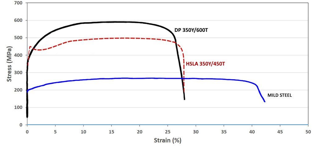
Figure 3: A comparison of stress strain curves for mild steel, HSLA 350/450, and DP 350/600K-1

Figure 4: Engineering stress-strain curves for a series of DP steel grades.S-5, V-1 Sheet thicknesses: DP 250/450 and DP 500/800 = 1.0mm. All other steels were 1.8-2.0mm.

Figure 5: True stress-strain curves for a series of DP steel grades.S-5, V-1 Sheet thicknesses: DP 250/450 and DP 500/800 = 1.0mm. All other steels were 1.8-2.0mm.
DP and other AHSS also have a bake hardening effect that is an important benefit compared to conventional higher strength steels. The extent of the bake hardening effect in AHSS depends on an adequate amount of forming strain for the specific chemistry and thermal history of the steel.
In DP steels, carbon enables the formation of martensite at practical cooling rates by increasing the hardenability of the steel. Manganese, chromium, molybdenum, vanadium, and nickel, added individually or in combination, also help increase hardenability. Carbon also strengthens the martensite as a ferrite solute strengthener, as do silicon and phosphorus. These additions are carefully balanced, not only to produce unique mechanical properties, but also to maintain the generally good resistance spot welding capability. However, when welding the higher strength grades (DP 700/1000 and above) to themselves, the spot weldability may require adjustments to the welding practice.
Examples of current production grades of DP steels and typical automotive applications include:
| DP 300/500 |
Roof outer, door outer, body side outer, package tray, floor panel |
| DP 350/600 |
Floor panel, hood outer, body side outer, cowl, fender, floor reinforcements |
| DP 500/800 |
Body side inner, quarter panel inner, rear rails, rear shock reinforcements |
| DP 600/980 |
Safety cage components (B-pillar, floor panel tunnel, engine cradle, front sub-frame package tray, shotgun, seat) |
| DP 700/1000 |
Roof rails |
| DP 800/1180 |
B-Pillar upper |
Some of the specifications describing uncoated cold rolled 1st Generation dual phase (DP) steel are included below, with the grades typically listed in order of increasing minimum tensile strength and ductility. Different specifications may exist which describe hot or cold rolled, uncoated or coated, or steels of different strengths. Many automakers have proprietary specifications which encompass their requirements.
- ASTM A1088, with the terms Dual phase (DP) steel Grades 440T/250Y, 490T/290Y, 590T/340Y, 780T/420Y, and 980T/550YA-22
- EN 10338, with the terms HCT450X, HCT490X, HCT590X, HCT780X, HCT980X, HCT980XG, and HCT1180XD-6
- JIS G3135, with the terms SPFC490Y, SPFC540Y, SPFC590Y, SPFC780Y and SPFC980YJ-3
- JFS A2001, with the terms JSC590Y, JSC780Y, JSC980Y, JSC980YL, JSC980YH, JSC1180Y, JSC1180YL, and JSC1180YHJ-23
- VDA 239-100, with the terms CR290Y490T-DP, CR330Y590T-DP, CR440Y780T-DP, CR590Y980T-DP, and CR700Y980T-DPV-3
- SAE J2745, with terms Dual Phase (DP) 440T/250Y, 490T/290Y, 590T/340Y, 6907/550Y, 780T/420Y, and 980T/550YS-18
1stGen AHSS, 3rdGen AHSS, AHSS, Steel Grades
topofpage
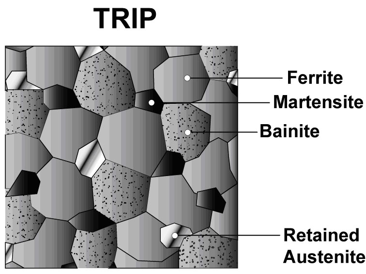
The microstructure of Transformation Induced Plasticity (TRIP) steels contains a matrix of ferrite, with retained austenite, martensite, and bainite present in varying amounts. Production of TRIP steels typically requires the use of an isothermal hold at an intermediate temperature, which produces some bainite. Higher silicon and carbon content of TRIP steels result in significant volume fractions of retained austenite in the final microstructure. Figure 1 shows a schematic of TRIP steel microstructure, with Figure 2 showing a micrograph of an actual sample of TRIP steel. Figure 3 compares the engineering stress-strain curve for HSLA steel to a TRIP steel curve of similar yield strength.

Figure 1: Schematic of a TRIP steel microstructure showing a matrix of ferrite, with martensite, bainite and retained austenite as the additional phases.
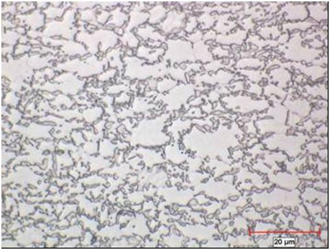
Figure 2: Micrograph of Transformation Induced Plasticity steel.
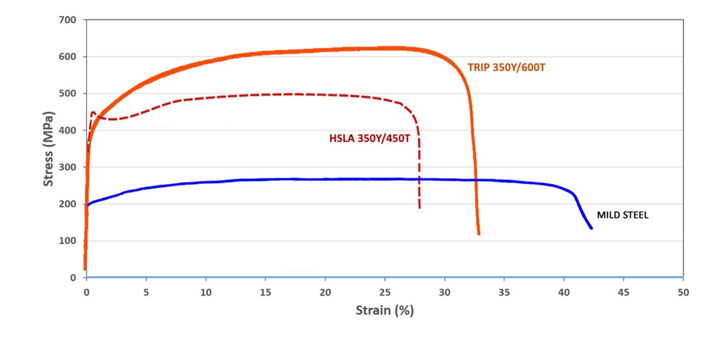
Figure 3: A comparison of stress strain curves for mild steel, HSLA 350/450, and TRIP 350/600.K-1
During deformation, the dispersion of hard second phases in soft ferrite creates a high work hardening rate, as observed in the DP steels. However, in TRIP steels the retained austenite also progressively transforms to martensite with increasing strain, thereby increasing the work hardening rate at higher strain levels. This is known as the TRIP Effect. This is illustrated in Figure 4, which compares the engineering stress-strain behavior of HSLA, DP and TRIP steels of nominally the same yield strength. The TRIP steel has a lower initial work hardening rate than the DP steel, but the hardening rate persists at higher strains where work hardening of the DP begins to diminish. Additional engineering and true stress-strain curves for TRIP steel grades are shown in Figure 5.
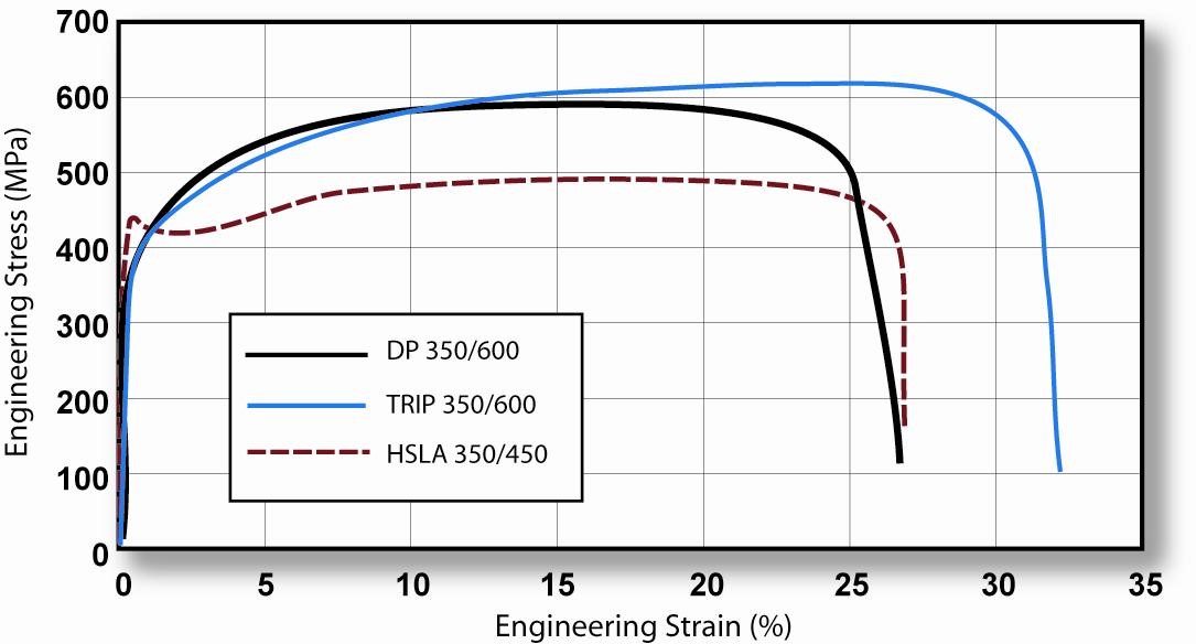
Figure 4: TRIP 350/600 with a greater total elongation than DP 350/600 and HSLA 350/450. K-1
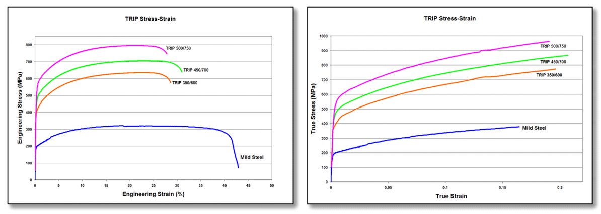
Figure 5: Engineering stress-strain (left graphic) and true stress-strain (right graphic) curves for a series of TRIP steel grades. Sheet thickness: TRIP 350/600 = 1.2mm, TRIP 450/700 = 1.5mm, TRIP 500/750 = 2.0mm, and Mild Steel = approx. 1.9mm. V-1
The strain hardening response of TRIP steels are substantially higher than for conventional HSS, resulting in significantly improved formability in stretch deformation. This response is indicated by a comparison of the n-value for the grades. The improvement in stretch formability is particularly useful when designers take advantage of the improved strain hardening response to design a part utilizing the as-formed mechanical properties. High n-value persists to higher strains in TRIP steels, providing a slight advantage over DP in the most severe stretch forming applications.
Austenite is a higher temperature phase and is not stable at room temperature under equilibrium conditions. Along with a specific thermal cycle, carbon content greater than that used in DP steels are needed in TRIP steels to promote room-temperature stabilization of austenite. Retained austenite is the term given to the austenitic phase that is stable at room temperature.
Higher contents of silicon and/or aluminum accelerate the ferrite/bainite formation. These elements assist in maintaining the necessary carbon content within the retained austenite. Suppressing the carbide precipitation during bainitic transformation appears to be crucial for TRIP steels. Silicon and aluminum are used to avoid carbide precipitation in the bainite region.
The carbon level of the TRIP alloy alters the strain level at which the TRIP Effect occurs. The strain level at which retained austenite begins to transform to martensite is controlled by adjusting the carbon content. At lower carbon levels, retained austenite begins to transform almost immediately upon deformation, increasing the work hardening rate and formability during the stamping process. At higher carbon contents, retained austenite is more stable and begins to transform only at strain levels beyond those produced during forming. At these carbon levels, retained austenite transforms to martensite during subsequent deformation, such as a crash event.
TRIP steels therefore can be engineered to provide excellent formability for manufacturing complex AHSS parts or to exhibit high strain hardening during crash deformation resulting in excellent crash energy absorption.
The additional alloying requirements of TRIP steels degrade their resistance spot-welding behavior. This can be addressed through weld cycle modification, such as the use of pulsating welding or dilution welding. Table 1 provides a list of current production grades of TRIP steels and example automotive applications:

Table 1: Current Production Grades Of TRIP Steels And Example Automotive Applications.
Some of the specifications describing uncoated cold rolled 1st Generation transformation induced plasticity (TRIP) steel are included below, with the grades typically listed in order of increasing minimum tensile strength and ductility. Different specifications may exist which describe hot or cold rolled, uncoated or coated, or steels of different strengths. Many automakers have proprietary specifications which encompass their requirements.
• ASTM A1088, with the terms Transformation induced plasticity (TRIP) steel Grades 690T/410Y and 780T/440YA-22
• JFS A2001, with the terms JSC590T and JSC780TJ-23
• EN 10338, with the terms HCT690T and HCT780TD-18
• VDA 239-100, with the terms CR400Y690T-TR and CR450Y780T-TRV-3
• SAE J2745, with terms Transformation Induced Plasticity (TRIP) 590T/380Y, 690T/400Y, and 780T/420YS-18
Transformation Induced Plasticity Effect
Austenite is not stable at room temperature under equilibrium conditions. An austenitic microstructure is retained at room temperature with the combined use of a specific chemistry and controlled thermal cycle. Deformation from sheet forming provides the necessary energy to allow the crystallographic structure to change from austenite to martensite. There is insufficient time and temperature for substantial diffusion of carbon to occur from carbon-rich austenite, which results in a high-carbon (high strength) martensite after transformation. Transformation to high strength martensite continues as deformation increases, as long as retained austenite is still available to be transformed.
Alloys capable of the TRIP effect are characterized by a high ductility – high strength combination. Such alloys include 1st Gen AHSS TRIP steels, as well as several 3rd Gen AHSS grades like TRIP-Assisted Bainitic Ferrite, Carbide Free Bainite, and Quench & Partition Steels.
Back to the Top
![Bake Hardenable]()
AHSS, Conventional HSS, Steel Grades
BH Grades
Bake Hardenable (BH) steels grades are conventional High Strength Steels that exhibit a Bake Hardening Effect. BH steels exhibit an increase in yield strength after room-temperature stamping followed by processing through a thermal cycle comparable to the time-temperature profile used in paint curing (or baking) – approximately 170 °C for 20 minutes. Bake hardenability is characterized by determining the Bake Hardening Index.
Bake Hardenable steel grades have yield strength at shipment from the steel mills of 180 MPa to 300 MPa (approximately 25 ksi to 45 ksi). The grades at the lower strength levels are capable of being produced with a Class A surface finish and are used in applications where dent resistance is desired in thin sheet steel. Applications for the higher strength BH steels include structural parts where Class A surface is not required. The higher strength after forming and baking is the reason automakers might use these in body structure applications, potentially contributing to vehicle lightweighting efforts.
These grades work harden approximately 30 MPa when 2% strain is introduced, either from stamping or during a tensile test, which is similar to dent resistant IF-HS. In contrast to IF-HS, the paint-bake cycle after forming results in an additional yield strength increase. The minimum strength increase from baking is specified by some automakers as 20 MPa to 35 MPa, measured after applying a defined level of strain.
Higher yield strength directly improves the dent performance. Even though BH grades and their non bake hardening counterpart IF-HS grades may have similar yield strength and thickness after forming, bake hardenable steels will show superior dent resistance due to the increase in yield strength from the paint baking operation.
Ferrite is the main microstructural phase of BH steels. The strengthening from the paint bake cycle is due to the controlled amount of carbon remaining in solid solution (on the order of 25 ppm) when the steel leaves the production mill. At the baking temperatures after the part is formed, the dissolved carbon migrates to pin any free dislocations created from stamping. This increases the yield strength of the formed part for increased dent resistance. Formability does not suffer, since the strength increase occurs after stamping.
Most Advanced High Strength Steel (AHSS) grades also exhibit a Bake Hardening Effect, achieving yield strength increases of 40 MPa to 120 MPa from an appropriate thermal cycle. AHSS grades are not categorized with traditional bake hardenable steels, since their primary characteristics and applications are typically, but not exclusively, different. One exception are some Dual Phase (DP) steels available with a Class A surface, which are used as skin panels to combine excellent dent resistance with lightweighting benefits.
Some of the specifications describing uncoated Bake Hardenable (BH) steel are included below, with the grades typically listed in order of increasing minimum yield strength and ductility. Different specifications may exist which describe uncoated or coated, or steels of different strengths.
- ASTM A1008M, with the terms BHS 26 [180], BHS 31 [210], BHS 35 [240], BHS 41 [280], BHS 44 [300]A-25
- EN10268, with the terms HC180B, HC220B, HC260B, and HC300LAD-3
- JIS G3135, with the term SPFC340HJ-3
- JFS A2001, with the terms JSC270H, JSC340HJ-23
- VDA239-100, with the terms CR180BH, CR210BH, CR240BH, and CR270BHV-3
Bake Hardening Effect
Bake Hardenable Steel Grades and most AHSS grades exhibit a Bake Hardening Effect, meaning that there is an increase in yield strength after room-temperature stamping followed by processing through a thermal cycle comparable to the time-temperature profile used in paint curing (or baking) – approximately 170 °C for 20 minutes.
The degree to which a sample is bake hardenable is characterized by the Bake Hardening Index.
In Bake Hardenable Steel Grades, solid solution hardening elements like phosphorus, manganese, and silicon are used to achieve the desired initial strength. For AHSS, the initial strength is determined by the balance and volume fraction of microstructural components like ferrite, bainite, retained austenite, and martensite. In both cases, a specifically engineered amount of dissolved carbon in the ferritic matrix causes an additional increase in the yield strength through controlled carbon aging during the paint-bake thermal cycle. The bake hardening process in AHSS grades is more complex, and results in substantially higher values of the Bake Hardening Index.
Figure 1 shows the work hardening and bake hardening increases for samples of three High-Strength steel grades having the same as-received yield strength prior to 2% pre-straining and baking. The HSLA steel shows little or no bake hardening, while AHSS such as DP and Transformation Induced Plasticity (TRIP) steels show a large positive bake hardening index. The DP steel also has significantly higher work hardening than HSLA or TRIP steel because of higher strain hardening at low strains. No aging behavior of AHSS has been observed due to storage of as-received coils or blanks over a significant length of time at normal room temperatures. Hence, significant mechanical property changes of shipped AHSS products during normal storage conditions are unlikely.
The higher bake hardening index (BHI) of AHSS grades DP 600 and TRIP 700 is also shown in Figure 2. While BHI is determined at a prestrain of 2%, this graph indicates that even higher levels of bake hardenability can be achieved with increasing strain. In a stamping where most areas have more than 2% strain, combining this higher bake hardenability with the increased work hardening that occurs with increasing strain results in a formed panel having a strength markedly higher than the incoming flat steel. This is beneficial for crash energy management.

Figure 1: Comparison of work hardening (WH) and bake hardening (BH) for TRIP, DP, and HSLA steels given a 2% prestrain. S-1, K-3

Figure 2: Bake hardening responses of several HSS and AHSS products with varying pre-strain, reproduced from Figure 3 in Citation B-6. The bracketed numbers after each grade are references within the cited paper.
Bake Hardenability of Exposed Quality Dual Phase Steels
Dent resistance is a function of the yield strength in the formed panel after it completes the paint baking cycle. Based on this premise, grades with higher bake hardenability, such as AHSS, should have substantially higher dent resistance. Application of AHSS grades to capitalize on improved dent resistance also requires their production at the desired thickness and width along with surface characteristics appropriate for Class A exposed quality panels. Some DP steels meet these tight requirements specified by the automotive industry.
A recent studyK-49 highlights this improved dent resistance. This work presents the experimental results and associated numerical investigation of the dent testing of DP270Y490T, a DP steel grade with 490 MPa minimum tensile strength. Tests performed to the SAE J2575 procedureS-7 measure the resultant dent depth after testing, so therefore smaller depths indicate improved performance. Compared with samples not processed through a bake hardening cycle, dent depth reductions occur with hotter and longer cycles, as shown in Figure 3. Increasing temperature plays a more significant role in dent depth reduction than increasing time. This work also reinforces that bake hardenability must be incorporated into simulation models in order to improve the accuracy of dent resistance predictions.
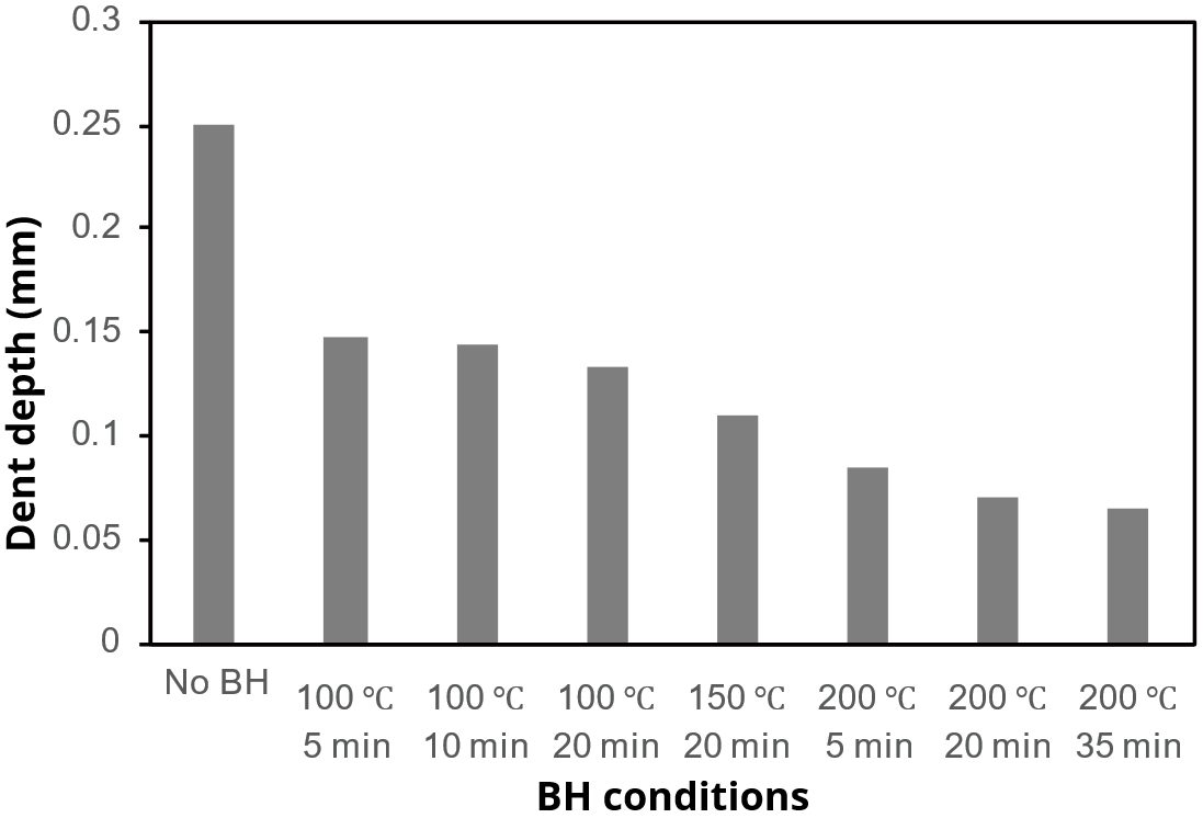
Figure 3: Dent resistance of DP270Y490T according to SAE J2575S-7 as a function of baking test conditions.K-49 Lower dent depth indicates better dent resistance.
Measuring The Bake Hardenability Index
Bake hardenability is characterized by determining the Bake Hardening Index, or BHI.
The Bake Hardening Index (BH2) is determined by taking a conventional tensile test sample and pulling it to 2% strain. This is known as a 2% pre-strain. The sample is then put into an oven for a thermal cycle designed to be typical of an automotive paint curing (paint baking) cycle: 170 °C for 20 minutes. The temperature and time may be different depending on the end-user specifications.
Some companies may specify BH0, which uses the same thermal cycle without the 2% pre-strain. BH5 or BH10 (5% or 10% pre-strain, respectively) may also be reported.
The experimental procedure and calculation of BH2 is standardized in EN 10325D-4 and JIS G 3135J-3, and is similarly described in several other specifications.
Figure 4 defines the measurement for work hardening (B minus A), unloading to C for baking, and reloading to yielding at D for measurement of bake hardening (D minus B). Note that the bake hardening index shown here is measured up to the lower yield point, which is consistent with the EN 10325 definition. JIS G 3135 prescribes the use of the upper yield point.

Figure 4: Measurement of work hardening index and bake hardening index. BHI is measured using the lower yield point in EN 10325D-4 and with the upper yield point in JIS G 3135J-3.
Back To Top
![Bake Hardenable]()
Mechanical Properties
Engineering stress-strain units are based on the starting dimensions of the tensile test sample: Engineering stress is the load divided by the starting cross-sectional area, and engineering strain is the change in length relative to the starting gauge length (2 inches, 50mm, or 80mm for ASTM [ISO I], JIS [ISO III], or DIN [ISO II] tensile test samples, respectively.)
Metals get stronger with deformation through a process known as strain hardening or work hardening. This is represented on the stress strain curve by the parabolic shaped section after yielding.
Concurrent with the strengthening as the tensile test sample elongates is the reduction in the width and thickness of the test sample. This reduction is necessary to maintain consistency of volume of the test sample.
Initially the positive influence of the strengthening from work hardening is greater than the negative influence of the reduced cross-section, so the stress-strain curve has a positive slope. As the influence of the cross-section reduction begins to overpower the strengthening increase, the stress-strain curve slope approaches zero.
When the slope is zero, the maximum is reached on the vertical axis of strength. This point is known as the ultimate tensile strength, or simply the tensile strength. The strain at which this occurs is known as uniform elongation.
Strain concentration after uniform elongation results in the formation of diffuse necks and local necks and ultimately fracture.

Figure 1: Tensile Strength is the Strength at the Apex of the Engineering Stress – Engineering Strain Curve.


