Steel, and specifically advanced high strength steel, satisfies automotive industry requirements for safety, emissions, fuel efficiency, manufacturability, durability, and affordability.
Affordability
The automotive industry has adopted light-weighting as a key part of their greenhouse gas reduction strategy. This strategy, however, must be executed in an affordable manner.
Key reasons to deploy advanced high strength steels in automotive body structures include better performance in crash energy management and increased strength allowing this performance to be achieved with thinner materials, translating into lower vehicle weight. Thinner gauges mean a reduced amount of purchased material is needed to achieve this enhanced performance.
Today’s steels enable significant mass reduction, while meeting crash and other functional requirements, while preserving affordability. WorldAutoSteel vehicle programs and competitive benchmarking studies (here, here and here) have clearly demonstrated that optimized steel body structures can be constructed with little to no increases in total system cost relative to conventional body structures.
Recognizing these benefits, global automakers continue to base their fleet on steel-intensive body structures and rely on advanced high strength steel to help them meet customer expectations and government regulations in the most cost-effective way possible.
Most steel companies are extending their research and development efforts to expand the range of properties available through these new steels, to enable the production of safe and environmentally friendly vehicles.
Safety
The percentage of high strength steels used in light vehicles relative to other materials continues to grow, and much of the growth has been fueled by increasingly stringent safety regulations and ratings systems. Consumers are demanding safe cars, and governments are responding with new tests and standards that influence auto body structures, design and materials. The results of vehicle safety performance tests are therefore a strong incentive affecting consumer purchasing decisions.
In the United States, the National Highway Traffic Safety Administration (NHTSA) sets standards for vehicle safety, such as those for impact resistance, restraints, and fuel economy.N-26 Testing by the U.S. Insurance Institute for Highway Safety (IIHS) has encouraged improved frontal, side, and rear impact ratings, as well as roof strength and rollover ratings, for vehicles on the road today.I-5 Numerous New Car Assessment Programs around the world measures vehicle performance in a variety of crash tests, including front, side and pole impacts, and impacts with pedestrians with the goal of informing the public about the relative safety performance amongst vehicles. A limited number of these are shown in Citations G-5, E-13, and J-25. Citations C-35 and C-36 summarize the testing that goes into these global New Car Assessment Program standards. Meeting these standards and improving performance often requires the addition of weight to the vehicle.
Diligent application of advanced steels leads to safe, lighter-weight body structures. Tailoring the engineering design and forming approaches to the material characteristics and properties allows for optimized use of these newer grades and avoids excess or redundant mass in the structure. The FSV program showed that natural, non-linear load paths allow for more effective crash management and lighter-weight structures, attainable through design optimization and rigorous application of AHSS.
Deploying Advanced Steels in Automotive Body Structures
Several key considerations drive material selection for automotive applications, including safety, fuel efficiency, environmental performance, manufacturability, durability, and quality. For exposed parts, aesthetic concerns related to paint finish and dent resistance are also important. These factors manifest themselves differently in each component of the vehicle, and materials are selected to match each set of performance requirements in the most efficient means possible.
Crash Performance
Perhaps the most critical design considerations for a vehicle structure relate to its ability to carry the required static and dynamic loads, particularly during a crash. Both materials strategy and geometric design play important roles in determining the final load paths and part details.
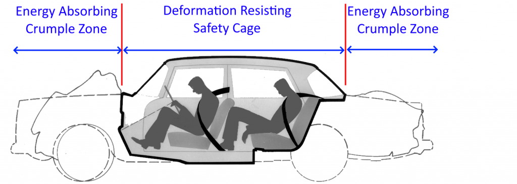
Two generalized areas of the car have very different safety requirements, as shown in Figure 1. The passenger compartment, enclosed in a rigid “safety cage,” is designed to protect the passengers in the event of a low or high-speed crash; the structure should prevent any deformation or intrusions that would compromise the integrity of the cage structure and impinge on the space around the passengers.
“Crumple zones,” located at the front and rear of the vehicle, are designed to absorb as much energy as possible in the event of a front or rear collision. By absorbing the energy over a distance, the crumple zone will cushion the impact and help preserve the structural integrity of the passenger compartment.
Table 1 presents general guidelines for materials selection in the crumple zone and the passenger compartment.
Figure 1: The major crash management zones of a vehicle.
Table 1: Steel Grade Strategies For Targeted Safety Performance
|
Crash Zone |
Performance Requirements During Crash |
Material properties to meet need |
Evidence of Performance |
Potential Steel Selection |
| Energy Absorbing Crumple Zone |
High energy absorption over a distance |
High work hardening, strength, and ductility |
Large area under the stress-strain curve |
Dual Phase,
Complex Phase,
Transformation-Induced Plasticity,
3rd Generation Steels |
| Deformation Resisting Safety Cage |
No deformation or intrusion |
High yield strength |
Highest tensile strength |
Martensite,
Press Hardening
Hot Formed,
>980 MPa Dual Phase,
>980 MPa Complex Phase |
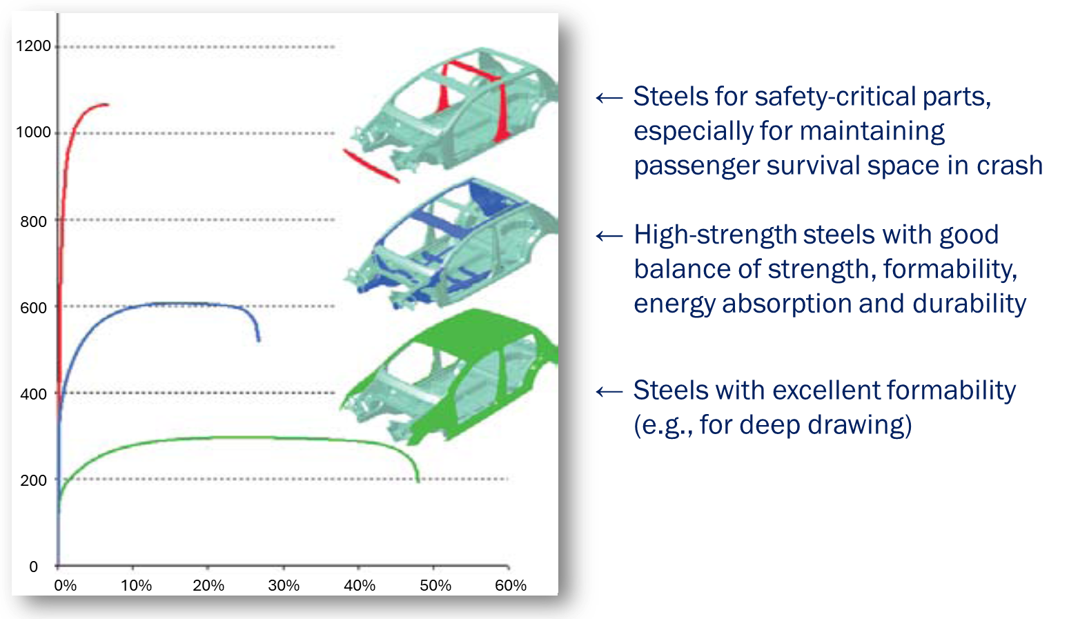
Automotive components are designed so that together they form a structure that meets all crash, safety, and functionality requirements, including those enforced by regional regulatory bodies and those set internally by car companies. Steel grade characteristics and properties guides the selection for specific applications, as shown schematically in Figure 2.C-5
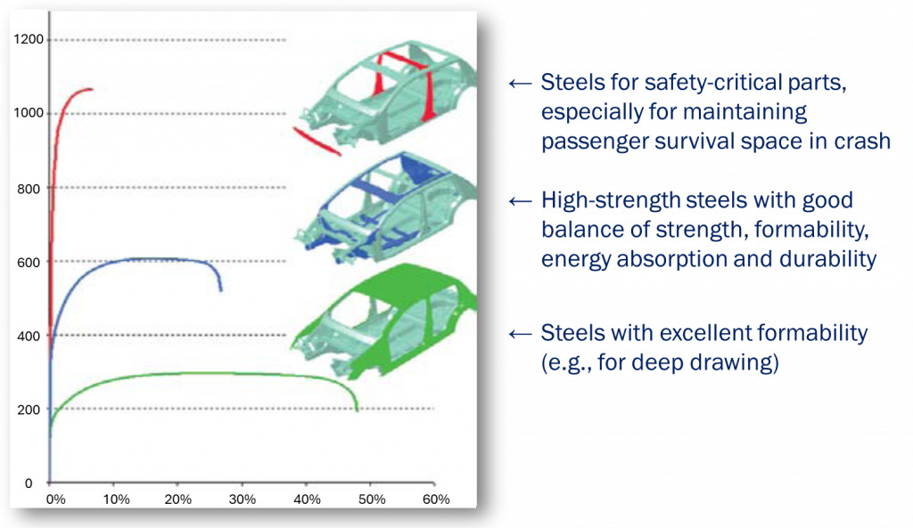
Figure 2: Comparison of stress-strain curves for different applications with body structures.C-5
Stiffness
Counter to the opinion of many, stiffness is not a function of a material’s strength. It is, however, a function of part geometry, elastic modulus and thickness. As an example of how part geometry influences stiffness, consider a sheet of paper. Stiffness improves dramatically once a crease is folded into it, yet the strength has not changed.
In automotive bodies, stiffness is related to handling and safety, as well as noise, vibration, and harshness characteristics.
A common strategy is to deploy AHSS for increased strength while decreasing weight by using thinner material. Casually applied, stiffness can suffer as a result. Geometry, specifically the moment of inertia of the cross-section about the primary load axis, plays a significant role in determining stiffness. The flexibility to adjust cross sectional and overall geometries allows for structural design solutions that more efficiently carry loads in the vehicle. The use of AHSS offers many advantages in this process because high work hardening rates increase formability, allowing for improved shapes for optimal efficiency. Additionally, AHSS typically possess high bake-hardening ability which can improve the final strength of a component after forming and paint-baking (curing).
Many lower-density metals like aluminium also have a lower elastic modulus than steels. To have an equally stiff component as one made of steel, the component from the lower-density material must have a combination of increased thickness or increased geometry. That increased thickness negates some of the perceived weight savings from the alternate material. Furthermore, lower-density materials must have sufficient ductility to be able to withstand the forming of the additional geometric features like in-part darts and beads and deeper draws associated with the increased shape required for stiffness improvement.
Forming and Manufacturability
Advanced high strength steels were developed partly to address the decreased formability typically associated with increased strength in conventional steels. AHSS grades are available at higher strength levels than conventional high strength steels, and have high work hardening and bake hardening characteristics that allow for increased formability and opportunities for additional optimization of part geometries. Both overall elongation and local elongation properties are important for formability, and global steelmakers have developed grades to address these needs.
Vehicle programs must balance performance, safety, fuel efficiency, affordability and the environment, while maintaining designs that are appealing to customers. Use of higher strength steels allows for a reduction in the sheet metal thickness and in turn vehicle mass. The increased ductility offered by Advanced High Strength Steels facilitates part consolidation also contributing to lower weight and manufacturing cost while providing an efficient way to increase component and vehicle stiffness.
Low-density materials like aluminium, magnesium and composites have widespread use in luxury class vehicles, where amenities, comfort, and speed are prioritized over affordability. Penalties for not meeting fuel economy and emissions mandates are easily absorbed in the sales price.
On mass-market vehicles, where per-unit emissions are multiplied over higher volumes, automakers target selecting the most efficient way to achieve the lowest total emissions.
Compared with the limited number of low-ductility steels available decades ago, the lower density materials would have offered an easy but costly path to lightweighting. Back then, since there were not that many high-strength options, vehicle crashworthiness was improved by increasing thickness.
However, increasing metal strength allows for a thickness reduction while maintaining crash performance. The substantially higher strength steels available today have sufficient ductility to form complex stampings from sheets thin enough to be weight-competitive with components formed from lower-density materials that must be made from higher thickness to have comparable stiffness.
The spectrum of steel grades commercially available today have:
- higher strength, greatly contributing to the crash-energy management approach.
- higher ductility that allows for additional shape to be formed into the component, also increasing stiffness and potentially allowing for part consolidation,
- higher modulus than aluminium or magnesium that inherently leads to a stiffer component.
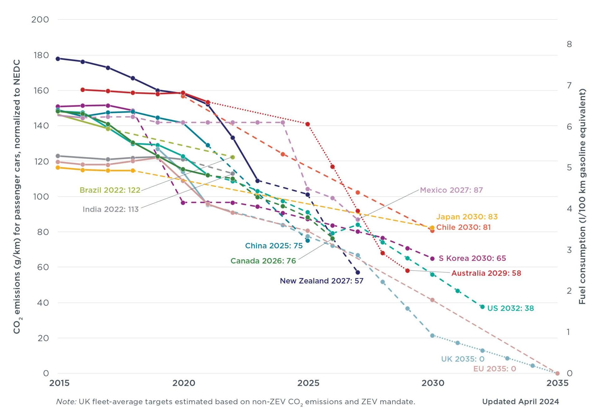
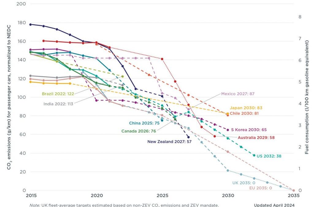
Recent years have seen an increased global sensitivity to tailpipe emissions, with Figure 1 highlighting regulations for passenger cars in different countries and regions. Many major markets have committed to fleet average emissions below 100 g CO2/km, and we’re on a negotiated global journey to Net Zero Emissions by 2050.
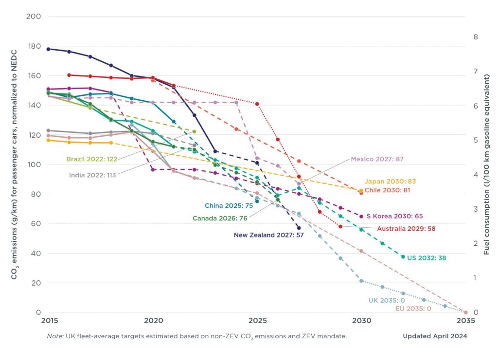
Figure 1: Passenger car emissions and fuel consumption targets, normalized to New European Driving Cycle I-2
The problem with the current regulation of automotive greenhouse gas (GHG) emissions is their focus solely on tailpipe emissions, produced from fuel combustion during vehicle use. The regulations ignore other significant sources of GHG emissions in the vehicle’s life cycle including vehicle production (including the emissions from material production) and treatment of the vehicle at the end of its useful life. This omission comes with serious risks. An unintended effect of this approach is an over-emphasis on vehicle lightweighting. While lightweighting can be an effective tool to reduce vehicle emissions, it must be done with a holistic knowledge of the implications related to the total vehicle life cycle GHG emissions.
Reducing vehicle mass decreases fuel consumption, which also reduces tailpipe emissions. This may, or may not, offset the increased production emissions from material production of the lower density materials. One possibility is that the reduction of emissions in the use phase results in overall lower emissions, but because of the trade-off between the use phase and production emissions, the result is not as low as predicted by a tailpipe-only metric – some of the use-phase savings is offset by the increased production emissions. Also possible is where the use phase savings and the production phase increase are approximately equal, resulting in no net savings at all. In the other extreme, the production emissions outweigh the use phase savings, resulting in the unintended consequences of an increase in the overall emissions. This last scenario is the very opposite of what government policy intends, but happens regularly when vehicles constructed with low density materials don’t reach their intended vehicle life.
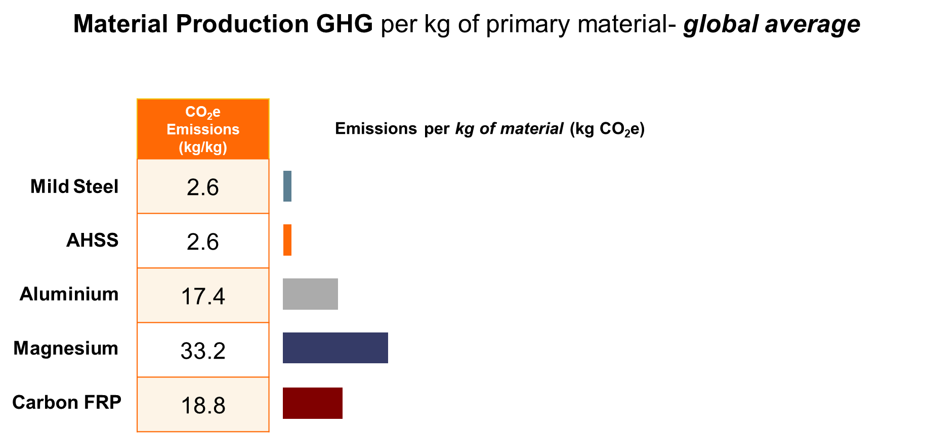
One of the perceived advantages to using materials of lower density is the expectation that they will result in lower GHG emissions. To illustrate why this is not true, consider the emissions from the material production stage of a typical automotive component. The mid-range GHG values for each material are taken from the above chart and then multiplied by the projected material weight that is required to make a hypothetical component. (The actual mass for an equivalent component varies based on the material used and the component design.)

Figure 2: Material average GHG emissions from primary production, in kg CO2e per kg of material.W-40
Furthermore, low-density materials create an offsetting emissions problem, as production of these materials is GHG-intensive, and therefore costly to the environment. The production of these alternative materials can produce 7 to 20 times more emissions than steel, as shown in Figure 2.

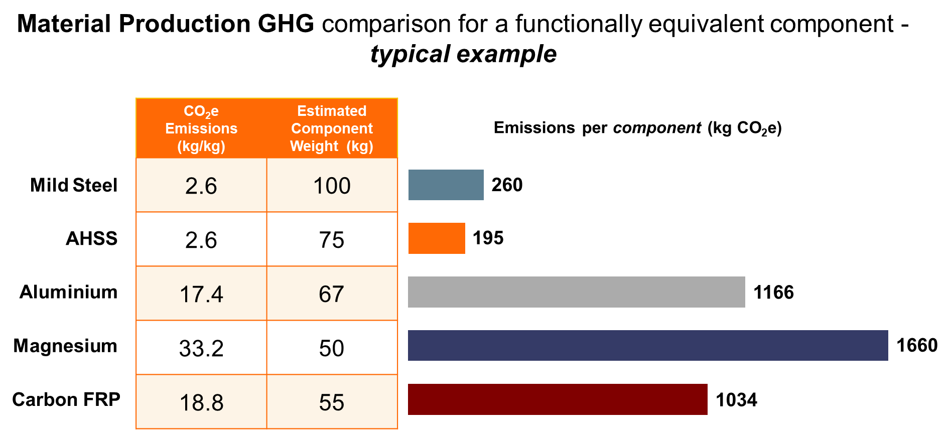
Figure 3: Material GHG emissions in kg CO2e for functionally equivalent generic components.W-40
Figure 3 shows that the use of lower density materials does not necessarily mean a reduction in greenhouse gas emissions. Although less weight is required for some alternative materials to achieve the same component functional performance, the emissions from the material production stage can still be many times higher than those of the baseline component. Therefore, the increase in material production emissions may outweigh the reduction in use phase emissions even after factoring in the mass savings benefit.
Vehicles are transitioning to alternative-energy powertrains and away from those based on fossil fuels. In these new-energy vehicles powered entirely by renewable electricity, emissions from the vehicle production stage, which includes material production, could account for as much as 95% of total emissions. In this scenario, the usage phase accounts for a mere 5% of the lifetime emissions. This is the opposite of what is found with vehicles having conventional Internal Combustion Engine (ICE) powertrains. For this reason, use of low GHG material such as steel becomes even more important as the world moves towards a renewable future.
Life Cycle Assessment
Life Cycle Assessment (LCA) is an environmental accounting methodology that considers a product’s entire life cycle, with cradle-to-grave assessments typically including impacts from raw material extraction and production (manufacturing phase), through its useful life (use phase), and to the end-of-life disposal or recycling of the product (end-of-life phase). It also takes into account the full life cycle of energy sources used across all lifecycle phases. This process illuminates any potential trade-offs between phases and highlights the true environmental impact, beyond the focus on tailpipe-only emissions.
Recent years have seen a greater adoption of using Life Cycle Assessment to assess a vehicle’s true environmental impact rather than solely focusing on what comes out of the tailpipe. LCA accounts for the total emissions including those coming from material production, vehicle use, and the chosen end-of-life path. The principles, framework, requirements and guidelines for Life Cycle Assessment are laid out in international standards ISO 14040I-3 and ISO 14044I-4.
Most major OEMs utilize some form of life cycle thinking or LCA, recognizing its importance and effectiveness in product and process design. Material producers also accept and use LCA. Together with many of their member companies, the trade associations of the steel, aluminium, and plastics industries are among the most active members of the global LCA community.
The European Union requires accounting for embedded lifecycle emissions. Following a phase-in period, there will be monetary penalties assessed against companies not providing this information. These requirements will drive OEMs to demand pertinent details from all of their material suppliers.
Environmental policies target achieving a total net reduction in emissions, including GHG (measured in carbon dioxide equivalents, or CO2e, that is a measure of all greenhouse gases attributable to a product that affect global warming potential. Thus, CO2e includes gases other than CO2.
Properly applied, LCA enables automakers to ensure that improvements in one phase are not offset by worse performance in another phase. This assessment of potential trade-offs is critical to environmental improvement. For example, if the increase in production emissions of a lightweight material is greater than the decrease in use phase emissions, vehicle light-weighting in this manner counter-productively increases total emissions.
LCA can be used to assess a broad array of environmental impacts beyond the global warming potential of greenhouse gases, including acidification, ecotoxicity, and ozone depletion.
The Path To Net Zero Emissions
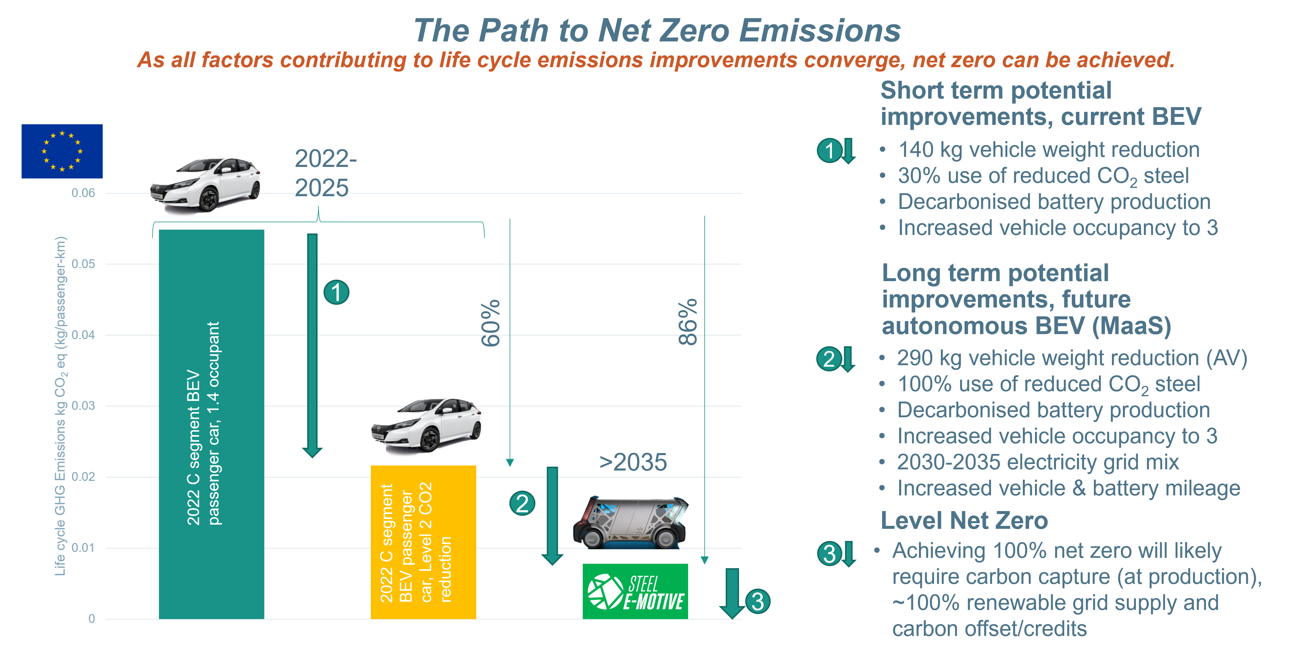
Fully autonomous Mobility as a Service vehicles such as the Steel E-Motive concept have the potential to address the ongoing and future requirements for decarbonisation of passenger transportation. Figure 4 shows the emissions walk-down beginning with a present-day C-sized BEV operating as a taxi.
Near term, a 60% reduction in Life Cycle emissions can be realized by an increased use of reduced CO2 steel and decarbonized battery production, along with an increased use of ride-sharing. Through 2035, as all available emissions reduction strategies are deployed – including autonomous MaaS vehicles with increased occupancy and extended vehicle and battery lives – an 86% reduction in emissions from a 2022 baseline is feasible.
Achieving Net Zero post 2035 requires carbon capture technologies, 100% renewable grid supplies, and carbon offsets or credits.
Each of these steps are described in detail within the Steel E-Motive Engineering Report.
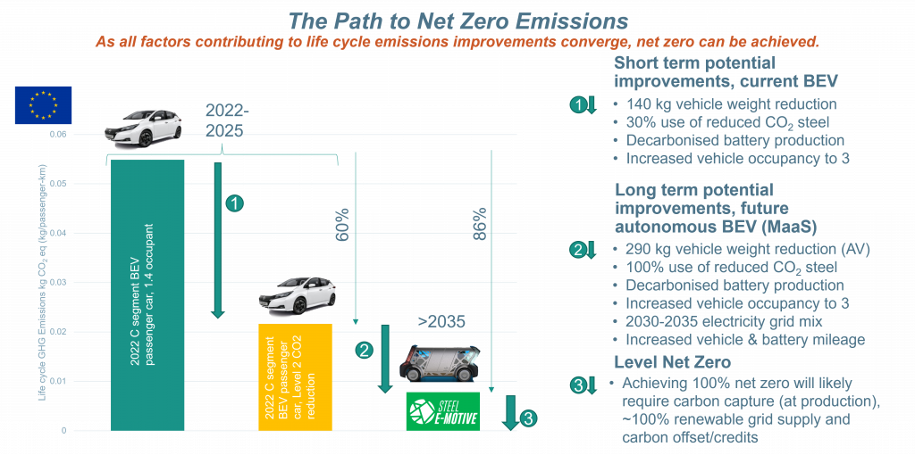
Figure 4: The Path to Net Zero Vehicle Emissions
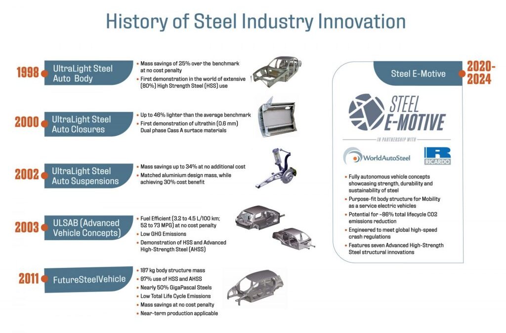
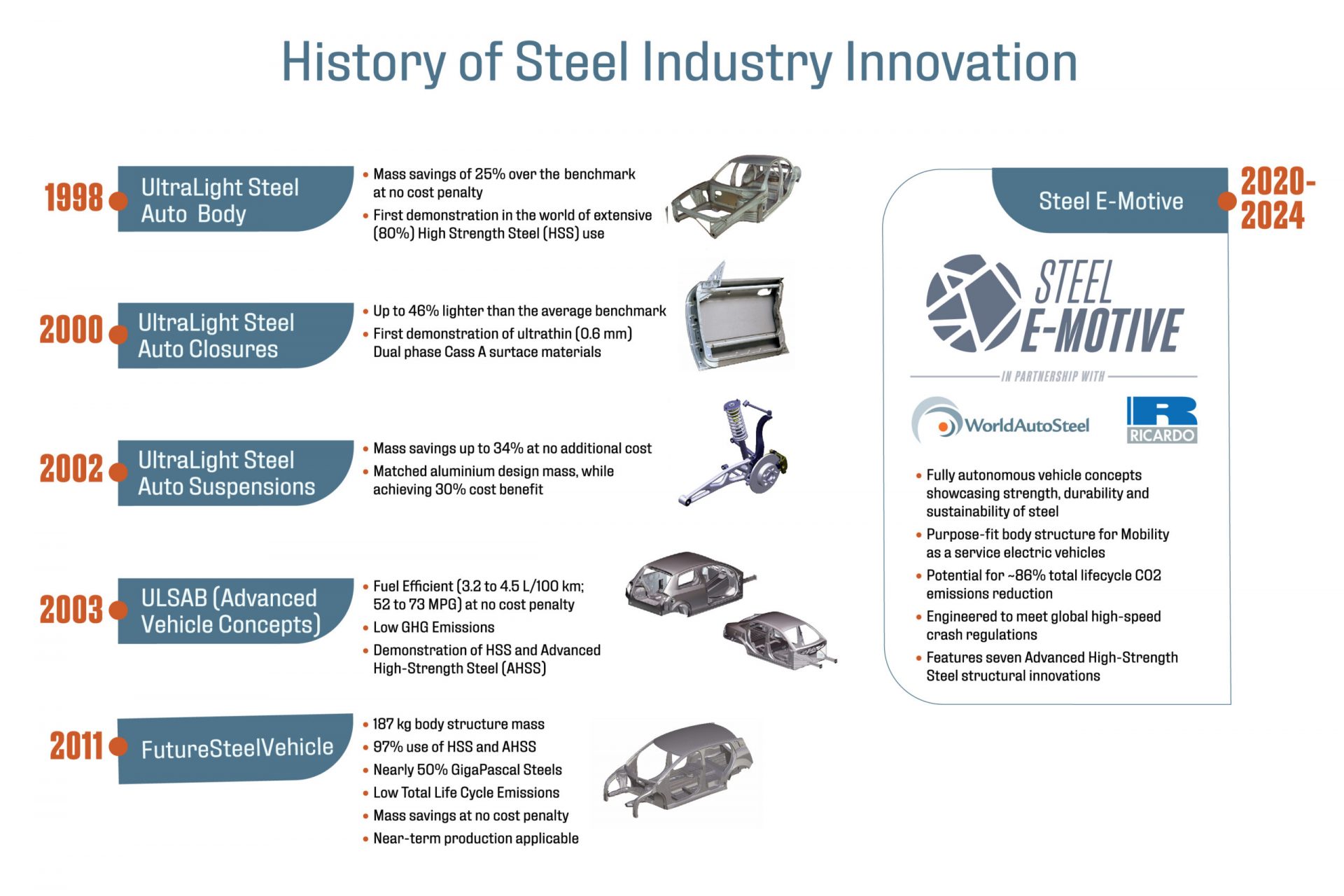
A consortium of 35 global sheet steel producers representing 22 countries began the UltraLight Steel Auto Body (ULSAB) program in 1994 with the goal of designing a lightweight steel auto body structure that would meet existing and proposed safety and performance targets.
The body-in-white (BIW) unveiled in 1998 validated the design concepts of the program, with the demonstration hardware achieving a 25 percent reduction of vehicle body structure weight at no cost penalty compared to conventional steel body structures of that time. ULSAB proved to be lightweight, structurally sound, safe, executable, and affordable.
ULSAB received wide acceptance by the automotive industry, to the point where is spawned three other steel consortia projects covering closures UltraLight Steel Auto Closures (ULSAC), suspensions UltraLight Steel Auto Suspensions (ULSAS) and full vehicle design UltraLight Steel Auto Body – Advanced Vehicle Concepts (ULSAB-AVC). Each one used an increasing percentage of high strength steels and Advanced High-Strength Steels (AHSS), along with advanced fabrication technologies such as tailored blanks, hydroformed tubes and continuous laser welding, each enhancing structural efficiency. At that time, AHSS use was in its infancy, and provided combinations of strength and ductility that were never-before realized, while still allowing for use of existing stamping and assembly fabrication equipment and production methods.
By 2008, the steel company consortium evolved into WorldAutoSteel, which began another program called FutureSteelVehicle (FSV), where steel members accelerated the development and deployment of new AHSS grades, further stretching the envelope for strength and ductility levels. FutureSteelVehicle took automotive steel applications to GigaPascal strength AHSS and added the dimension of designing for reduced life cycle emissions. W-11
FutureSteelVehicle featured clean-sheet steel body structure designs for advanced powertrains, including full battery electric vehicle (BEV), plug-in hybrid and hydrogen fuel cells – and demonstrated that sophisticated steel grades combined with engineering optimisation could reduce mass by more than 35 percent over a benchmark vehicle and reduced total life cycle emissions by nearly 70 percent. This was accomplished while meeting a broad list of global crash and durability requirements and enabled five-star safety ratings while avoiding high-cost penalties for mass reduction.W-11 More information about the FutureSteelVehicle is found here with greater details shown here: FutureSteelVehicle Reports
Steel E-Motive represents fully autonomous electric ride sharing vehicle concepts showcasing the strength and durability of steel with a critical focus on sustainability for reaching net zero emissions targets. The results are sustainable comfortable, safe and affordable body structures that support automakers in the continued development of Mobility as a Service (MaaS) ride sharing models. Some highlights of the Steel E-Motive program can be found here, with the entire program documented at https://SteelEMotive.world.
Another consortium, the Auto/Steel Partnership (A/SP) engages in research and demonstrates the value of AHSS through several programs. One such project, the Lightweight Front End Structure, used a holistic approach to meet goals of more than 20 percent weight reduction while maintaining crash worthiness.J-26 A-79 Manufacturability was examined and emphasized throughout this project. Another key program, the Future Generation Passenger Compartment project, examined the effect of mass compounding.A-80 U-15
Over the years since ULSAB, the successes of AHSS have motivated steel companies to continue research on both new types and grades of AHSS and to then bring these new steels to production. Essential for the growing use of AHSS has been the simultaneous development of new processes and equipment to produce and form the material. Some of these processes are described throughout these guidelines.

Figure 1: WorldAutoSteel Vehicle Development Programs.
Blog, homepage-featured-top, main-blog, News
The transportation industry’s contribution to greenhouse gas (GHG) emissions and global warming is well documented and understood. Vehicle OEMs, fleet operators, and transport users all have responsibilities to reduce environmental impacts on the planet and contribute to meeting global emissions regulations.
Mobility as a Service (MaaS) solutions like WorldAutoSteel’s flaghip Steel E-Motive (SEM) program have the potential to contribute to a reduction in GHG emissions, helping to achieve these global targets and specific policy objectives. The Steel E-Motive engineering report, released in 2023, addresses the impact of emissions reduction using Life Cycle Assessment, with key results summarized in this article.
Introduction to Life Cycle Assessment
Life Cycle Assessment (LCA) is a methodology that evaluates the environmental impact of a product across its entire lifecycle. By understanding the impact across the entire vehicle life cycle, vehicle manufacturers evaluate trade-offs and assess the net impact of the product they’re using.
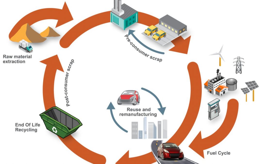
Cradle-to-grave assessments utilize a boundary that includes impacts from the production phase (including raw material extraction and vehicle production), the use phase (including fuel or electricity as well as consumables like tires and fluids) and the end-of-life phase, which could include disposal and/or recyling of the product, as shown in Figure 1. We applied LCA throughout the development of the SEM concept.
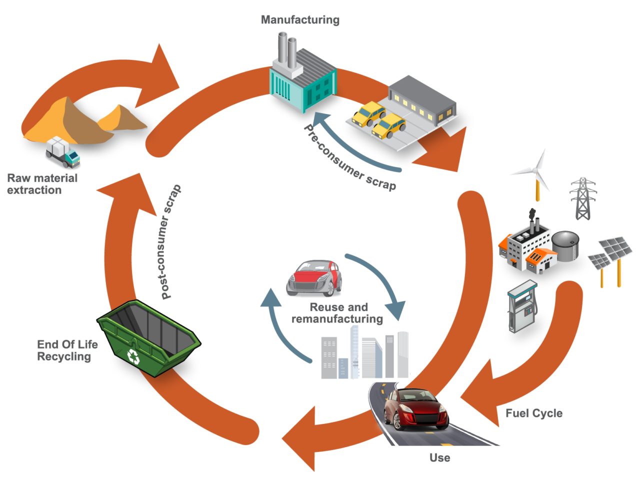
Figure 1. SEQ Figure \* ARABIC 1 Life Cycle Assessment, considering the entire life of the vehicle, from raw material extraction to end of life
LCA can cover a range of environmental impacts; however, for the SEM program, we focused on GHG emissions through the GWP-100 indicator and total energy consumption using Cumulative/Primary Energy Demand and Fossil Energy Consumption indicators.
Reference Taxi (Baseline) Vehicle
A key consideration in LCA calculations is establishing an appropriate reference vehicle. For this program, the following criteria was used:
- Present day (~2020) battery electric vehicle (BEV) operating in taxi mode with a driver and one occupant with vehicle/battery lifetime assumptions of 300,000km, and use of 100 percent conventional steel/aluminum.
- Vehicle end-of-life methodology using the Avoided Burden Approach, where recycled metals are assumed to displace equivalent quantities of their virgin counterparts and assigned corresponding emission and energy demand credits.
- Assumption of 50 percent pyrometallurgical recycling for the battery packs.
- Estimated reference taxi vehicle curb weight using the statistical reference data study (Figure 2), resulting in an estimated curb weight of 1,949kg.
- Material utilization based on data from a similar vehicle specification, as shown in Figure 3.
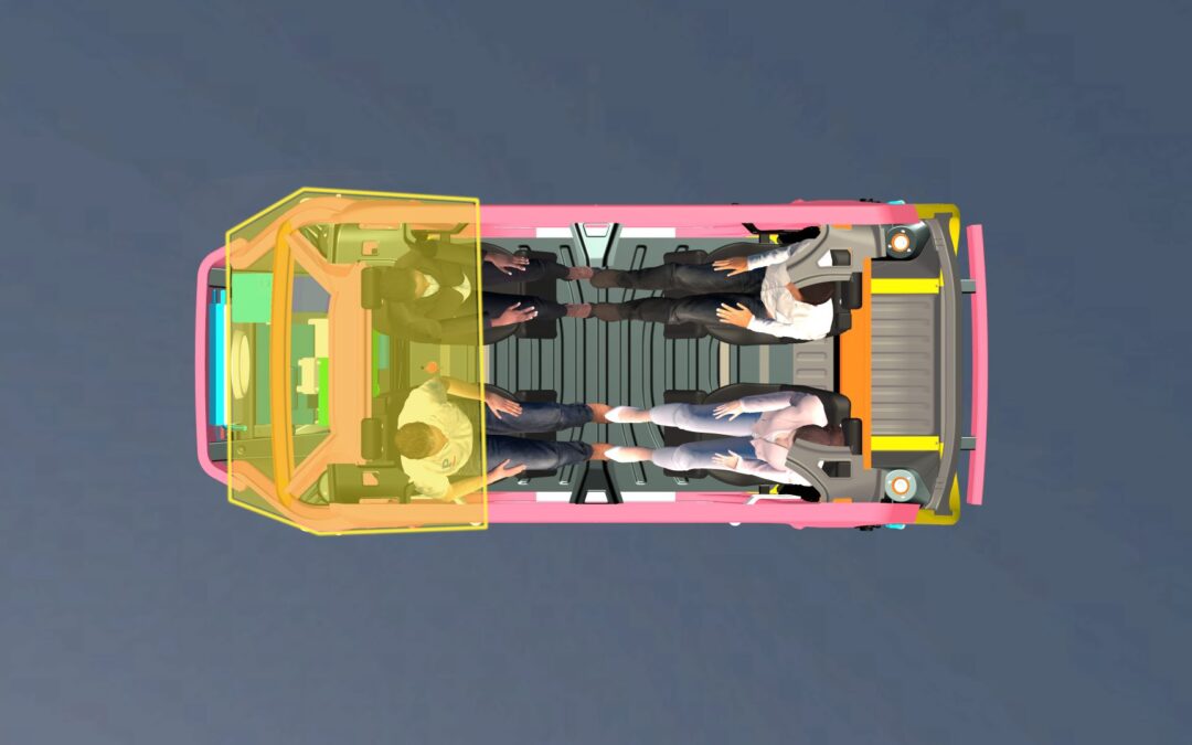
- Vehicle occupancy rate assumptions of 1.4, based on a combination of both “empty” and passenger-carrying journeys.
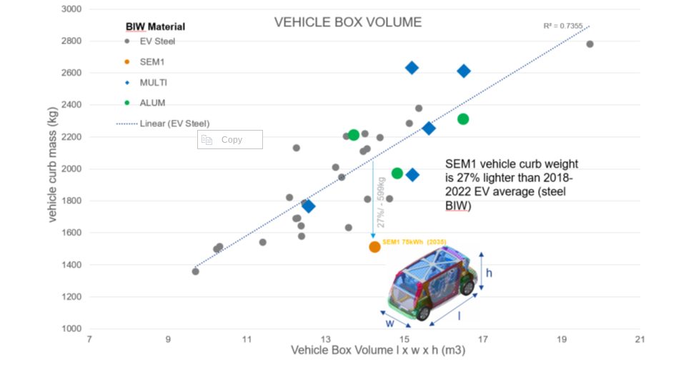
Figure 2. Vehicle curb weight versus box volume comparison. Reference vehicle data; source www.a2mac1.com
Steel E-Motive “Default” Vehicle
SEM vehicle life cycle calculations assume a hypothetical 2030 manufacture and start-of-operation date of 2030 to 2035. We updated the electricity grid supply mix to include the average of the International Energy Agency (IEA) scenario estimates for 2030 and 2040.
- We applied the nominal SEM1 vehicle curb weight of 1,512kg in the LCA model, and updated the vehicle Bill of Materials.
- As with the reference vehicle, we adopted the Avoided Burden Approach as the default for end-of-life calculation.
Life Cycle Assessment Results
Figure 3 below highlights absolute calculated life cycle GHG emissions, in units of kgCO2e/ passengerꞏkilometer studied, with the individual contributions of vehicle manufacturing, vehicle use, and end-of-life phase presented.
The analysis evaluated two reference/baseline conditions and nine SEM sensitivity studies, see Figure 4. These included alternative assumptions on LCA end-of-life modeling methodology, lifetime vehicle activity (and battery lifetime), alternative operational energy consumption sensitivities, sensitivities on the use of ‘green’ steel, and vehicle occupancy rates.
The accompanying pie chart shows the breakdown and contributions to the vehicle manufacture GHG for the baseline SEM scenario (2).
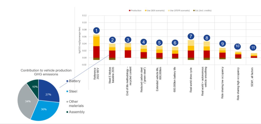
Figure 3. SEQ Figure \* ARABIC 2 life cycle assessment GHG results
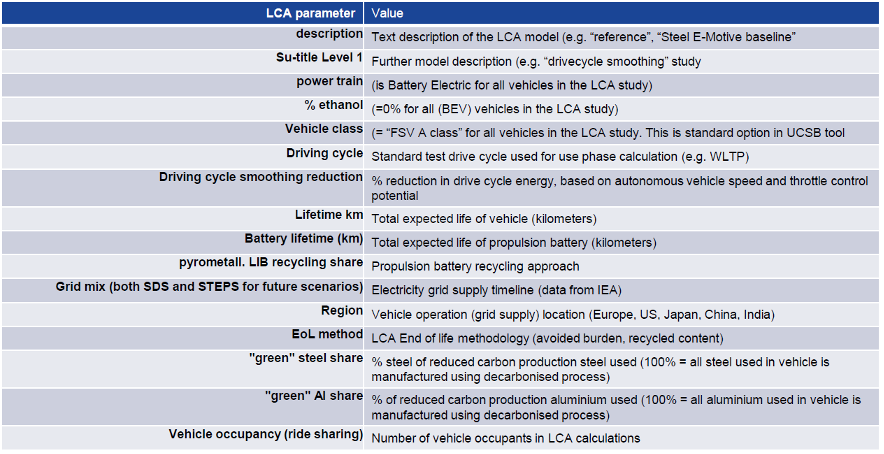
Figure 4. Reference/baseline conditions and SEM sensitivity studies
Life Cycle Assessment Conclusions
Based on the parameters outlined, applying LCA to SEM concept demonstrated the designs’ potential to reduce lifecycle greenhouse gas emissions by up to 86 percent compared to a present-day battery electric vehicle operating as a taxi.
This potential can be realized by adopting the following measures:
- Reducing vehicle production and manufacturing embedded emissions by utilizing 100 percent reduced carbon (“green”) steel
- Improving battery technology and increasing the use of renewable electricity in battery manufacturing; as well as increasing/improving battery recycling
- Ensuring the vehicle weight of autonomous vehicles is managed, and the potential weight reduction benefits realized and implemented. The SEM body structure and battery housing demonstrate good weight efficiency.
- Increasing the overall lifespan of the vehicle and battery. The fatigue and durability properties of AHSS can enable enhanced vehicle lifetime. The SEM battery design allows easy replacement of specific modules, enabling an overall extended battery life.
- Autonomous vehicle control smooths the driving cycle. The vehicle acceleration and deceleration rates can be optimized to match the driving conditions and road topography, reducing energy consumption and subsequent GHG emissions.
- Increasing passenger occupancy rates to at least three per vehicle via MaaS.
The projected net GHG emissions for the SEM vehicle operating with the flexibilities described above already represent a significant reduction when compared to the current baseline.
Achieving net zero emissions would require additional measures like offsetting manufacturing impacts (e.g., through compensatory credits from atmospheric carbon capture and storage) and transitioning to a 100 percent renewable electricity grid.
Moving Toward Net Zero
Taking a Life Cycle Assessment approach to the SEM concept demonstrates the possibilities for engineering future mobility vehicles that continue to move us closer to a net zero future. For more information about the Steel E-Motive program, download the engineering report here: https://bit.ly/SEM_Eng_Report

Thanks go to Russ Balzer for his contribution of this article to the AHSS Insights blog. As.technical director at WorldAutoSteel, he leads technical programs and oversees the organization’s work in research, modeling, and advocacy for Life Cycle Assessment in the automotive sector. An LCA Certified Professional through the American Center for Life Cycle Assessment (ACLCA), he also acts as the WorldAutoSteel liaison to the worldsteel LCA Expert Group.
Blog, main-blog, News
As robotaxi companies in the USA prepare to launch their autonomous vehicles in more cities, safety is in the spotlight again. And rightly so. Autonomous vehicle safety challenges must be addressed and with the Steel E-Motive Level 5 autonomous concept, we did that.
Many autonomous mobility service companies have relied on two factors when developing their vehicles: active safety systems which help the vehicle avoid or mitigate the extent of a crash, and a maximum vehicle speed limit, which will reduce the extent of injuries to the occupants.
But the fact is that these vehicles are going to be out in mixed-mode traffic situations. There will be accidents – however much we all attempt to do everything possible to avoid them. When we developed the Steel E-Motive (SEM) body structure concepts for fully autonomous ride-sharing electric vehicles, we agreed on two basic principles – that these vehicles would operate at high speeds (top speed of 130 kph) in mixed mode traffic conditions, and that we, therefore, needed to engineer passive safety structures that met global high-speed crash requirements to protect occupants and the battery system in these use-case conditions. In this process, we discovered that no other provider of autonomous ride-sharing electric vehicles had fully shared details of passive safety structures engineered to those same high-speed crash standards. Autonomous vehicle safety had been addressed only on a limited basis.
Fortunately, our vehicle design process benefitted from a massive portfolio of modern advanced high-strength steels (AHSS) available through member companies of WorldAutoSteel. Steel E-Motive (SEM) was developed to show how AHSS can enable sustainable, comfortable, economical, and safe ride-sharing vehicles by 2030.
The AHSS Extended Passenger Protection Zone provides excellent cabin intrusion protection and ultimately lower risk of injury. PHS provides formability for challenging geometries, and Martensitic steel (MS) provides the strength to limit intrusion.
Visit this link to download the full engineering report: Steel E-Motive
The result is one of the first robotaxis to fully detail and report compliance to global high-speed safety standards. In developing Steel E-Motive, we targeted conformity with seven US crash standards, including US NCAP (New Car Assessment Program) IIHS and FMVSS (Federal Motor Vehicle Safety Standards) front, side, and rear impact tests while also assessing performance against worldwide protocols, including NHTSA (US) Euro NCAP (European) and China’s GB 38031 standard for battery protection.
As an example, Steel E-Motive achieves the highest IIHS rating of “good.” This is particularly important as IIHS (the US-based Insurance Institute for Highway Safety) is highly regarded for its dedication to reducing deaths, injuries, and property damage from motor vehicle crashes.
Most production vehicles use new generation, advanced high-strength steels, and technologies. We had no fewer than 64 AHSS materials to select from, enabling us to choose exactly the right steel for every need and purpose in the vehicle, including safety protection. These make a car stronger, more fuel efficient, and safer.
Nearly all vehicles on the road today are made of steel because it has the broadest range of properties while being the most affordable structural material for designing safe vehicles. Steel has a unique capacity to absorb an impact, and, therefore, to diffuse crash energy. It also becomes harder when it’s crushed, which means it will become stronger on impact, retarding further penetration into the vehicle’s passenger zone.
Taking on Autonomous Vehicle Safety Challenges
Here is an outline of how we designed steel’s benefits into the Steel E-Motive (SEM) concept when considering front and side crashes.
SEM features a high-strength front protection zone, which reacts to the crush loads and minimizes intrusion for the occupants in front crashes. The crush zones have been engineered to decelerate the vehicle progressively. The longitudinal mid rails, featuring tailor-welded blanks fabricated with Dual Phase steels, are tuned to give a lower deceleration pulse into the passenger cabin to minimize injury threat. The side crush rails are designed to minimize intrusion into the cabin for occupant protection. Finally, a novel design geometry and Press Hardened Steels enable the new glance beam architecture to force the vehicle off of the Small Offset barrier; the resulting “glance-off” achieves significantly reduced crash energy and pulse into the passenger cabin.
When considering side crashes, we engineered the body structure for the IIHS 60kph deformable barrier test and 30kph side pole test, assessing both occupant and battery protection and achieving the IIHS “good” performance rating. Our side structures are comprised of a large one-piece tailor-welded door ring fabricated with press hardened steels, the TRIP steel B pillar housed in the side scissor doors, and a roll-formed hexagon rocker beam fabricated with Dual Phase steel.
These attain a very safe design, giving good levels of protection for both the occupants and battery modules, exceeding 30mm intrusion clearance at critical measurement points.
SEM was also engineered for rear crash and roof crush, and once again, the robust steel-intensive architecture exceeds crash standard requirements.
Electric-powered vehicle sales are accelerating, reflecting industry investment, and will soon achieve market domination from the combustion engine. In megacities, where congestion, pollution, and exorbitant vehicle ownership costs reign, Autonomous cars will replace drivers, and ride-sharing will become the norm. As we look into the future and recognize the need for these vehicles to offer comfortable, safe, affordable, and sustainable transportation, we will still be designing them by harnessing the unique properties of steel.
Visit this link to download the full engineering report: Steel E-Motive