Drawing is the sheet metal forming process where the punch that creates the part shape forces the sheet metal to pull in from the flange area. In contrast with stretch-drawing or stretch forming, little metal thinning occurs in pure drawing. There is not a generally accepted definition for the term “deep drawing,” although some references describe it as when the depth of draw is greater than the diameter.
Drawability, or the ability for a sheet metal to be drawn into a cup, is assessed by the cup drawing test to measure the Limiting Draw Ratio, or LDR. Here, a cylindrical punch contacts and then pushes a circular blank into the die (Figure 1). The ratio of the largest blank diameter successfully drawn into a cup to the punch diameter used for drawing is the LDR.

Figure 1: In the cup drawing test, a punch deforms a circular blank into a cylindrical cup. The largest ratio of blank diameter to punch diameter successfully drawn into a cup is the Limiting Draw Ratio (LDR).
In the LDR test, metal in the circular blank flows over the die radius and into the cup wall. The metal movement from the flat blank to the vertical sidewalls is the only metal movement which happens, since there is no metal flow within the flat bottom region.
As shown in Figure 2, the flange of the circular blank undergoes radial tension and a circumferential compression as the flange moves in a radial direction towards the circular die radius in response to a pull generated by a flat bottom punch. Blank holder pressure is set to prevent buckles in the blank.
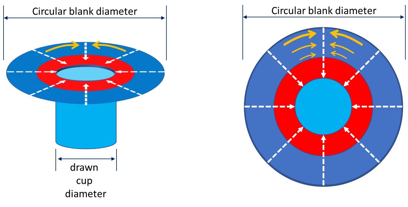
Figure 2: Tension and compression in a drawn cup. Dashed white arrows indicate the radial tension created during cup forming; orange arrows indicate flange compression as a greater amount of metal feeds into progressively smaller regions.
The steel property that improves cup drawing or radial drawing is the normal anisotropy or rm value. Values greater than 1 increase in the Limiting Draw Ratio. In contrast, the LDR is insensitive to the strength of the steel and the n-value. High-strength steels with UTS greater than 450 MPa and hot-rolled steels have rm values approximating one and LDR values between 2.0 – 2.2. Therefore, DP and HSLA steels have similar LDR values. However, TRIP steels have a slightly improved LDR deep drawability.T-2 Since the transformation of retained austenite to martensite is influenced by the deformation mode (Figure 3), the amount of transformed austenite to martensite generated by shrink flanging in the flange area is less than the plane strain deformation in the cup wall. This difference in transformation from retained austenite to martensite makes the wall area stronger than the flange area, thereby increasing the LDR. The benefit of the increased LDR is seen in Figure 4 which shows cups formed from different grades having the same tensile strength.

Figure 3: The cup wall in plane strain strengthens more than the shrink flange due to increased amounts of transformed martensite in TRIP steels.T-2
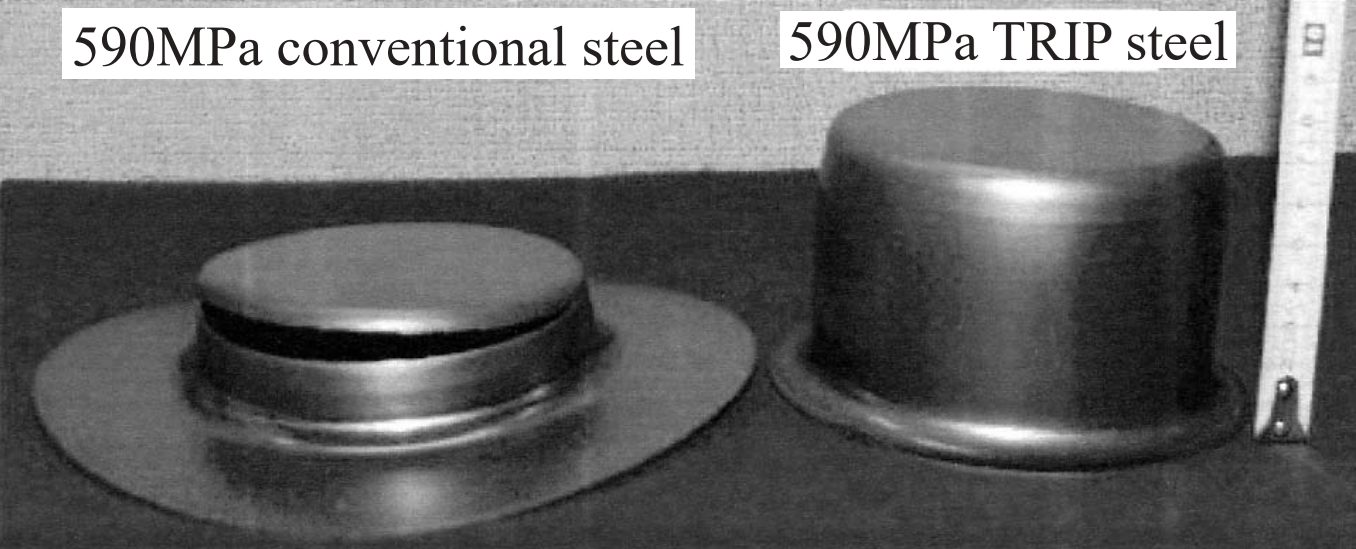
Figure 4: Cups formed from 590MPa tensile strength steels, highlighting greater draw depths possible with TRIP steels.T-2
In a study of different gradesC-9, laboratory cup drawing experiments show an approximate LDR of 2.0 – 2.2 for the DP steels tested (Figure 5). Note that a doubling of the yield strength has no effect on the LDR. An increased rm value of mild steel created a small increase in LDR over DP steel. The LDR of the MS (martensitic) steel evaluated may have been impacted by the reduced bendability going over the die radius. Figure 6 shows the cup draw depths possible for the grades reported in Figure 5.S-26
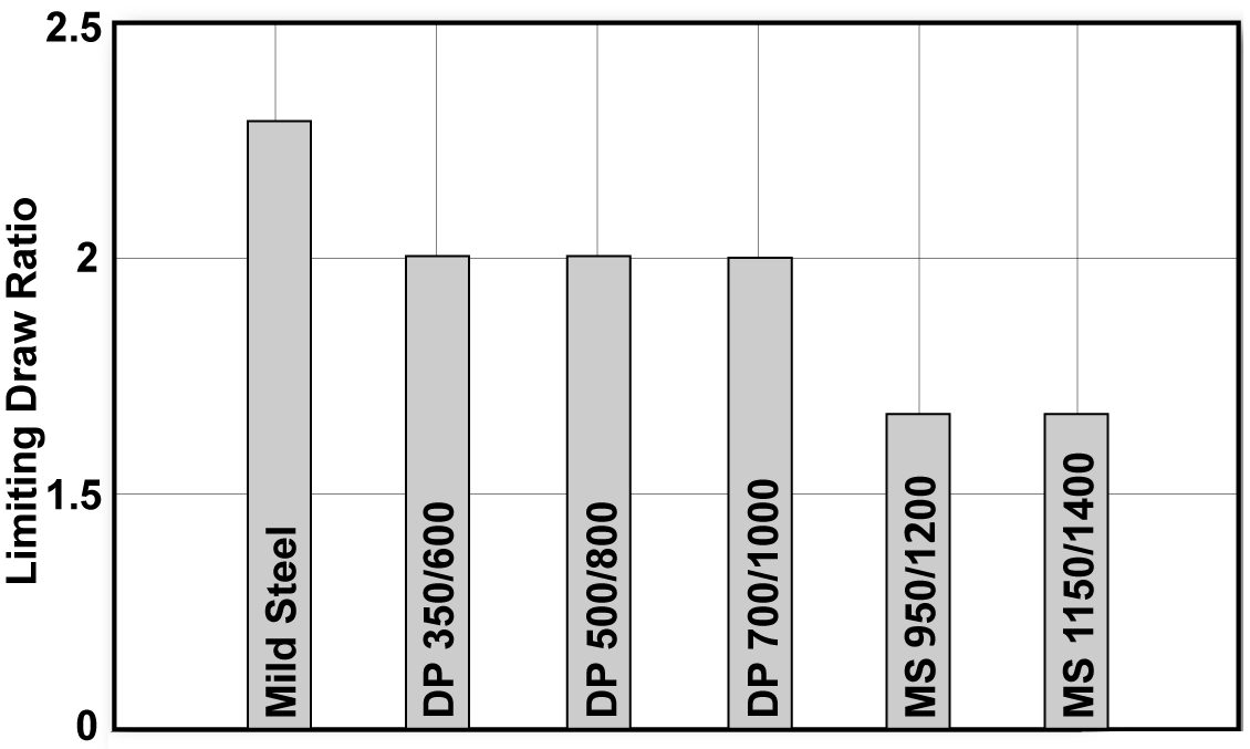
Figure 5: LDR tests for Mild, DP, and MS steels.C-9
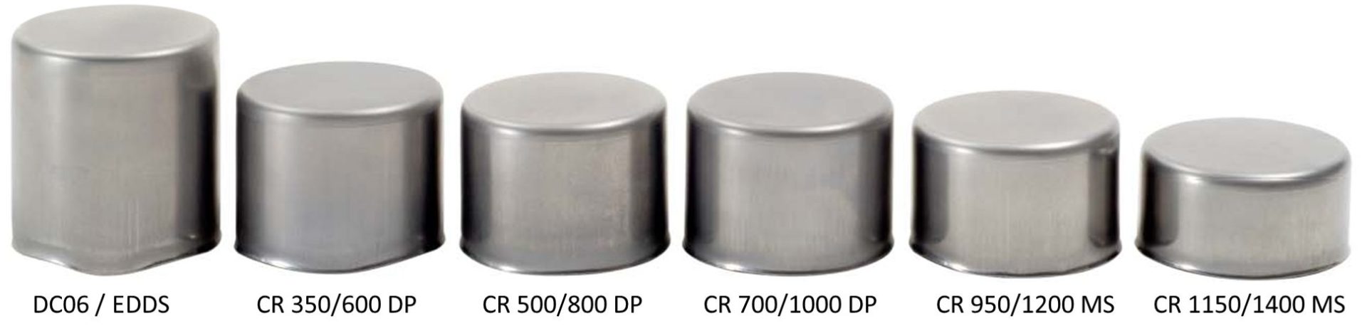
Figure 6: Cups used in the testing reported in Figure 5.S-26
Even though r-value is the only steel property influencing the formability of drawn flat-bottom cups through its relationship with LDR, not all cups have flat bottoms. Some have hemispherical or other configurations for bottoms. Adding a dome-like shape to the cup results in a more complex forming operation which is now sensitive to material properties like n-value and microstructures.
Corners of box-shaped stampings and the ends of closed channels contain design features similar to drawn cups, providing insight on an analytical approach.
- The four corners of a box-shaped drawn panel should each be analyzed as one-quarter of a cup. Buckles forming in the binder area indicate compressive flow. The corners of the blank will form the same as a deep drawn cup.
- The side walls are formed by metal flowing from the binder across the die radius. The term for this metal flow is bend-and-straighten.
In summary, higher LDR values are achievable in steels with greater values of the normal anisotropy ratio, rm. The absolute value of the LDR, however, also depends on the lubrication, blank holder load, die radius and other system inputs. Figure 7 compares a higher viscosity lubricant on the left with a lower viscosity lubricant on the right.S-26 Die radii need to be balanced: large radii promotes metal flow and may lead to wrinkles, while small radii restricts metal flow and may lead to splits.
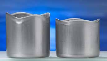
Figure 7: The influence of lubricant viscosity on drawing. The cup formed with the higher viscosity lubricant is on the left.S-26