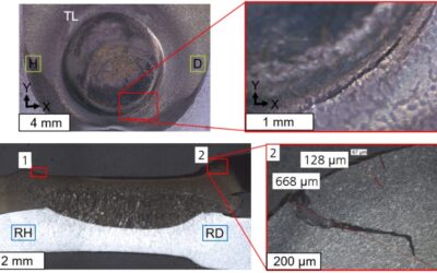
How Advanced High-Strength Steels Solve Cold Stamping Challenges in Automotive Body Structures Introduction In the automotive industry, manufacturing complex, high-strength deep-drawn parts using cold forming processes can create new challenges not previously...
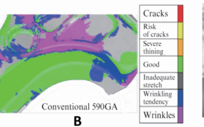
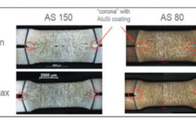
Case Studies in AHSS Alloy Selection
read more