- Metallurgy of Martensitic Steels
- Case Study: Using Martensitic Steels as an Alternative to Press Hardening Steel – Laboratory Evaluations
- Case Study: Martensitic Steels as an Alternative to Press Hardening Steel – Automotive Production Examples with Springback Mitigation Strategies
Metallurgy of Martensitic Steels
Martensitic steels are characterized by a microstructure that is mostly all martensite, but possibly also containing small amounts of ferrite and/or bainite (Figure 1 and 2). Steels with a fully martensitic microstructure are associated with the highest tensile strength – grades with a minimum specified tensile strength of 1700 MPa are commercially available, and higher strength levels are under development.

Figure 1: Schematic of a martensitic steel microstructure. Ferrite and bainite may also be found in small amounts.

Figure 2: Microstructure of MS 950/1200
To create MS steels, the austenite that exists during hot-rolling or annealing is transformed almost entirely to martensite during quenching on the run-out table or in the cooling section of the continuous annealing line. Adding carbon to MS steels increases hardenability and strengthens the martensite. Manganese, silicon, chromium, molybdenum, boron, vanadium, and nickel are also used in various combinations to increase hardenability.
The advent of water quenched lines facilitated the ability to reduce the amount of alloying additions, which has an associated benefit of producing a microstructure that is less susceptible to delayed cracking.
These steels are often subjected to post-quench tempering to improve ductility, so that extremely high strength levels can be achieved along with adequate ductility for certain forming processes like Roll Forming.
Figure 3 shows MS950/1200 compared to HSLA. Engineering and true stress-strain curves for MS steel grades are presented in Figures 4 and 5.
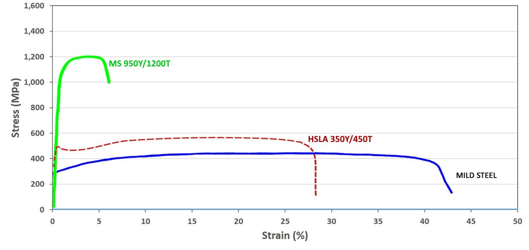
Figure 3: A comparison of stress strain curves for mild steel, HSLA 350/450, and MS 950/1200.

Figure 4: Engineering stress-strain curves for a series of MS steel grades.S-5 Sheet thicknesses: 1.8 mm to 2.0 mm.

Figure 5: True stress-strain curves for a series of MS steel grades.S-5 Sheet thicknesses: 1.8 mm to 2.0mm.
In addition to being produced directly at the steel mill, a martensitic microstructure also can be developed during the hot stamping of press hardening steels.
Examples of current production grades of martensitic steels and typical automotive applications include:
| MS 950/1200 | Cross-members, side intrusion beams, bumper beams, bumper reinforcements |
| MS 1150/1400 | Rocker outer, side intrusion beams, bumper beams, bumper reinforcements |
| MS 1250/1500 | Side intrusion beams, bumper beams, bumper reinforcements |
Some of the specifications describing uncoated cold rolled 1st Generation martensite steel (MS) are included below, with the grades typically listed in order of increasing minimum tensile strength. Different specifications may exist which describe hot or cold rolled, uncoated or coated, or steels of different strengths. Many automakers have proprietary specifications which encompass their requirements.
- ASTM A980M, with Grades 130 [900], 160 [1100], 190 [1300], and 220 [1500]A-23
- VDA 239-100, with the terms CR860Y1100T-MS, CR1030Y1300T-MS, CR1220Y1500T-MS, and CR1350Y1700T-MSV-3
- SAE J2745, with terms Martensite (MS) 900T/700Y, 1100T/860Y, 1300T/1030Y, and 1500T/1200YS-18
Case Study: Using Martensitic Steels
as an Alternative to Press Hardening Steel
– Laboratory Evaluations
Martensitic steel grades provide a cold formed alternative to hot formed press hardening steels. Not all product shapes can be cold formed. For those shapes where forming at ambient temperatures is possible, design and process strategies must address the springback which comes with the high strength levels, as well as eliminate the risk of delayed fracture. The potential benefits associated with cold forming include lower energy costs, reduced carbon footprint, and improved cycle times compared with hot forming processes.
Highlighting product forms achievable in cold stamping, an automotive steel Product Applications Laboratory formed a Roof Center Reinforcement from 1.4 mm CR1200Y1470T-MS using conventional cold stamping rather than roll forming, Figure 6. Using cold stamping allows for the flexibility of considering different strategies when die processing which may result in reduced springback or incorporating part features not achievable with roll forming.

Figure 6: Roof Center Reinforcement cold stamped from CR1200Y1470T-MS martensitic steel.U-1
Cold stamping of martensitic steels is not limited to simpler shapes with gentle curvature. Shown in Figure 7 is a Center Pillar Outer, cold stamped using a tailor welded blank containing CR1200Y1470T-MS and CR320Y590T-DP as the upper and lower portion steels.U-1

Figure 7: Center Pillar Outer stamped at ambient temperature from a tailor welded blank containing 1470 MPa tensile strength martensitic steel.U-1
Another characteristic of martensitic steels is their high yield strength, which is associated with improved crash performance. In a laboratory environment, crash behavior is assessed with 3-point bending moments. A studyS-8 determined there was a correlation between sheet steel yield strength and the 3-point bending deformation of hat shaped parts. Based on a comparison of yield strength, Figure 8 shows that CR1200Y1470T-MS has similar performance to hot stamped PHS-CR1800T-MB and PHS-CR1900T-MB at the same thickness and exceeds the frequently used PHS-CR1500T-MB. For this reason, there may be the potential to reduce costs and even weight with a cold stamping approach, providing appropriate press, process, and die designs are used.

Figure 8: Effect of Yield Strength on Bending Moment. The right image shows the typical yield strength range of CR1030Y1300T-MS and CR1200Y1470T-MS as well as typical yield strength values of several Press Hardened Steels.S-8
Case Study: Martensitic Steels as an Alternative to
Press Hardening Steel – Automotive Production Examples
with Springback Mitigation Strategies
Recent years have seen some applications typically associated with press hardening steels transition to a cold stamped martensitic steel, CR1200Y1470T-MS. One such example is found in the third-generation Nissan B-segment hatchback (2020 start of production), which uses 1.2 mm thick CR1200Y1470T-MS as the material for the Second Cross Member Reinforcement.K-45
Using the carbon equivalent formula Ceq=C+Si/30+Mn/20+2P+4S K-45, the newly developed martensitic grade has a carbon equivalent value of 0.28, which is lower than the 0.35 associated with the conventional PHS grade of comparable tensile strength, 22MnB5 (PHS 1500T). The lower carbon equivalent value is expected to translate into easier welding conditions. Furthermore, conventional mechanical trimming and piercing equipment and techniques work with the cold formable martensitic grade, whereas parts formed from press hardening steels typically require laser trimming or other more costly approaches. An evaluation of delayed fracture found no evidence of this failure mode.
Figure 9 highlights this reinforcement, with its placement on the cross member and in the vehicle shown in red. The varying elevation of this part, combined with a non-uniform cross section at the outermost edges, help control springback, but makes roll forming significantly more challenging if that were the cold forming approach.

Figure 9: Cold-Stamped Martensitic Steel with 1500 MPa Tensile Strength used in the Nissan B-Segment Hatchback.K-57
Unbalanced stresses in stamped parts lead to several types of shape fixability issues collectively called springback. In hat shape wall sections, shape fixing beads sometimes referred to as stake beads (see Post Stretch information at this link) mitigate sidewall curl by imparting a tensile stress state on both the top and bottom sheet surfaces and increasing the rigidity. Springback control to limit flexing down the length of longitudinally curved parts requires a different technique. Here, the root cause is the stress difference between the tensile stress at the punch top and the compressive stress at the flange at bottom dead center of the press stroke. Figure 10 presents schematics of the stress distribution when the punch is located at bottom dead center of the press stroke, and the shape fixability issue after load removal.

Figure 10: Cold-Stamped Martensitic Steel With 1500 MPa Tensile Strength Used in the Lexus NXJ-24
A patented approach known as Stress Reverse Forming™T-44 improved dimensional accuracy in the second-generation Lexus NX (2021 start of production) center roof reinforcement, cold stamped from martensitic steel, CR1200Y1470T-MS.J-24 Figure 11 shows different views of this part.

Figure 11: Left Image: Springback Differences Exist in Coils at the Low and High End of the Strength Specification; Right Image: Stress Reverse Forming™ Process Reduces Sensitivity to Springback (Images Adapted from Citation T-29)
Stress Reverse Forming™T-44 uses the principles of the Bauschinger Effect to reverse the direction of the forming stresses during a restrike forming process to achieve a final part closer to the targeted dimensions.T-29 Parts processed with this two-step approach are first over-formed to a smaller radius of curvature than the final part shape. Removing the part from the tool after this first forming step results in the stress distribution seen in the left image in Figure 10. The unique aspect of this approach comes from the second forming step where the tool shape forces the punch top into slight compression while the lower flange is put into slight tension. The tool shape used in this stage contains a slightly greater radius of curvature than the targeted part shape. As shown in Citation T-29, this process appears to be equally effective at all steel strengths.
Without effective countermeasures, springback increases with part strength. Related to this is the springback difference between coils having strength at the lowest and highest ends of the acceptable property range. This can lead to substantial differences in springback between coils completely within specification. However, after using effective countermeasures such as Stress Reverse Forming™ described in Citation T-29, springback differences between coils are minimized, which leads to increased dimensional accuracy and more consistent stamping performance. This phenomenon is shown schematically in Figure 12. Furthermore, unlike conventional stamping approaches, the amount of springback in parts made with this approach does not increase with steel strength.

Figure 12: Left Image: Springback Differences Exist in Coils at the Low and High End of the Strength Specification; Right Image: Stress Reverse Forming™ Process Reduces Sensitivity to Springback (Images Adapted from Citation T-29)