Magnetic Pulse Welding (MPW) is a solid-state process that uses electromagnetic pressure to accelerate one workpiece to produce an impact against another workpiece. The metallic bond created by this process is similar to the bond created by explosion welding. MPW, also known as electromagnetic pulse or magnetic impact welding, is highly regarded for the capability of joining dissimilar materials.
Physics of the Process
Electromagnetic metal processing was developed in the late 1800s, and in succeeding years most applications for this technology were in metal forming. It was not recognized as a viable welding process, but a substantial renewal of interest has occurred recently in the further development of this technology for welding.
Fundamentally, both metal forming and welding use the same underlying physics. The process is driven by the primary circuit. A significant amount of energy, usually between 5 and 200 kJ, (1,124- and 44,962-lb force) is stored in capacitors charged to a high voltage that may range between 3,000 and 30,000 V. The capacitors are then discharged through low-inductance and highly conductive bus bars into a coil, or actuator. The resulting current takes the form of a damped sine wave, characterized as a ringing inductance-resistance-capacitance circuit. Peak currents during this process range between tens of thousands and millions of Amperes (A), with pulse widths on the order of tens of microseconds. This creates an extremely intense transient magnetic field in the vicinity of the coil. The magnetic field induces eddy currents in any conductive materials nearby, in the opposite direction to the primary current. The opposing fields in the coil and workpiece result in a high repulsion force. This force drives the flyer, or driver, workpiece (the workpiece closest to the driving coil) at high velocity toward the target, the stationary workpiece, resulting in a high impact between the two metals.
The impact pressure drives away the surface contaminants and provides for the intimate contact of clean surfaces across the weld interface. Metallic bonding results from this contact. A schematic of the process is shown in Figure 1 and in the video which follows.
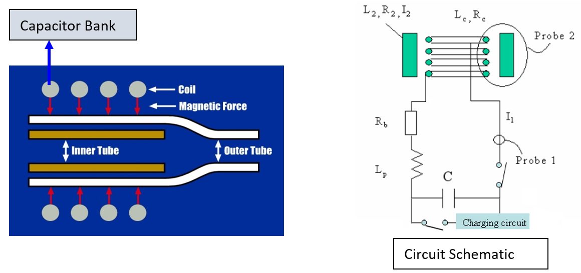
Figure 1: Basic diagram of the MPW process.
The following three elements are fundamental to achieving good magnetic pulse-welded joints:
- Correct welding machine parameters.
- Consideration of metal or material properties.
- Relative positioning of the flyer and the target workpieces.
Welding machine parameters determine the frequency and magnitude of the current waveform. High frequencies typically are favored for MPW. If the frequency is too low, the buildup of eddy currents in the flier workpiece will not be sufficient to achieve the velocities necessary for impact joining. The frequency is directly related to the electrical characteristics (LRC) of the circuit, including the capacitors and coil. Low system capacitances and inductances favor HF characteristics.
The properties of the workpiece metal, particularly of the flier, also contribute to determining the weldability of a given metal. Properties to be considered include electrical conductivity and strength. Metals with high electrical conductivity and low strength are most easily welded with the magnetic pulse process. Higher electrical conductivity facilitates greater induced currents in the flier workpiece, with correspondingly greater magnetic pressures. Lower YS facilitate displacements of the flier at lower magnetic pressures and are easier to accelerate to the required speed for welding. Carbon steel also can be welded when adjustments are made to the system power and frequency. Metals with relatively low electrical conductivity, such as austenitic stainless steels, are almost impossible to directly weld with the magnetic pulse process. They are readily welded, however, with the use of a driver plate. The driver plate is essentially a band of conductive material (typically Cu) wrapped around the low-conductivity flier. During welding, the driver reacts with the coil, pushing the actual flier to the necessary velocities for metallic bonding.A-11
Power Source
The essential component of an MPW system is a capacitor bank. The energy stored in the system can be determined from the size (capacitance) of the bank and the charge voltage using the following equation:
where:
E = Energy
C = Capacitance
V = Voltage
The energy is provided to the capacitors by a dedicated charging system. The capacity of the charging system largely controls the time required to charge the bank between subsequent welds. The charging circuit generally is actively cooled, allowing repeated use during production applications.
As previously mentioned, energy is transferred from the capacitors to the coil with an assembly of bus bars. Two considerations are key in the design of the bus bar assembly: it must have low inductance (in general, the majority of the system inductance should be at the coil), and low resistance contacts. When in use, the capacitors are charged relatively slowly to a predefined voltage. Once this voltage is reached, a fast-action switch is used to allow current flow to the coil. Switching typically is done using solid-state Silicon-Controlled Rectifiers (SCRs).A-11
Tubular Structures
MPW has great potential for joining tubular structures for automotive and aerospace applications and for fluid-carrying tubes. Examples of MPW tubular applications are shown in Figure 2. The process has several advantages that can significantly reduce manufacturing costs, summarized as follows:
1. HS joints can be produced that are stronger than the BM.
2. Leak-tight welds can be made.
3. High welding speeds, in the millisecond range make the process readily adapted to automation.
4. Dissimilar metals and difficult-to-weld materials, such as 303 stainless steel, can be joined.
5. Cold processing enables immediate handling.
6. Welds are made with no HAZ and minimum distortion.
7. Post-cleaning operations and Post Weld Heat Treatments (PWHT) are unnecessary.
8. The process is cost efficient because no filler metals or shielding gases are needed, and environmental costs are reduced.
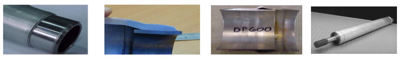
Figure 2: Examples of MPW tubular applications.
Applications
MPW has been successfully applied to various similar and dissimilar metal combinations. Materials with high conductivity, such as Al and Cu, are the easiest to weld with the magnetic pulse process. Al has been successfully welded to steel and stainless steel. Cu has been successfully welded to steel and stainless steel.
MPW has been used to join fuel pipes, fuel filters, exhaust system components, power cables, and for the construction of automotive body parts. The development of new applications of the MPW process continues, with the goal of advancing these applications to mass production. The process is achieving increased recognition for applications across the industrial spectrum.A-11
Safe Practices
The potential hazards of MPW include mechanical and electrical risks, noise, flash, and fumes.
Mechanical
The welding machine should be equipped with appropriate safety devices to prevent injury to the operator’s hands or other parts of the body. Initiating devices, such as push buttons or foot switches, should be arranged and guarded to prevent inadvertent actuation.
Machine guards, fixtures, and operating controls must prevent the operator from coming in contact with the coil and workpiece and must block or deflect the weld jet associated with the process.
Electrical
All doors and access panels on machines and controls must be kept locked or interlocked to prevent access by unauthorized personnel. The interlocks should interrupt the power and discharge all the capacitors through a suitable resistive load when the panel door is open.
Personal Protection
Appropriate guards should be in place to isolate the operator from the process. Operating personnel should wear ear protection when the welding operations produce high noise levels.
Additional information on safe practices for welding is provided in the latest edition of ANSI Safety in Welding, Cutting, and Allied Processes, Z49.1 published by AWS.