Modern car bodies today are made of increasing volumes of Advanced High-Strength Steels (AHSS), the superb performance of which facilitates lightweighting concepts (see Figure 1). To join the different parts of a car body and create the crash structure, the components are usually welded to achieve a reliable connection. The most prominent welding process in automotive production is resistance spot welding. It is known for its great robustness, and easily applicable in fully automated production lines.
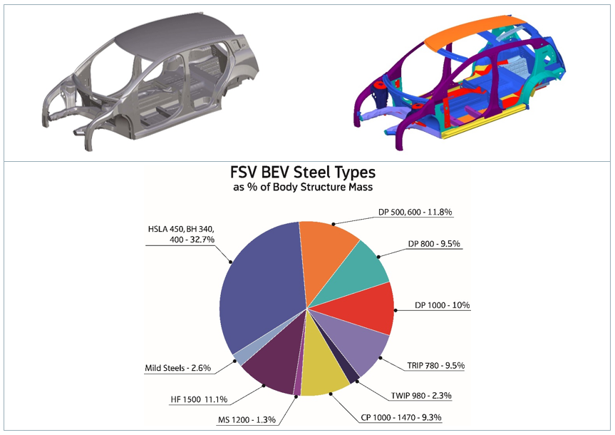
Figure 1: AHSS Content in Modern Car Body.W-7
There are, however, challenges to be met to guarantee a high-quality joint when the boundary conditions change, for example, when new material grades are introduced. Interaction of a liquefied zinc coating and a steel substrate can lead to small surface cracks during resistance spot welding of current AHSS, as shown in Figure 2. This so-called liquid metal embrittlement (LME) cracking is mainly governed by grain boundary penetration with zinc, and tensile stresses. The latter may be induced by various sources during the manufacturing process, especially under ‘rough’ industrial conditions. But currently, there is a lack of knowledge, regarding what is ‘rough’, and what conditions may still be tolerable.
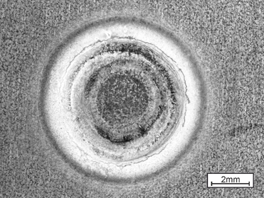
Figure 2: Top View of LME-Afflicted Spot Weld.
The material-specific amount of tensile stresses necessary for LME enforcement can be determined by the experimental procedure ‘welding under external load’. The idea of this method, which is commonly used for comparing cracking susceptibilities of different materials to each other, is to apply increasing levels of tensile stresses to a sample during the welding process and monitor the reaction. Figure 3 shows the corresponding experimental setup.

Figure 3: Welding under external load setup.L-51
However, the known externally applied stresses are not exclusively responsible for LME, but also the welding process itself, which puts both thermally and mechanically induced stresses/strains on the sample. Here, the conventional measuring techniques fail. A numerical reproduction of the experiment grants access to the temperature, stress and strain fields present during the procedure, providing insights on the formation of LME. The electro-thermomechanical simulation model is described in detail in Modelling RSW of AHSS. It is used to simulate the welding under external load procedure (see Figure 4).
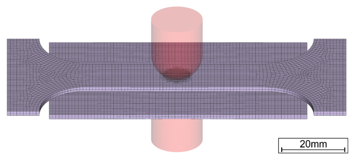
Figure 4: Simulation Model of Welding Under External Load.
The videos that can be found in the link above show the corresponding temperature and plastic strain fields. As heat dissipates quickly through the water-cooled electrode, a temperature gradient towards the adjacent areas and a local temperature maximum on the surface forms. The plastic strains accumulate mainly at the electrode indentation area. The simulated strain field shows a local maximum of plastic deformation at the left edge of the electrode indentation, amplified by the externally applied stresses and the boundary conditions implied by the procedure. This area correlates with experimentally observed LME cracking sites and paths as shown in Figure 5.
The simulation shows that significant plastic strains are present during welding. When external stresses (in reality e.g. due to poor part fit-up or distorted parts) contribute to the already high load, LME cracking becomes more likely. The numerical simulation model facilitates the determination of material-specific safety limits regarding LME cracking. Parameter variations and their effects on the LME susceptibility can easily be investigated by use of the model, enabling the user to develop strict processing protocols to reduce the likelihood of LME. Finally, these experimental procedures can be adapted to other high-strength materials, to aid their application understanding and industrial set-up conditions.
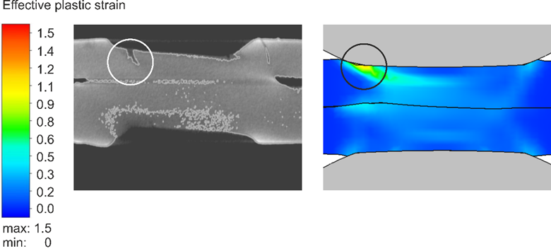
Figure 5: LME Cracks in Cross Section View at Highly Strained Locations.
For more information on this topic, see the paper, co-authored by Fraunhofer and LWF Paderborn, documented in Citation F-23. You may also download the full report documenting the WorldAutoSteel LME project for which this work was conducted.
 |
Dr.-Ing Max Biegler, Group Lead, Joining & Coating Technology Fraunhofer Institute for Production Systems and Design Technology IPK |