This article is a summary of the paper entitled, “IMPROVEMENT OF DELAYED CRACKING IN LASER WELD OF AHSS AND 980GEN3 STEELS”, by Linlin Jiang, Kyle Kram, and Chonghua Jiang.L-62
Researchers from AET Integration, Inc. worked on developing welding techniques that mitigated delayed cracking issues when laser welding Advanced High-Strength Steels (AHSS) and 3rd Gen AHSS. Stitch welds are most likely to have delayed cracking issues therefore the test specimen were cross tension samples with stitch welds. The test was run with ten specimens for each material with the same parameters. The specimen were visually inspected after welding in intervals from 30 min to 12 hours for 48 hours. The specimen were then inspected using X-ray analysis, cross-sectioning, and scanning electron microscope (SEM) analysis. Cracks were observed in the weld schedules used in Figure 1 and 2, and no cracking was observed in the welding schedules developed by researchers as seen in Figure 3 and 4 by altering parameters such as laser power, travel speed, beam oscillation, and defocusing techniques. The techniques are currently patent-pending and were not discussed in the research paper. Further validation tests on 3rd Gen steels is expected in the future.
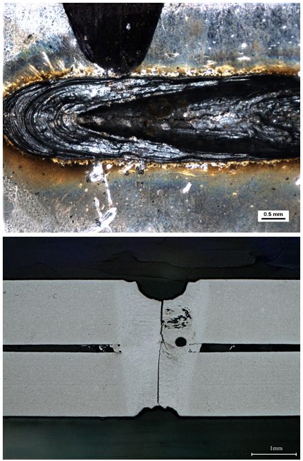
Figure 1: Delayed Crack in Weld of Material A. (Top) Crack from top surface, (Bottom) Cross Section of Crack.L-62
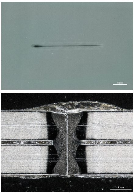
Figure 6: Delayed Cracking in Weld of Material B, (Top) X-ray, (Bottom) Cross section of crack.L-62
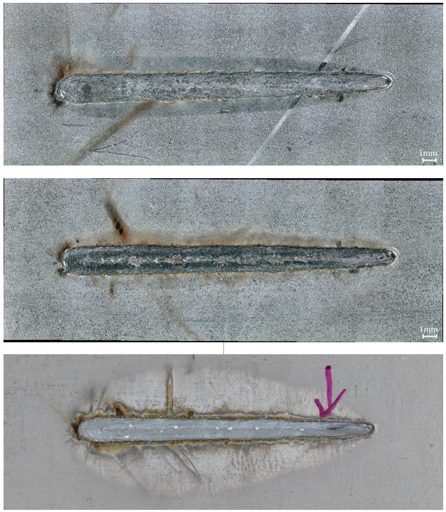
Figure 3: Examples of Visual Inspection Photographs. (Top) Top surface, Material A, (Middle) Top surface, Material B, (Bottom) Top surface, Material C.L-62
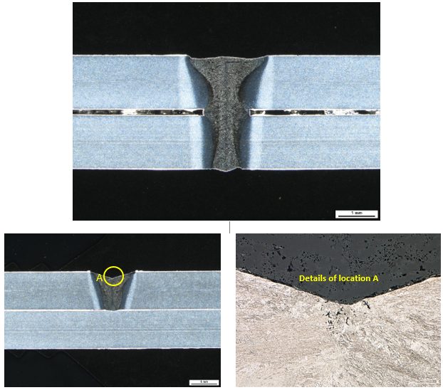
Figure 4: Examples of Cross Section Photographs. (Top) Cross section of weld center, Material A; (Bottom) Cross section of weld crater, Material A.L-62