Blog, homepage-featured-top, main-blog, News
This month’s blog was contributed by Peter Ulintz, Precision Metalforming Association. This content originally appeared in the September 2023 issue of MetalForming Magazine under the title “Stronger AHSS Knowledge Required for Metal Stampers” and has been reproduced with the permission of MetalForming Magazine.
Metal stampers and die shops experienced with mild and HSLA steels often have problems making parts from AHSS grades. The higher initial yield strengths and increased work hardening of these steels can require as much as four times the working loads of mild steel. Some AHSS grades also have hardness levels approaching the dies used to form them.
Dies Get Tougher
Metal stampers and die shops experienced with mild and HSLA steels often have problems making parts from AHSS grades. The higher initial yield strengths and increased work hardening of these steels can require as much as four times the working loads of mild steel. Some AHSS grades also have hardness levels approaching the dies used to form them.
The higher stresses required to penetrate higher-strength materials require increased punch-to-die clearances compared to mild steels and HSLA grades. Why? This clearance acts as leverage to bend and break the slug out of the sheet metal. Stronger materials need longer levers to bend the slug. The required clearance is a function of the steel grade and tensile strength, and sheet thickness.
Increasing cutting clearance can result in punch cracking and head breakage due to higher snapthrough loads and reverse-unloading forces within the die. Adding shear angles to the punch face helps reduce punch forces and reverse unloading.
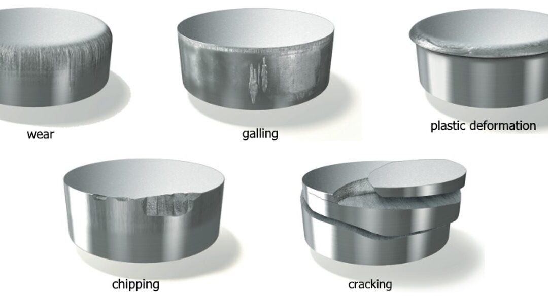
Tight-cutting clearances increase the tendency for die galling and chipping. The severity of galling depends on the surface finish and microstructure of both the tool steel and work material. Chipping can occur when process stresses are high enough to cause low-cycle fatigue of the tooling material, indicating that the material lacks toughness.
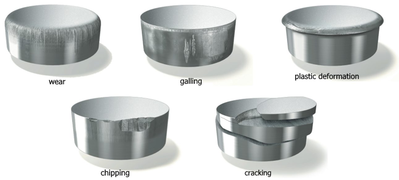
Stamping Tool Failure Modes (Citations T-20 and U-7)
Tempering of tools and dies represents a critical heat-treatment step and serves more than one purpose, but of primary concern is the need to relieve residual stresses and impart toughness. Dies placed in service without proper tempering likely will experience early failure.
Dies made from the higher-alloy tool-steel grades (D, M or T grades) require more than one tempering step. These grades contain large amounts of retained austenite and untempered martensite after the first tempering step and require at least one more temper to relieve internal stresses, and sometimes a third temper for even greater toughness.
Unfortunately, heat treatment remains a “black-box” process for most die shops and manufacturing companies, which send soft die details to the local heat treat facility, with hardened details returned. A cursory Rockwell hardness test may be conducted at the die shop when the parts return. If they meet hardness requirements, the parts usually are accepted, regardless of how they may have been processed—a problem, as hardness alone does not adequately measure impact toughness.
Machines Get Stronger
The increased forces needed to form, cut and trim higher-strength steels create significant challenges for pressroom equipment and tooling. These include excessive tooling deflections, damaging tipping-moments, and amplified vibrations and snapthrough forces that can shock and break dies—and sometimes presses. Stamping AHSS materials can affect the size, strength, power and overall configuration of every major piece of the press line, including material-handling equipment, coil straighteners, feed systems and presses.
Here is what every stamper should know about higher-strength materials:
- Because higher-strength steels require more stress to deform, additional servo motor power and torque capability may be needed to pull the coil material through the straightener. Additional back tension between the coil feed and straightening equipment also may be required due to the higher yield strength of the material in the loop as the material tries to push back against the straightener and feed system.
- Higher-strength materials, due to their greater yield strengths, have a greater tendency to retain coil set. This requires greater horsepower to straighten the material to an acceptable level of flatness. Straightening higher-strength coils requires larger-diameter rolls and wider roll spacing in order to work the stronger material more effectively. But increasing roll diameter and center distances on straighteners to accommodate higher-strength steels limits the range of materials that can effectively be straightened. A straightener capable of processing 600-mm-wide coils to 10 mm thick in mild steel may still straighten 1.5-mm-thick material successfully. But a straightener sized to run the same width and thickness of DP steel might only be capable of straightening 2.5 mm or 3.0-mm thick mild steel. This limitation is primarily due to the larger rolls and broadly spaced centers necessary to run AHSS materials. The larger rolls, journals and broader center distances safeguard the straightener from potential damage caused by the higher stresses.
- Because higher-strength materials require greater stress to blank and punch as compared to HSLA or mild steel, they generate proportionally increased snapthrough and reverse-unloading forces. High-tensile snapthrough forces introduce large downward accelerations to the upper die half. These forces work to separate the upper die from the bottom of the ram on every stroke. Insufficient die-clamping force could cause the upper-die half to separate from the bottom of the ram on each stroke, causing fatigue to the upper-die mounting fasteners.
- Because energy is expended with each stroke of the press—and this energy must be replaced—critical attention must focus on the size (horsepower) of the main drive motor and the rotational speed of the flywheel in higher-strength-steel applications. The main motor, with its electrical connection, provides the only source of energy for the press and it must generate sufficient power to meet the demands of the stamping operation. The motor must be properly sized to replace the increased energy expended during each press stroke. For these reasons, some stampers consider the benefits of servo-driven presses for these applications.
As steels becomes stronger, a corresponding increase in process knowledge is required in terms of die design, construction and maintenance, and equipment selection.
You can read more about these topics at these links:
Tooling and Die Wear
Coil Processing Straightening and Leveling
Press Requirements

Thanks go to Peter Ulintz, of the Precision Metalforming Association (PMA) for authoring this article. Ulintz was employed in the metal stamping and tool & die industries for 38 years before joining Precision Metalforming Association (PMA) in 2015. He provides industry-related training and seminars in Stamping Press Operation and Setup; Designing and Building Metal Stamping Dies; Die Maintenance and Troubleshooting; Metal Stamping Design for Manufacturability; Deep Draw Tooling and Process Technology; Stamping Higher Strength Steels; and Problem Solving in the Press Shop. Peter is a contributor to ASM Handbook, Volume 14B, Metalworking: Sheet Forming (2006) and writes the monthly column, Tooling by Design, for PMA’s monthly publication, MetalForming Magazine.
![Forming and Formability of AHSS]()
Forming
Introduction
Approaches for forming higher strength steels evolved with the commercialization of increased strength levels of High Strength Low Alloy (HSLA) steels. Demands for greater crash performance while simultaneously reducing mass and cost have spawned the development of new groups of steels that improve on the properties of these HSLA steels. Forming of Advanced High-Strength Steel (AHSS) is not a radical change from forming conventional HSLA steels, providing some of the key differences are understood and accounted for in die design, die process, and equipment selection.
AHSS grades solve two distinct automotive needs by two different groups of steels. The first group as a class has higher strength levels with improved formability and crash-energy absorption compared to HSLA grades. DP, TRIP, FB, and TWIP steels, which have increased values of the work hardening exponent (n-value), fulfill this requirement. The second group, including CP and MS steels, extends the availability of steel in strength ranges above what is available with HSLA grades. Originally targeted for chassis, suspension, and body-in-white components, AHSS grades are now being applied to doors and other body panels. New variations in microstructure help meet specific process requirements, including increased edge stretch, bendability, strengthening after forming, or tighter property tolerances.
The progressive increases in yield and tensile strength with these new AHSS grades magnifies existing forming issues with conventional HSLA grades and creates new challenges. Concerns include higher loads on processing equipment including presses, levelers, straighteners, blanking lines, coil slitting lines and roll forming equipment. Additionally, there are material and surface treatment considerations required for tooling in the stamping plants: draw dies, trim steels, and flange steels. Compared to conventional HSLA steels, greater energy requirements result from higher AHSS yield strengths, tensile strengths and significantly higher work hardening rates. This places new requirements on press capacity, leveler, straightener and slitting capabilities, tool construction/protection, lubricant capabilities, part and process design, and maintenance. Springback management becomes more critical as yield strengths continue to increase. Conventional and press hardened (hot formed) AHSS parts have very high strength after forming, so re- forming operations should be avoided. Trimming, cutting, and piercing equipment must be constructed and maintained to overcome the extreme high strength of the final stamping. Laser cutting of press hardened parts produces a finished part that avoids pushing the limits of trim and pierce tools and dies utilized for conventional HSLA steel.
There are an ever-increasing number of AHSS multiphase microstructure grades available, each designed to resist various forming failure modes while achieving final part performance requirements. Sharing of information regarding the planned part geometry, die and stamping processing, and final part application between steel suppliers, product and die process engineering, and end users helps ensure selection of the right steel grade for the application. This becomes especially relevant since multiphase microstructures experience additional forming failure modes compared with conventional high strength products.
Tool Design Considerations
The characteristics associated with different AHSS grades influence die design and die processing decisions. Not only are these steels typically higher in strength, but they also undergo substantial work hardening during forming. These lead to increased local loads, and changes in friction, die wear, and press requirements. The multiphase microstructures increase cut edge and bending fracture sensitivity. As such, extending the life and performance of tooling in press shops requires a rethinking of tool and part design.
Part Design
Successful application of any material requires close coordination of part design and the manufacturing process. Consult product and manufacturing process engineers when designing AHSS parts to understand both the limitations and advantages of the grade and the proper forming process to be employed. Start in the concept and feasibility stage to ensure sufficient time for corrective actions and optimization.
Soft tool materials like kirksite may be used for manufacturing prototype parts and the inserts used to eliminate local wrinkles or buckles. However, wear resistant coatings are typically not applied to these tool surfaces, so the metal flow seen in these prototype parts may not match the metal flow seen under production conditions. The results from soft tool tryouts should not be used to assess manufacturability and springback of AHSS parts.
Design structural frames (such as rails, sills, cross members, and roof bows) as open-ended channels to permit forming operations rather than draw die processes. AHSS stampings requiring closed-end draw operations are limited by a reduced depth of draw, Figure 1. Less complex, open-ended stamped channels are less limited in depth. A rule of thumb is that DP 350Y600T can be formed to only half the draw depth of a mild steel.

Figure 1: Schematic of an open end part design (left) and a closed end part design (right). The open-ended design allows for greater depths when utilizing AHSS versus the closed ended design historically used with mild steel.A-5
Where possible, avoid closed-end developments to make more complex geometries with AHSS grades. Wrapping ends of “hat” sections increases forming loads, increases the chances of circumferential compression wrinkling on the binder, specifically in the corners, and increases wrinkling on the draw wall if the blank edge runs through the draw bead. Draw die developments that include a closed (or wrapped) end development usually also require a larger blank size. During draw die development, it is best to identify parts that have a “hat” section geometry in certain locations and develop the draw die accordingly to maximize the positive formability attributes of AHSS while minimizing the limitations of AHSS.
For example, the left image in Figure 2 shows a draw die development on a DP600 cowl side with a closed (wrapped) end, with the right image showing a similar part developed with an open end. Although both final part geometries are similar, the closed-end development led to significant global formability failures due to the excessive stretch. In contrast, the open-ended development had virtually no global formability related failures. Other design and die development differences in the part on the right include the use of stake beads to control springback and embossments to eliminate wavy metal. In addition, an open-ended development has the potential to reduce the blank size for material utilization savings.

Figure 2: Draw die development for a cowl side formed from DP600. Left image: closed-end development with global formability failures, waviness, and springback. Right image: open-ended development with no splits, waves, or dimensional concerns.U-6
The automotive industry has adopted a strategy for “lighter dies and fewer dies”, to reduce cost. One key element is “part consolidation”, such as one-piece body side outers and inners. High strength steels challenge the part consolidation mantra. When encountering extreme formability challenges, parts previously made with one set of dies when stamped from lower strength steels may benefit from transitioning to a laser welded blank with a lower strength grade in the challenging region and higher strength steels in the remainder of the part. Alternatively, splitting the consolidated part into two or more separate parts subsequently welded together may improve stamping success at the expense of another operation. In the past, one-piece rocker panels were stamped from conventional mild or HSLA steel. However, this component requires higher strength and reduced thickness to meet weight and crash requirements, so now DP980 is often considered as the grade of choice for this application. Figure 3 shows a rocker panel where insufficient formability of DP980 prevented a one-piece stamping. The OEM solved this by dividing the part into two stampings, putting a more formable grade where needed on the wrapped (or closed) end.

Figure 3: When a one-piece rocker panel could not be successfully formed from DP980, the OEM stamped a DP980 rocker panel section with an open-ended design and spot welded it to a mild steel end cap.U-6
Trim and Pierce Tool Design
- Trim and pierce tools need to withstand higher loads since AHSS grades have higher tensile strengths than conventional high-strength steels.
- Edge cracking is minimized with proper support of the trim stock during trimming.
- Modify timing of the trim/pierce operation to minimize snap-through reverse loading.
- Scrap shedding may be an issue, since AHSS springback can cause scrap to stick in the tool.
Flange Design
- Design more formable flanges to reduce need for extra re-strike operations.
- Areas to be flanged should have a “break-line” or initial bend radius drawn in the first die to reduce springback.
- Adapt die radii for material strength and blank thickness.
Draw Bead Design
- Metal flow across draw beads generates strain and minimizes the elastic recovery which causes springback.
- Metal flow across draw beads generates large amounts of work hardening, leading to increased press loads.
- Optimizing blank size and shape reduces the reliance on draw beads, which can excessively work harden the material before entering the die opening.
Guidelines to Avoid Edge Cracking During Stretch Flanging
- Flange length transition should be gradual – abrupt changes in flange length cause local stress raisers leading to edge cracks.
- Use good cutting practices to achieve a high-quality edge.
- Avoid the use of sharp notch features in curved flanges.
- Avoid putting bypass notches in stretch or compression edges of blanks or progressive die carrier strips. These bypass notches can act as stress risers and lead to edge fractures in the draw or flange operation. In addition, bypass notches in blanks and progressive dies are difficult to maintain, which can increase the potential for edge fracture.
- Metal gainers in the draw die or in the die prior to the stretch flange operation compensates for change in length of line that occurs during flanging, helping to avoid edge cracking. In the example shown in Figure 4, edge fractures moved from the draw panel to flanged panel after grinding on the draw die to eliminate edge fractures in the draw operation. The draw panel underneath the flanged part in Figure 4 did not have edge fractures. The reduction in the length of line in the draw operation moved the problem to the flanged part where the stamping transitioned from bending and straightening in the flange operation to a stretch flange operation. A better practice is to add metal gainers to the draw panel to provide the feedstock which expands during stretch flanging.

Figure 4: Flanged panel fractures, with the draw panel underneath. Adding metal gainers to the draw panel would help minimize these fractures.U-6
- The higher strength of AHSS makes it more difficult to pull out loose metal or achieve a minimum stretch in flat sections of stampings. Addendum, metal gainers (Figures 5 and 6), and other tool features balance lengths of line and locally increase stretch.

Figure 5: Metal gainers help avoid insufficient stretched areas and eliminate buckles.T-3

Figure 6: Metal gainers and depressions balance stresses and minimizes wrinkled metal.A-41
Coil Processing
Steel production and processing are continuous operations where the last step is coiling. Steelmakers and processors use tension when coiling to avoid producing “soft” or collapsing coils. Coiling induces tensile and compressive stresses into the strip, and these stresses can contribute to blank or part distortion in subsequent processes. Unless sufficient winding tension adjustments are made, the degree of these stresses change throughout the coil – whereas the outer laps of the coil may be on the order of 6 feet (1800 mm) in diameter, the inner laps typically are wound on a 20 inch to 24 inch (500 mm to 600 mm) diameter mandrel. In addition, the magnitude of these stresses increases with higher strength products, leading to coil shape imperfections like coil set and crossbow.
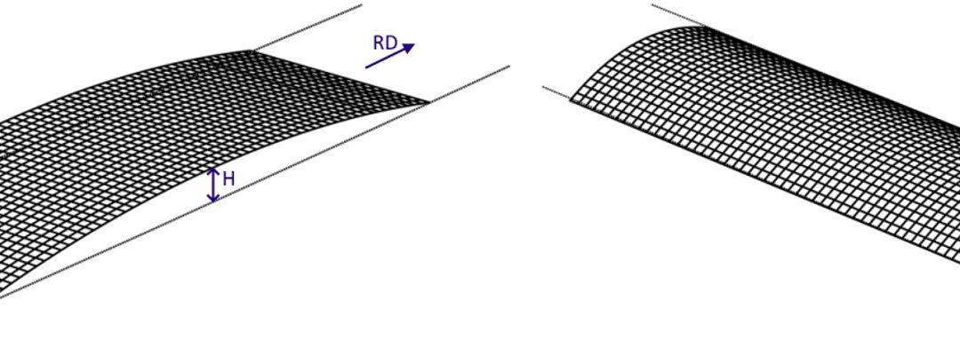
Coil set is a bow condition parallel with the rolling direction, and curves downward in the same direction as the upper outside lap of an overwound coil (Figure 1a). Here, the top surface of the coil or strip is stretched more than the bottom surface, and typically becomes more severe as the coil is processed and the lap diameter decreases. Crossbow is a bow condition perpendicular to the rolling direction, and curves downward in the same direction as the upper outside lap of an overwound coil, with the center portion of the sheet raised a measurable amount above the sheet edges (Figure 1b).
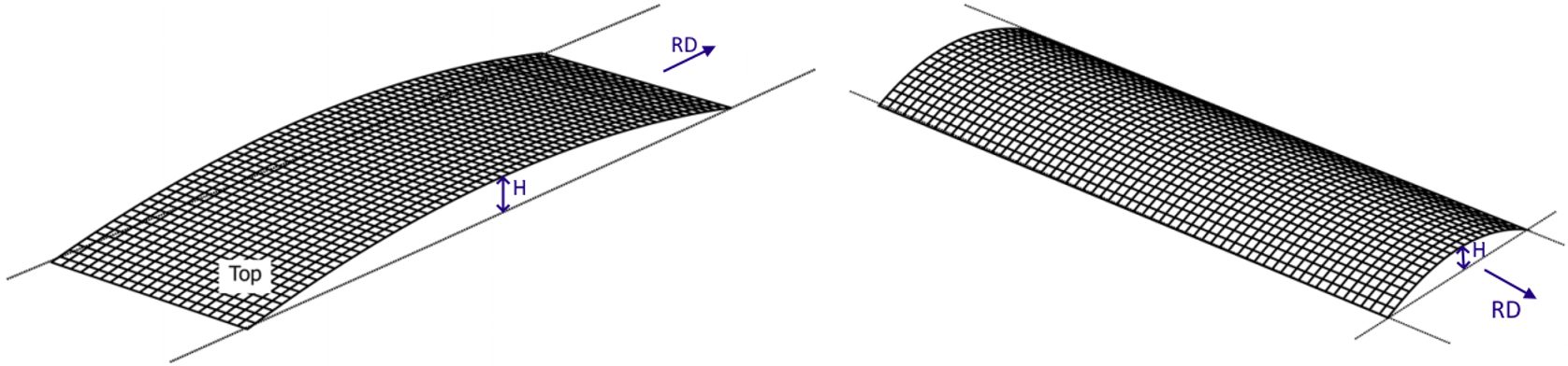
Figure 1: Coil shape imperfections – A) Coil set and B) CrossbowA-30
The first operation when unwinding a coil is some type of shape correction to ensure flatness before further processing. There are two main types of equipment used to create a flat coil – a straightener and a precision leveler. While these two types of equipment are similar, a precision leveler has additional capabilities. Both bend the coil back and forth over a series of work rolls to alternately stretch and compress the upper and lower surfaces (Figure 2). Critical equipment parameters include roll diameter, roll spacing, backup rolls, roll material type, gear design, backup rolls, overall system rigidity, and power requirements. The amount of force required to relieve the residual stresses is a function of the sheet thickness and yield strength. Equipment sufficient for shape correction on conventional grades may not be sufficient to completely flatten the advanced steel grades available now and in the future.
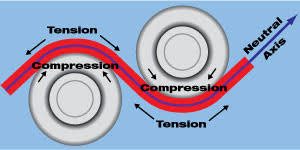
Figure 2: Alternately stretching and compressing the upper and lower sheet surfaces by passing the coil through work rolls.C-8
Straighteners and levelers have a series of rolls that progressively flex the strip to remove the residual stresses. Each successive roll pair has an adjustable gap to deform the sheet to a targeted amount with the goal of resulting in a flat coil once the steel passes through all the rolls. The entry end has the smallest gap, putting in the most deformation. The last pair of rolls has the largest gap, usually set for metal thickness. The gap profile varies based on thickness, yield strength, and equipment (Figure 3). Many equipment manufacturers have generated tables to guide the operator as to the best settings for various yield strength/thickness combinations.
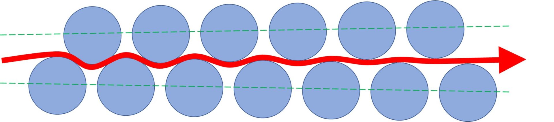
Figure 3: The severity of the bending and unbending around the work changes with the roll gap, roll diameter, and roll spacing.
Removing coil set requires permanent yielding in the outer 20 percent of the top and bottom surfaces of the metal. The central 80 percent of the thickness remains unchanged.T-14 Straighteners are appropriate for this type of shape correction (Figure 4). Only end bearings support the simplest straighteners, with no backup rolls used. Closing the entry roll gap risks deflection of the unsupported center, potentially leading to creating edge waves in the coil.
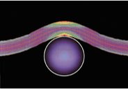
Figure 4: Computer generated analysis showing a straightener roll working the outer 20% of the steel strip. The different colors indicate the bending force, which is symmetrical the neutral fiber (the center part that is neither compressed nor stretched). Red areas indicate stresses beyond the yield point, and yellow areas indicate material is at the yield point. Other areas are in the elastic range.T-15
Eliminating crossbow and other shape imperfections like buckles or waves requires permanent yielding in the outer 80 percent of the top and bottom surfaces, with only the central core — 20 percent — remaining in the elastic range.T-14 Precision levelers, which applies tension to the strip as it bends around more smaller diameter rolls, can achieve this deformation (Figure 5). While this deformation can get the coil shape closer to flat, it also reduces the inherent formability of the grade. Processors should use only the least amount of deformation necessary to correct the shape to retain sufficient formability for stamping or other operations.
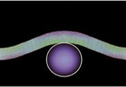
Figure 5: Computer generated analysis showing a leveler roll working the outer 80% of the steel strip while it is under tension. The stress pattern is not symmetrical, with higher stresses seen on the outside of each bend. Passing through the multiple small-diameter rolls under tension results in stresses exceeding the yield point through most or all of the cross section.T-15
Yield point elongation (YPE), Lüders lines, and stretcher strains are names describing the same phenomenon seen in some annealed or aged metals. A related defect called fluting occurs in V-bending. Leveling at-risk coils with repeated cycles of bending and unbending, like shown in Figure 3, may be an effective way to minimize stretcher strains or fluting. However, process control is critical, since excessive leveling work hardens the coil and results in increased strength and reduced ductility. On the other hand, insufficient leveling does not address the defects related to the yield-point phenomenon.
Recent studies K-24, K-48, K-49 describe the importance of sufficient leveling, using real-world examples as well as simulation to model the phenomena and show potential corrective actions, as shown in the following animations.K-50
Figure 6 shows an animation of V-bending without any roller leveling. The fluting defect occurs, since the formed panel shape does not conform to the punch. Figure 7 is an animation of leveling with roller penetration deep enough to produce deformation equivalent to an 85% plastic fraction. Figure 8 presents a closer view of the V-bending, highlighting improved formed panel shape conformance to the punch. The references cited above detail the simulation methodology.
Figure 6: V-bending without roller leveling leads to fluting.K-50
Figure 7: Leveling to produce 85% plastic fraction.K-50
Figure 8: V-bending after leveling to produce 85% plastic fraction minimizes the fluting defect.K-50
Design and Processing Implications
The progressively higher yield strengths for AHSS are challenging the capabilities of straighteners and precision levelers that were not designed for flattening these high strength materials. Equipment manufacturers have been studying and developing solutions to address this issue. There are a series of factors related to the design of straighteners and precision levelers affected by advanced steel grades:
Roll Diameter – Leveling rolls for AHSS generally are smaller in diameter than those used for mild steel, providing a smaller radius around which to bend the material. This is because exceeding the higher yield strength of Advanced High Strength Steels requires a more aggressive bend.
Roll Spacing – Work roll center-spacing will be closer for AHSS than for comparable mild steels. Closer spacing leads to the requirement of more force to reverse-bend the material, resulting in greater power requirements for processing.
Roll Support – Larger journal diameters with larger radii and bearing capacity will withstand the greater forces and higher power required to straighten AHSS.
Roll Depth Penetration – The upper rolls must have enough travel to be able to penetrate the lower fixed rolls sufficiently so the deformation exceeds the yield strength of the AHSS grade. This penetration may need to be as much as 50 to 60 percent greater than for mild steels.
Roll Deflection – Given the greater force requirements for straightening AHSS, work roll deflection becomes a concern especially with smaller-diameter rolls more likely to flex and deflect. Processing wider sheet also increases the deflection risk. Excessive work roll deflection results in undesirable side effects such as edge waves, increased journal stresses and premature gear failure. Backup rollers prevent excessive work roll deflection.
Roll Material – Higher strength materials and special heat treatment should be employed to ensure rolls can withstand greater stresses for longer periods without experiencing fatigue failure.
Gear Materials – Gears that drive the rolls should be produced from heat treated high strength materials to produce smooth running, chatter free roll drive for long life under high loads.
Gear Positioning – Closer roll center spacing requires higher power transmission and results in a smaller gear-pitch ratio, which reduces gear power ratings.
Gear Sizes – To compensate for the gear positioning issue, flattening AHSS grades requires wider gear faces as well as stronger outboard support of journals and idler shafts to produce higher gear power ratings.
Frame Rigidity – The higher strength of advanced steels results in stresses throughout all the components of the processing unit. Frame rigidity is vital to prevent work roll deflection.
Equipment manufacturers have also developed design solutions that address processing of AHSS. As an example, several manufacturers have designed equipment with removable cartridges allowing for swapping between sets containing differently sized rolls, gears, and support structures. As they switch jobs from AHSS to conventional steels, they swap in the appropriate cartridge. This also allows for off-line roll cleaning and maintenance.
Remember that the likelihood of coil set and residual stresses in the coil increases with strength. Operators must take proper precautions when cutting the strapping banks used in coil shipment to avoid “clock-springing.”
Newer processing equipment may contain additional hold-down arms or other features to protect both plant personnel and equipment from damage.E-11
Material Handling Considerations When Working With Higher Strength Steels (U-13)
Stamping AHSS materials can affect the size, strength, power and overall configuration of every major piece of the press line, including material-handling equipment, coil straighteners, feed systems and presses.
Higher-strength materials, due to their greater yield strengths, have a greater tendency to retain coil set. This requires greater horsepower to straighten the material to an acceptable level of flatness. Straightening higher-strength coils requires larger-diameter rolls and wider roll spacing in order to work the stronger material more effectively. But increasing roll diameter and center distances on straighteners to accommodate higher-strength steels limits the range of materials that can effectively be straightened. A straightener capable of processing 600-mm-wide coils to 10 mm thick in mild steel may still straighten 1.5-mm-thick material successfully. But a straightener sized to run the same width and thickness of DP steel might only be capable of straightening 2.5 mm or 3.0-mm thick mild steel. This limitation is primarily due to the larger rolls and broadly spaced centers necessary to run AHSS materials. The larger rolls, journals and broader center distances safeguard the straightener from potential damage caused by the higher stresses.