- Fundamentals and Principles of HF Welding
- Advantages and Disadvantages
- Induction Seam Welding of Pipe and Tubing
- Contact Seam Welding of Pipe and Tubing
Fundamentals and Principles of HF Welding
High Frequency (HF) welding processes rely on the properties of HF electricity and thermal conduction, which determine the distribution of heat in the workpieces. HF contact welding and high-frequency induction welding are used to weld products made from coil, flat, or tubular stock with a constant joint symmetry throughout the length of the weld. Figure 1 illustrates basic joint designs used in HF welding. Figures 1 (A) and (B) are butt seam welds; Figure 1 (C) is a mash seam weld produced with a mandrel, or backside/inside bar. Figure 1 (D) is a butt joint design in strip metal; and Figure 1 (E) shows a T-joint. Figures 1 (F) and (G) are examples of helical pipe and spiral-fin tube joint designs. Figure 1 (J) illustrates a butt illustrates a butt joint in pipe, showing the placement of the coil. Figure 4.L-6 (K) shows a butt joint in bar stock.
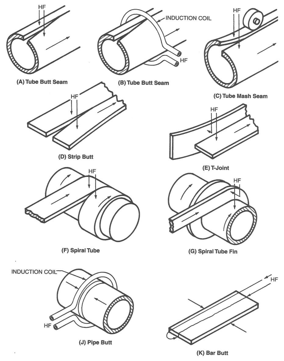
Figure 1: Basic joint designs for HF welds in pipe, tube, sheet, and bar stock.
HF current in metal conductors tends to flow at the surface of the metal at a relatively shallow depth, which becomes shallower as the electrical frequency of the power source is increased. This commonly is called the skin effect. The depth of electrical current penetration into the surface of the conductor also is a function of electrical resistivity, and magnetic permeability, the values of which depend on temperature. Thus, the depth of penetration also is a function of the temperature of the material. In most metals, the electrical resistivity increases with temperature; as the temperature of the weld area increases, so does the depth of penetration. For example, the resistivity of low-carbon steel increases by a factor of five between room temperature to welding temperature. Metals that are magnetic at room temperature lose the magnetic properties above the Curie temperature. When this happens, the depth of penetration increases drastically in the portion of metal that is above the Curie temperature while remaining much shallower in the metal that is below the Curie temperature. When these effects are combined in steel heated at a frequency of 400 kHz, the depth of current penetration is 0.05 mm (0.002 in.) at room temperature, while it is 0.8 mm (0.03 in.) at 800°C (1470°F). The depth of current penetration for several metals as a function of frequency is shown in Figure 2.
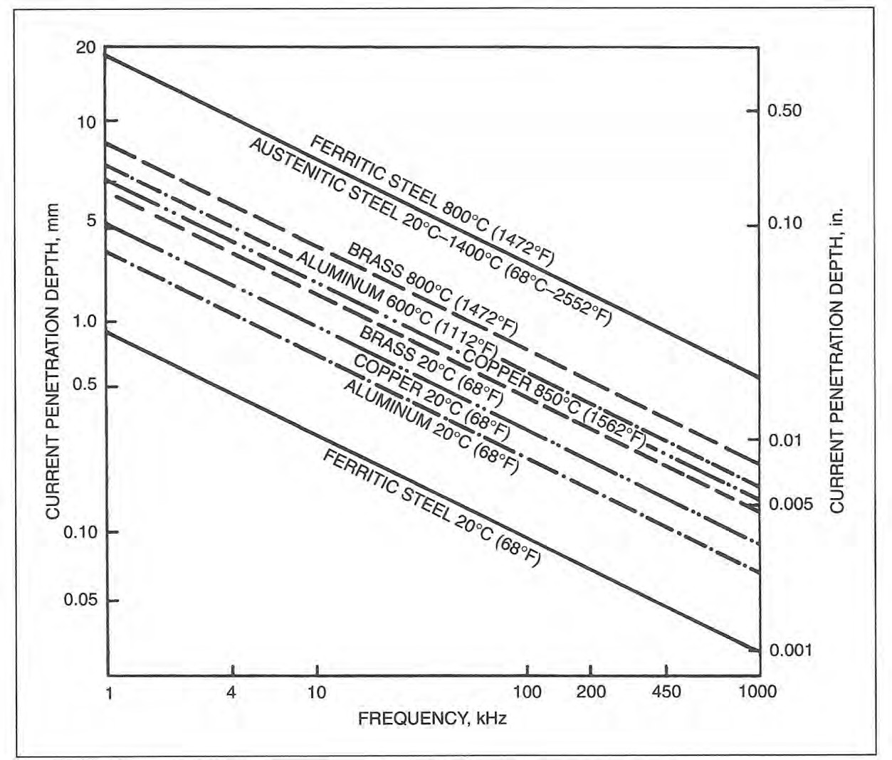
Figure 2: Effect of frequency on depth of penetration into various metals at selected temperatures.
The second important physical effect governing the HF welding process is thermal conduction of the heat generated by the electric currents in the workpiece. Control of the thermal conduction and of the penetration depth provides control of the depth of heating in the metal. Because thermal conduction is a time-dependent process, the depth to which the heat will conduct depends on the welding speed and the length of the electrical current path in the workpiece. If the current path is shortened or the welding speed is increased, the heat generated by the electric current in the workpiece will be more concentrated and intense. However, if the current path is lengthened or the welding speed is reduced, the heat generated by the electric current will be dispersed and less intense. The effect of thermal conduction is especially important when welding metals with high thermal conductivity, such as Cu or Al. It is not possible to weld these materials if the current path is too long or the welding speed is too slow. Changing the electrical frequency of the HF current can compensate for changes in welding speed or the length of the weld path, and the choice of frequency, welding speed, and path length can adapt the shape of the HAZ to optimize the properties of the weld metal for a particular application.A-11, A-15
Advantages/Disadvantages of HF Welding
A wide range of commonly used metals can be welded, including low-carbon and alloy steels, ferritic and austenitic stainless steels, and many Al, Cu, Ti, and Ni alloys.
Because the concentrated HF current heats only a small volume of metal at the weld interface, the process can produce welds at very high welding speeds and with high energy efficiency. HF can be accomplished with a much lower current and less power than is required for low-frequency or direct-current resistance welding. Welds are produced with a very narrow and controllable HAZ and with no superfluous cast structures. This often eliminates the need for Post-Weld Heat Treatment (PWHT).
Oxidation and discoloration of the metal and distortion of the workpiece are minimal. Discoloration may be further reduced by the choice of welding frequency. Maximum speeds normally are limited by mechanical considerations of material handling, forming and cutting. Minimum speeds are limited by material properties, excessive thermal conduction such that the heat dissipates from the weld area before bringing it to sufficient temperature, and weld quality requirements. The high process speed may also become a disadvantage if process settings are incorrect, as scrap can be generated at very high rates.
Considering the high processing speeds, with the high equipment cost required for HF welding, it is important to understand the amount of product needs for economic justification.
The fit-up of the surfaces to be joined and the way they are brought together are important if high-quality welds are to be produced. However, HF welding is far more tolerant in this regard than some other processes.
Flux is almost never used but can be introduced into the weld area in an inert gas stream. Inert gas shielding of the weld area generally is needed only for joining highly reactive metals such as Ti or for certain grades of stainless steel.A-11, A-15
Induction Seam Welding of Pipe and Tubing
The welding of continuous-seam pipe and tubing is the predominant application of HF induction welding. The pipe or tube is formed from metal strip in a continuous-roll forming mill and enters the welding area with the edges to be welded slightly separated. In the weld area, the open edges of the pipe or tube are brought together by a set of forge pressure rolls in a vee shape until the edges touch at the apex of the vee, where the weld is formed. The weld point occurs at the center of the mill forge rolls, which apply the pressure necessary to achieve a forged weld.
An induction coil, typically made of Cu tubing or Cu sheet with attached water- cooling tubes, encircles the tube (the workpiece) at a distance equal to one to two tube diameters ahead of the weld point. This distance, measured from the weld point to the edge of the nearest induction coil, is called the vee length. The induction coil induces a circumferential current in the tube strip that closes by traveling down the edge of the vee through the weld point and back to the portion of the tube under the induction coil. This is illustrated in Figure 3.
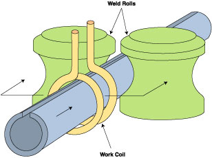
Figure 3: HF induction seam welding of a tube.
The HF current flows along the edge of the weld vee due to the proximity effect (see Fundamentals), and the edges are resistance-heated to a shallow depth due to the skin effect.
The geometry of the weld vee is such that its length usually is between one and one half to two tube diameters long. The included angle of the vee generally is between 3 and 7 degrees. If this angle is too small, arcing between the edges may occur, and it will be difficult to maintain the weld point at a fixed location. If the vee angle is too wide, the proximity effect will be weakened causing dispersed heating of the vee edges, and the edges may tend to buckle. The best vee angle depends on the characteristics of the tooling design and the metal to be welded. Variations in vee length and vee angle will cause variations in weld quality.
The welding speed and power source level are adjusted so that the two edges are at the welding or forge temperature when they reach the weld point. The forge rolls press the hot edges together, applying an upset force to complete the weld. Hot metal containing impurities from the faying surfaces of the joint is squeezed out of the weld in both directions, inside and outside the tube. The upset metal normally is trimmed off flush with the BM on the outside of the tube, and sometimes is trimmed from the inside, depending on the application for the tube being produced.A-11, A-15
Contact Seam Welding of Pipe and Tubing
The HF contact welding process provides another means of welding continuous seams in pipe and tubing. The process essentially is the same as that described above for induction welding and is illustrated in Figure 4. The major difference is that sliding contacts are placed on the tube adjacent to the unwelded edges at the vee length. With the contact process, the vee length generally is shorter than that used with the induction process. This is because the contact tips normally can be placed within the confines of the forge rolls where the induction coil must be placed sufficiently behind the forge rolls, so that the forge rolls are not inductively heated by the magnetic field of the induction coil. Because of the shorter vee lengths achievable with the contact process, an impeder often is not necessary, particularly for large-diameter tubes where the impedance of the current path inside the tube has significant inductive reactance.

Figure 4: Joining a tube seam with HFRW using sliding contacts. Note: Vee length extends from point of welding to sliding contacts.
An impeder, which is made from a magnetic material such as ferrite, generally is required to be placed inside the tube. The impeder is positioned so that it extends about 1.5 to 3 mm (1/16 to 1/8 in.) beyond the apex of the vee and the equivalent of one to two workpiece diameters upstream of the induction coil. The purpose of the impeder is to increase the inductive reactance of the current path around the inside wall of the workpiece. This reduces the current that would otherwise flow around the inside of the tube and cause an unacceptable loss of efficiency. The impeder also decreases the magnetic path length between the induction coil and the tube, further improving the efficiency of power transfer to the weld point. The impeder must be cooled to prevent its temperature from rising above its Curie temperature, where it becomes nonmagnetic. For ferrite, the Curie temperature typically is between 170 and 340°C (340 and 650°F).A-11, A-15