Figure 1 shows a typical cross-section of a resistance spot weld (RSW) joint of 1 mm-thick H220 Zn-coated High-Strength Steel and 1.5 mm-thick 6008-T66 aluminium alloy. Based on resistance spot welding process simulation by ANSYS, the Al/Steel interface temperature is 1120 oC with welding current of 9 kA and welding time of 300 ms. The high interfacial temperature at the Al/Steel interface melts Al alloys and liquid Al alloy wet and spread on the solid steel surface which creates a special brazed joint.
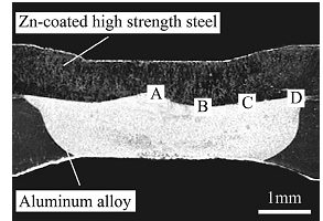
Figure 1: Cross-sectional macrostructure of typical Al/Steel resistance spot welds.Z-4
The interaction of liquid Al alloy with solid steel results in the formation of Fe-Al intermetallics (IMCs), which are mainly composed of lath-like/tongue-like shaped η-Fe2Al5 on steel side and coarse/fine needle-like shaped θ-FeAl3/Fe4Al13 on Al alloy side. For the morphology shown in Figure 2, IMCs have higher hardness compared to the Al or steel base metal, with average hardness of approximately 8.7 and 6.5 GPa for Fe2Al5 and Fe4Al13 respectively, while the average hardness of Al and steel near to the interface were 1.1 and 2.1 GPa respectively.Z-2 The distribution of IMCs at the Al/steel interface is non-uniform, with the thickest IMCs at the center of the weld and a reduced IMCs thickness observed approaching the weld periphery.
The formation and growth of IMCs at the Al/Steel interface are mainly affected by the temperature at the Al/Steel interface and reactive diffusion time. With constant welding current of 9 kA, the thickness of the IMCs increase from 2.9 µm to 13 µm as welding time increases from 100 ms to 300 ms. With constant welding time of 250 ms, a rapid increase of the IMCs from 1.5 to 5.6 µm is observed as welding current increases from 5 to 9 kA. Thus, with increasing welding time and/or welding current, IMCs thickness increase due to the higher interfacial temperature and longer reaction time of liquid Al alloy with solid steel. Resistance spot welding of A6008 andH220 Zn-coated High-Strength Steel can achieve a peak strength of 3.3 kN at welding current of 9 kN and welding time of 250 ms with interfacial fracture at the Al/steel interface, since the crack initiates at the brittle IMC compound layer (Fe2Al5) and tends to propagate along the IMC layer.Z-3
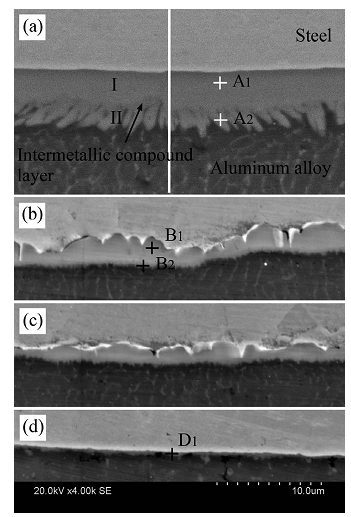
Figure 2: SEM images of Al/Steel interface regions in previous figure. (a)-(d) corresponds to region A-D respectively.Z-4
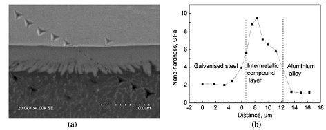
Figure 3: Nanoindentation across H22YD GI high strength steel/A6008-T66 resistance spot weld: (a) Nanoindents; (b) Nanohardness profile.Z-4
The nugget diameter, IMC compound layer thickness and mechanical properties of Al/steel weld joints can be affected by electrode morphology. For resistance spot welding of A6008-T66 and H22YD galvanized High- Strength Steel, the optimized electrodes were a planar circular electrode with a surface diameter of 10 mm on steel side and a spherical tip with a spherical diameter of 70 mm on Al side.Z-4 Compared to the conventional F type electrode used in the reference studyZ-3, a flat Al/steel interface can be obtained with larger nugget diameter and less welding defects, including shrinkage void and cracks, as shown in Figure 4. A maximum nugget size of 10 mm can be obtained with the optimized electrode morphology with a reduced intermetallic compound thickness of 4 µm (Figure 5). A peak tensile shear strength of 5.4 kN can be achieved with a nugget pull-out failure mode (Figure 6).
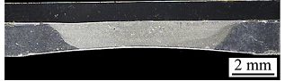
Figure 4: Cross-sectional macrostructure of resistance spot weld Al/steel joint with an electrode spherical diameter of 100 mm on Al alloy side.Z-4
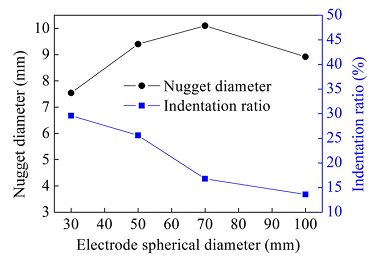
Figure 5: Effects of electrode spherical diameter on nugget diameter and indentation ratio of resistance spot weld joints.Z-4
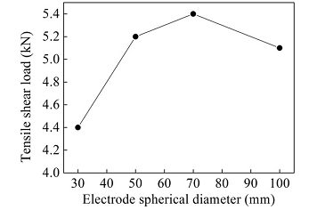
Figure 6: Effects of electrode spherical diameter on tensile shear load of resistance spot weld joints.Z-4
Sigler et al., from General Motors, have shown considerable improvement in the Al/Steel RSW joints that includes multi step direct RSW welding and multi ring, domed-shaped electrodes.S-15, W-14 Welds were carried out using a medium frequency direct current (MFDC) RSW machine via two current pulses, i.e. pre heat pulse of 5 kA and main pulse of 13 kA, 14 kA and 15 kA at various times. Their methodology has shown an importance in the IMC layer thickness and aluminium nugget. Figure 7(a) shows the cross sections of the welds made at the various parameters. More indentation and larger Al nugget diameter are seen at higher times. Figure 7(b) shows that the hardness mapping and the softened region on the both sides of the nugget is observed due to excessive recrystallization. Figure 7(c) shows that the greater the aluminium nugget diameter in the center, the less is the aluminium thickness in the center. Also the IMC layer, as shown in Figure 12(d) increases with the longer weld times. Overall, it was found that the larger aluminium nugget diameter and thicker IMC layer is detrimental for Al/Steel joint integrity.
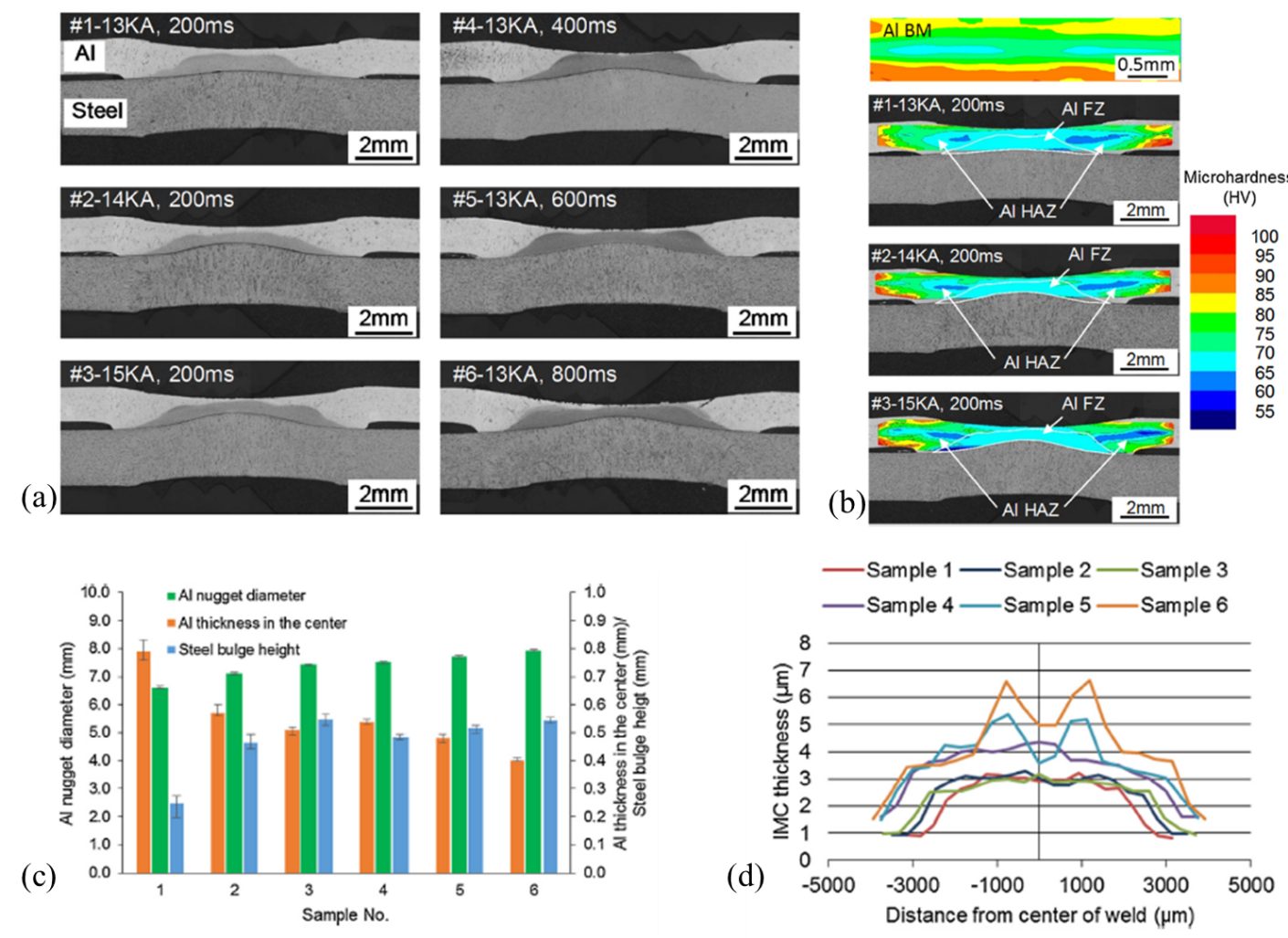
Figure 7: (a). Cross section micrographs of Al/steel RSWs generated by different welding schedules. ,(b) Microhardness contours of Al BM and Al sheets of Al/steel welds. ,(c) Comparison of Al/steel weld dimensions. & (d) Comparison between lap shear stress and average IMC thickness.S-15
Figure 8 shows the relationship between the IMC layer thickness and peak load failure. At 13 kA, 14 kA and 15 kA as indicated by Sample 1, Sample 2 and Sample 3, respectively, in Figure 8(a). Moreover, it is reported that the thinner IMC layer (<3 µm) resulted in bottom pullout failure. Figure 8(b) shows the governing parameters for interfacial or nugget pull out failure.
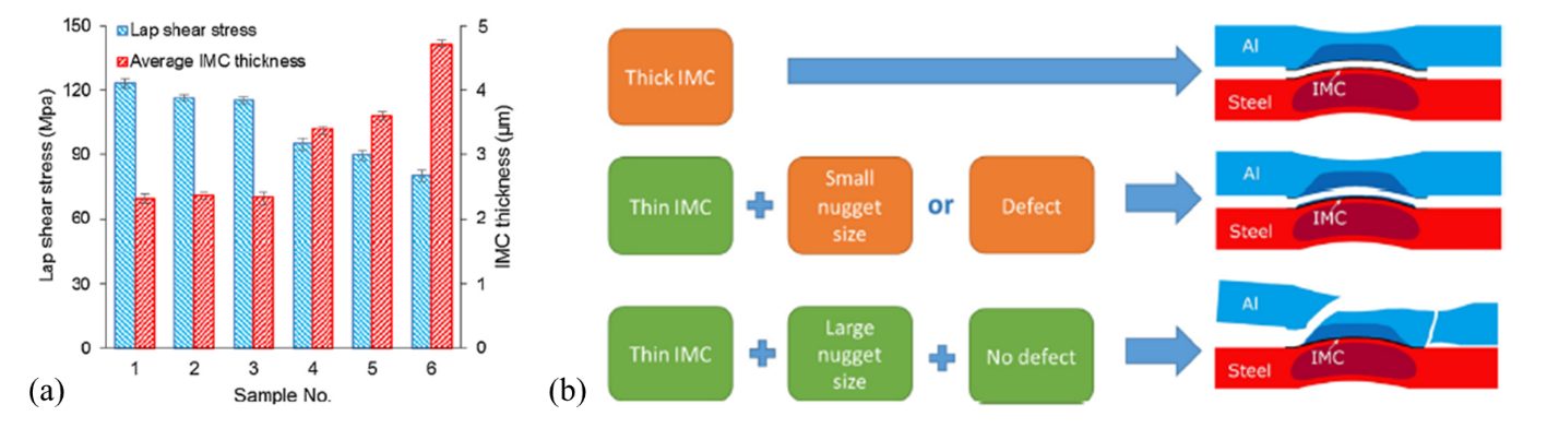
Figure 8: (a) Relationship between peak strength and IMC layer, (b) Model depicting the governing failure mode.S-15