More Reveals of the Steel E-Motive Autonomous Vehicle Demonstration

More Reveals of the Steel E-Motive Autonomous Vehicle Demonstration

WorldAutoSteel has a 30-year legacy of steel demonstration all the way back to the Ultra-Light Steel Auto Body (ULSAB), whose engineering report is still being downloaded from our worldautosteel.org site today. The one you may remember best is the FutureSteelVehicle (FSV), results of which we launched in 2011. FSV demonstrated steel innovation for not only Battery Electric vehicles (BEV) but also Fuel Cell vehicles (FCV). Steel E-Motive is the sixth of our global steel industry programs.

So Why Mobility as a Service?

The Automotive sector is undergoing the most rapid change in 40 years. This transformation shifts our thinking – from the movement of vehicles to the efficient movement of people and goods. Over the past eight years, we have conducted extensive research into global trends such as urbanization, transport emissions reduction, as well as the waning interest in vehicle ownership among the young and old. This is especially prevalent in megacities characterized by pollution, congestion, limited parking and enormous ownership costs. Our research concluded that mobility as a service (MaaS) will grow exponentially in high population areas and would place a significant challenge on vehicle design and manufacturing. Therefore, we needed to make sure we as an industry were active and visible in providing STEEL solutions in this new market place.

Steel E-Motive will demonstrate the benefits of steel, linking the properties of the material to the required architectures and attributes for MaaS vehicles.

This program will demonstrate the benefits of steel, linking the properties of the material to the required architectures and attributes for MaaS vehicles. It connects us with original equipment manufacturers (OEMs) and future mobility providers (FMPs), reinforcing steel’s advantages in strength, durability, sustainability and affordability.

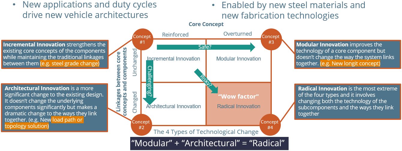
An autonomous BEV structure aligns perfectly with steel’s best attributes, however most new concepts trial alternative materials. The global steel industry is investing significantly in product and fabrication development to continually prepare for the next challenge. High Strength and Advanced High-Strength Steel (AHSS) portfolios have grown from the 11 highlighted in the ULSAB program, to more than 60 grades available for use in designing and optimizing Steel E-Motive’s autonomous BEV architecture. Third Generation AHSS (3rd Gen AHSS) will have a prominent role in Steel E-Motive’s body-in-white, taking strength levels ever higher while improving manufacturability. And our industry continues to evolve Press Hardened Steels (PHS) with strength levels upwards of 2000 MPa.

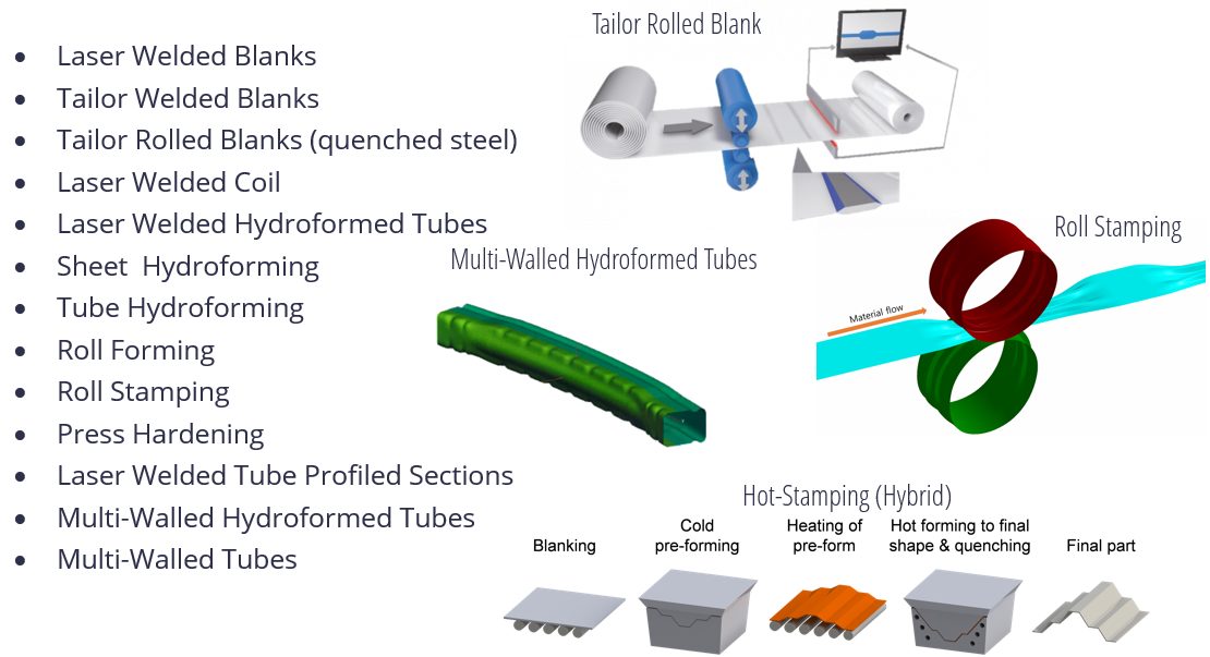
Finally, efficient fabrication processes such as roll stamping, press hardening, and hydroforming use less steel and therefore contribute lower vehicle production emissions. These are the details being highlighted in Steel E-Motive, where we hope to demonstrate that only Steel can make it Real.

Steel E-Motive: A game changing, world first?

Many OEM’s and mobility service providers follow the typical vehicle development process where they adapt an existing vehicle structure to the new vehicle requirements. We don’t have that in Steel E-Motive We believe Steel E-Motive is one of the world’s firsts.

  • The first for a Level 5 autonomous vehicle that is compliant with global high-speed crash requirements.
  • The first autonomous vehicle to be a conventional high-volume stamped steel body construction, creating an affordable platform for the mobility service provider.
  • First to offer a competitive, robust, and sustainable MaaS solution.

For engineers, being first is very exciting but a little nerve wracking – there are no benchmarks out there. There is less to “hang on to.”  We’re on our own. Target setting is more challenging; we are the benchmark. Time will tell if we make it to the automotive hall of fame.

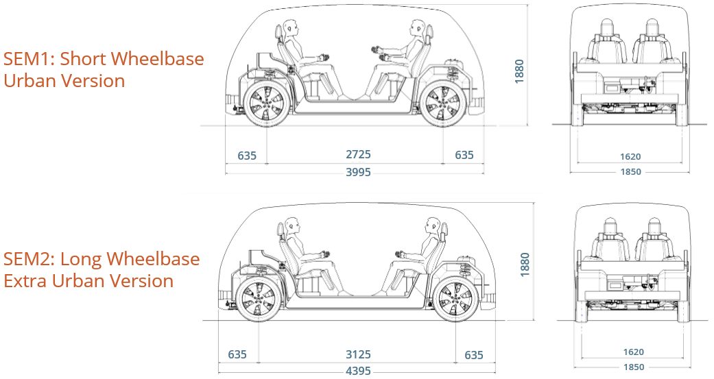
We are producing concepts for two BEVs based on a single modular platform.  SEM1 (Figure 1) is a front-wheel drive short wheelbase urban version for inter-city travel for four passengers. It has a compact design and vehicle footprint, comparable in footprint to a European B/C segment size. SEM2 (Figure 2) is an all-wheel drive, long wheelbase extra urban version designed to carry up to six passengers. It has an adaptable interior volume that can result in additional luggage capacity compared to SEM1.

Figure 1: SEM1 Vehicle Specifications

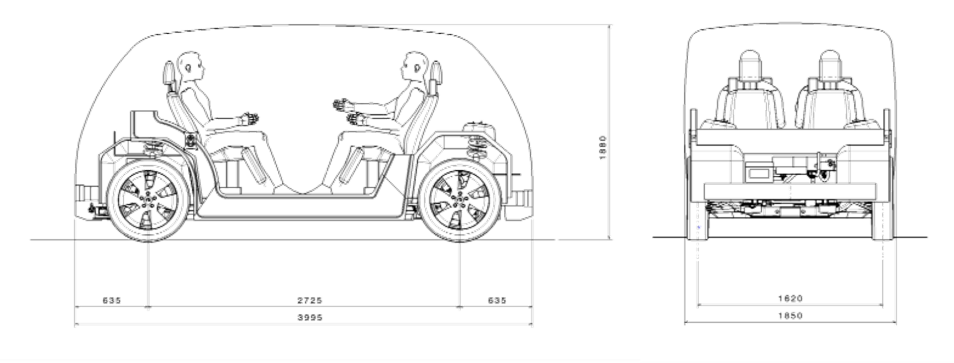
Figure 1: SEM1 Vehicle Specifications  (© WorldAutoSteel 2022)


Figure 2: SEM2 Vehicle Specifications

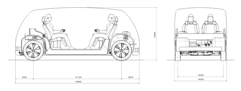
Figure 2: SEM2 Vehicle Specifications (© WorldAutoSteel 2022)


Body in White Steel Usage

Steel E-Motive benefits from a broad portfolio of steel grades and fabrication process, as identified by our member steel experts. The design is nearly finalized, and material selections are being evaluated against various performance targets with the representative structure shown in Figure 3 with high PHS usage at this stage in the design (as of May 2022). This is mainly driven by the safety requirements. Steel E-Motive BIW steel and steel technologies include:

  • Right steel grade in the right place
  • Significant proportion of >1500MPa grades, primarily for occupant and battery intrusion zones
  • Mixture of stamped, roll formed, roll stamped, press hardened steel and hydroformed parts
  • Spotweld, laser weld and structural adhesive

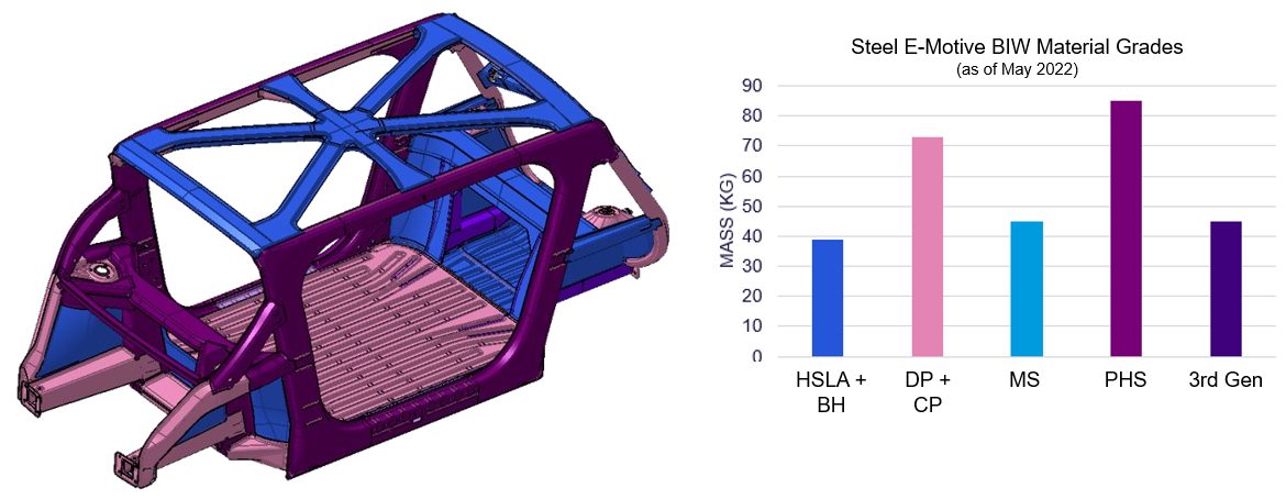
Figure 3: Steel E-Motive’s Body-in-White Steel usage as of May 2022. (© WorldAutoSteel 2022)


At the Core of the Steel E-Motive Concept Is an Innovative Battery Design

Figure 4 shows Steel E-Motive’s battery frame design’s construction:

  • Battery modules and cooling plates are mounted to an AHSS carrier frame (off-line).
  • The carrier frame is mounted to the body structure (in general assembly).
  • The BIW floor acts as the top cover and provides sealing.
  • The AHSS bottom cover plate provides impact protection.

This design provides significant cost and weight savings, as well as improved NVH. This extremely efficient package does not compromise safety and enables a flat floor with a lower step-in height.

Figure 4:  Steel E-Motive Battery package assembly. (© WorldAutoSteel 2022)


Competitive Body Stiffness with an Open B-Pillarless Body Structure

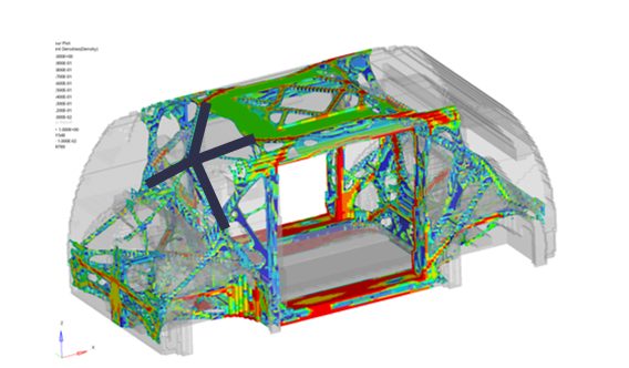
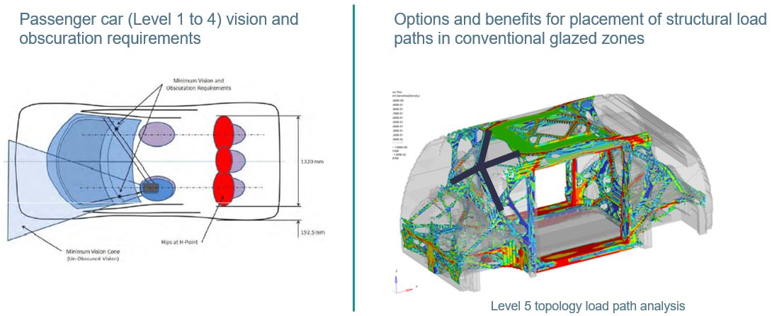
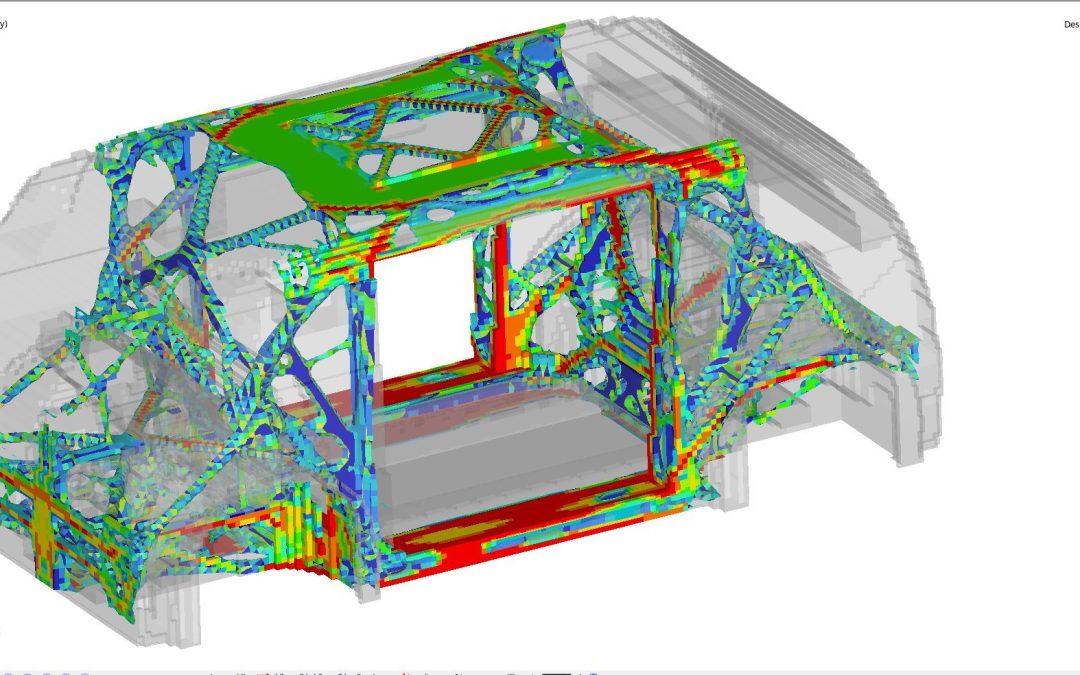
With clean sheet design, and generally less package constraints in a Level 5 vehicle, our design teams have had more freedom to engineer and optimize the crash and stiffness structural loadpaths. We used topology, optimization, and Virtual Reality tools to determine the most efficient structural loadpaths (Figure 5). The results informed the joint designs and enabled optimization of the joining and structural adhesives. These steps and the advantage of steel’s high modulus resulted in impressive performance.

Figure 4: Topology Load Path Optimization

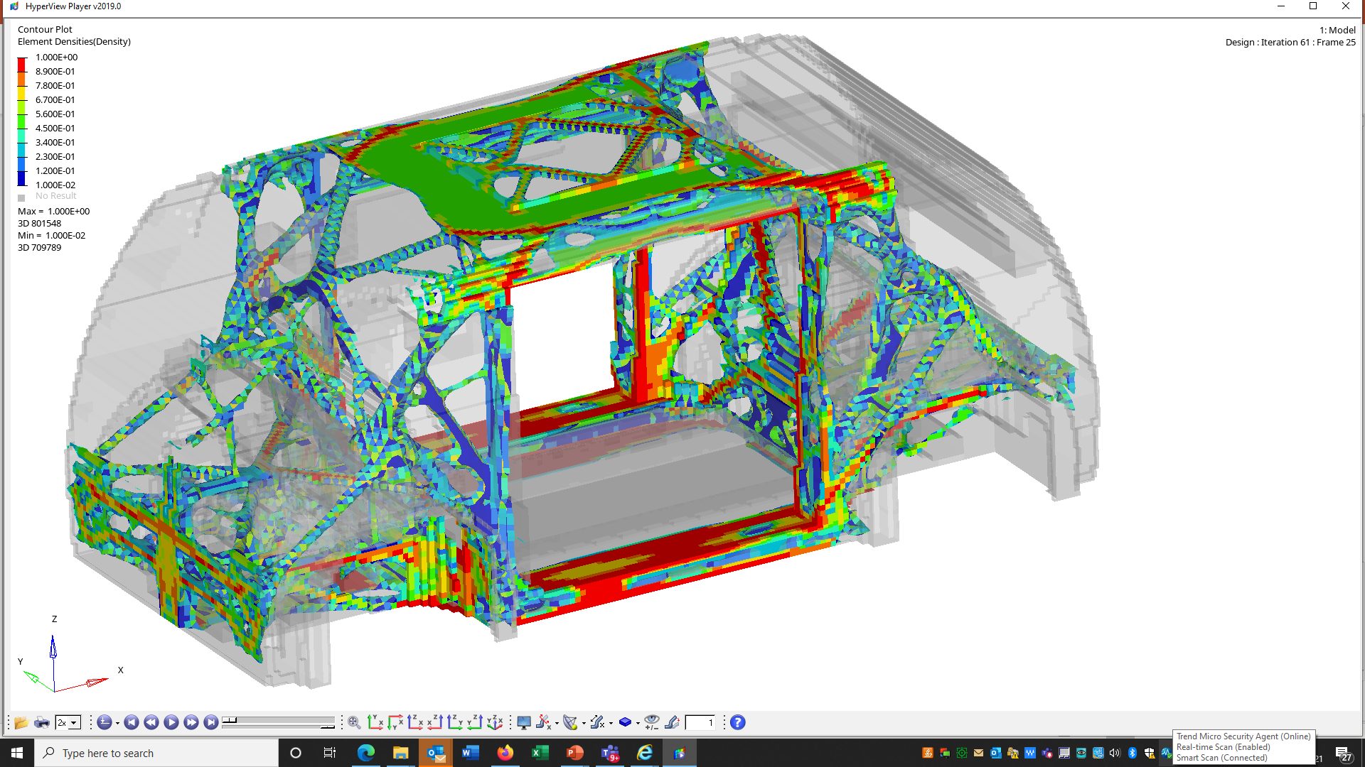
Figure 5: Topology Load Path Optimization. (© WorldAutoSteel 2022)


The approach for achieving body stiffness was as follows. Results are shown in Figure 6 following.

  • Topology load path optimization
  • Appropriate section size, profiles, part integration and flange / joint design
  • Strut towers integrated with key body members, such as A-pillars, vertical dash brace
  • Contribution from structural battery frame and battery cover closing, roof structure trusses
  • Rigidly connected front and rear subframes
  • Optimized joining and use of structural adhesives
  • Capitalizing on the Inherent high modulus of steel

Figure 6: SEM Torsional Rigidity animation. (© WorldAutoSteel 2022)
Static torsional stiffness 38,000Nm/deg
Global trimmed BIW modes >28Hz
Local attachment static stiffness ten times bushing stiffness

Front Crash Structure Engineered to Balance the Requirements of 56kph USNCAP FFB, IIHS ODB, IIHS SORB and EuroNCAP MPDB Load cases

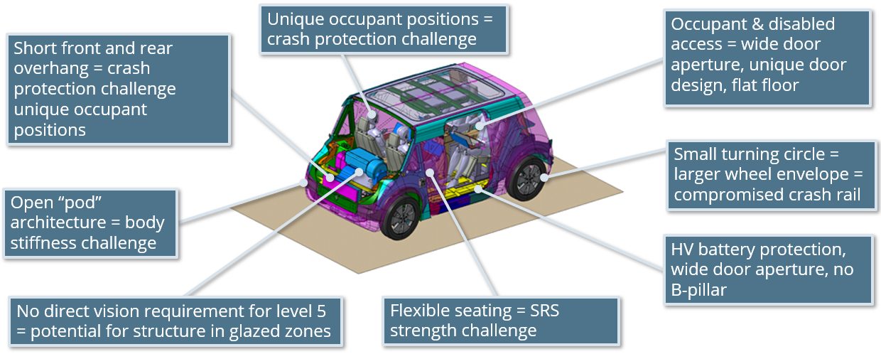
One of the most challenging aspects of the Steel E-Motive program has been achieving the front crash performance that minimizes occupant injury. The challenge has been compounded by the overall compact size of the vehicle and the short front overhang dimensions, meaning less space to manage and balance the required crush energy with intrusion resistance.

For the IIHS 25% Small Overlap test, we worked from the outset to achieve a barrier “glance off.” The goal is to deflect the vehicle off the barrier by the time the barrier reaches the hinge pillar. This results in a reduced amount of vehicle kinetic energy converted to crush energy. The vehicle continues after the impact with some onward velocity and kinetic energy. This strategy results in reduced intrusion to the passenger compartment and a much lower vehicle pulse (below 20g), which translates into lower occupant injury. We are very excited by this outcome, as in our benchmarking we have not seen many (if any) vehicles of this size managing to achieve a glance off for this test. Figures 7 and the bullets following provide a look at the results.

Figure 7: IIHS 25% Small Overlap test. (© WorldAutoSteel 2022)

  • IIHS “good” rating achieved (based on predicted intrusions).
  • Our strategy for IIHS Small Overlap test was to achieve a “glance off” the barrier, which is a significant challenge given the vehicle’s short front overhang.
  • Front suspension engineered to detach on impact. This is important for achieving glance off.
  • Glance off results in some continued onward vehicle velocity after the impact.
  • This results in reduced crush energy, lower vehicle pulse and intrusions = enhanced occupant protection


Figure 8 points out features of the front crash structure. Most of the crush energy in FFB and ODB is absorbed by conventional longitudinal mid-rails, which are made of cold stamped, tailor welded blank Dual Phase steels. The plan view angle of the longitudinals has been optimized to provide load reaction early in the SORB event while remaining largely inside of the SORB barrier.

Front crash structure engineered to balance the requirements of 56kph USNCAP FFB, IIHS ODB, IIHS SORB and EuroNCAP MPDB load cases.

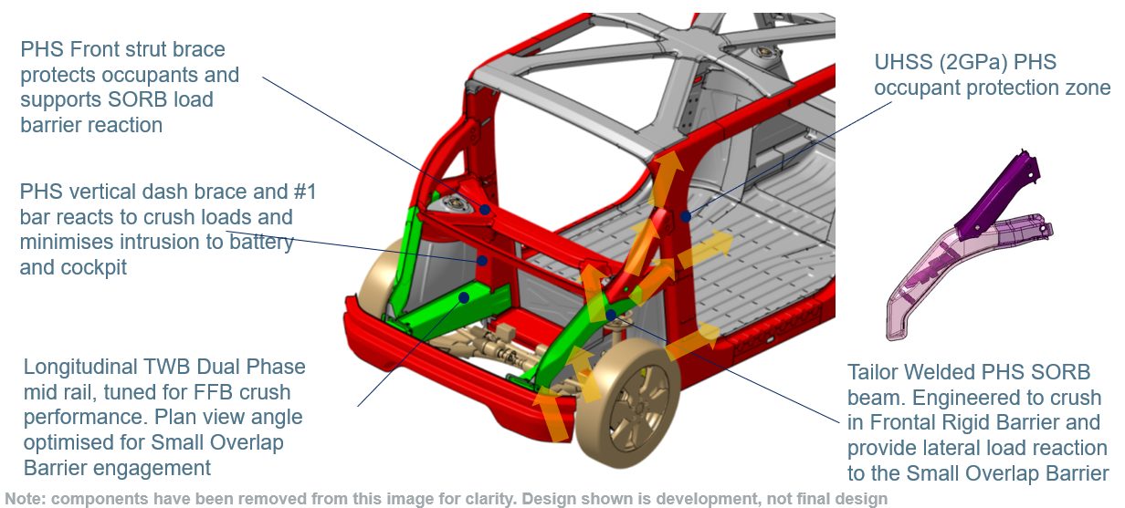
Figure 8: Front crash structure engineered to balance the requirements of 56kph USNCAP FFB, IIHS ODB, IIHS SORB and EuroNCAP MPDB load cases. (© WorldAutoSteel 2022)


Following in Figures 9 and 10 are animations of the FFB results:

Figure 9: USNCAP 56kph Rigid Barrier – Top View. (© WorldAutoSteel 2022)
Figure 10:  USNCAP 56kph Rigid Barrier – Side View. (© WorldAutoSteel 2022)


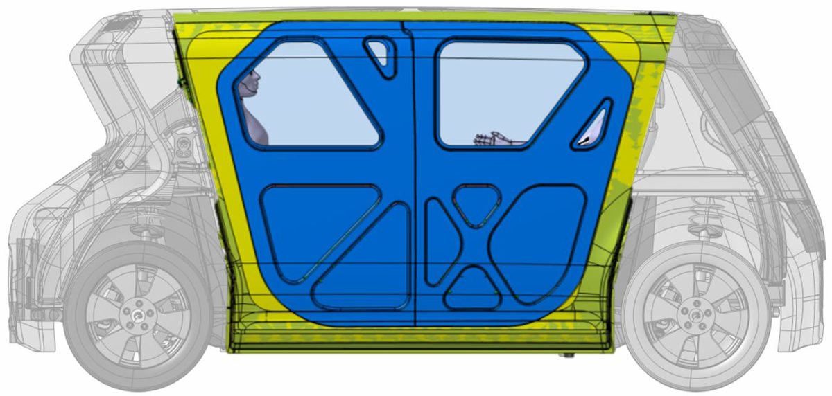
MaaS vehicles will need to accommodate quick ingress and egress as well as provide comfort and safety for the occupants. Consequently, we have flipped the front occupant around to a rear facing configuration and provided a B-Pillarless wide door aperture to enable comfortable and quick access for passengers. This changes the approach required for occupant protection in a front crash. Effectively we are dealing with a high-speed rear impact situation for the occupant. Current rear impact tests cover lower speed rear end shunts. Figure 11 notes the key points and challenges that Steel E-Motive is designed to meet.

Different approach and considerations are required for the protection of rear facing front occupants. We are effectively dealing with a high speed rear impact event

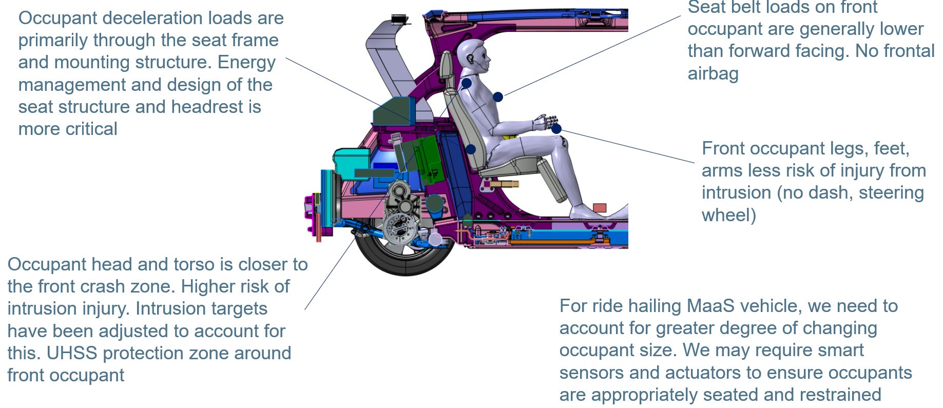
Figure 11: Different approach and considerations are required for the protection of rear facing front occupants. We are effectively addressing a high-speed rear impact event.  (© WorldAutoSteel 2022)


Side Crash Structure Consists of Absorption and Intrusion Prevention Zones, Compensating for Large Body Aperture

The side structure includes roll-stamped martensitic door waist rail beams and a one-piece Tailor Welded Blank, Press Hardened Steel door ring outer. A- and C-pillars in line with occupants provide good side impact protection. (You can learn more about the door design in our May blog).

In the section AA schematic in Figure 12 the TRIP690 hydroformed tube interlocking door B-pillar is shown (wrapped over the rocker and cantrail). The load travels through the side impact crush “hex” beam, which is a two-piece roll formed DP590 component.

SIDE CRASH STRUCTURE CONSISTS OF ABSORPTION AND INTRUSION PREVENTION ZONES, COMPENSATING FOR LARGE BODY APERTURE

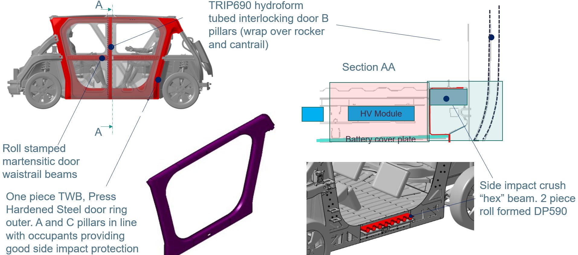
Figure 12: Side crash structure consists of absorption and intrusion prevention zones, compensating for large body aperture. (© WorldAutoSteel 2022)


Steel E-Motive Design Demonstrates Good Side Crashworthiness and Good Levels of Occupant and Battery Protection

In addition to occupant protection tests, additional side impact load cases have been simulated to ensure optimal battery protection. The design maintains a less than 30 mm clearance to the battery.

In reviewing the design according to IIHS standards and based on the predicted intrusions, we are confident this vehicle would achieve an IIHS “good” rating.  See Figures 13 and 14 following:

Figure 13: USNCAP 32kph side pole (battery protection). (© WorldAutoSteel 2022)
In addition to occupant protection test, additional side pole load cases to ensure battery protection
>30mm clearance to battery maintained


Figure 14: IIHS 60kph side barrier II (occupant protection). (© WorldAutoSteel 2022)
IIHS “good” rating (based on predicted intrusions).


Total Cost of Ownership: Vehicle and Body Is Designed for Conventional Fabrication and Assembly Processes

The Steel E-Motive body has been designed with low cost in mind to provide the foundation for a lower total cost of ownership for fleet owners. The steel body design is optimized to maximize material utilization and minimize scrap rate. Steel E-Motive is suitable for >250,000 units/year production and is compatible with existing global automotive manufacturing facilities using conventional press and fabrication tools. We are also using Life Cycle Assessment as an integral part of the engineering process to ensure that Steel E-Motive is responsible for the lowest possible emissions throughout its entire life cycle. We will report on environmental performance and sustainability as a part of our final results.

Steel E-Motive Key Outcomes

The Steel E-Motive program is delivering an exciting futuristic vehicle, optimized from the ground up for autonomous MaaS application. We are addressing key challenges through careful design, application of simulation tools and efficient use of the latest Advanced High-Strength Steels and fabrication processes. Steel’s inherent characteristics of low production emissions, lightweighting capabilities for mass efficiency, infinite recyclability and product durability underscores its suitability as an integral part of stakeholder strategies to offer sustainable mobility solutions, today and in the future.

Be sure to follow us on our journey as we enter our final months of design, engineering and reporting by subscribing at the Steel E-Motive website. We welcome your questions about this program using the Comment box below.


Images are not for use without permission. Contact steel@worldautosteel.org.


Designing For Vehicle Crash Requirements that Don’t Yet Exist

Designing For Vehicle Crash Requirements that Don’t Yet Exist

Steel E-Motive’s AHSS A- and C-Pillar placement provide good occupant protection in side pole crash scenarios. The A- and C-Pillar combined with AHSS door ring and door reinforcements compensate for the removed B-Pillar.

Since June 2020, we’ve been working with our engineering partners, Ricardo, on Steel E-Motive, a vehicle engineering program which is developing virtual concepts for two fully autonomous and connected electric vehicles designed for mobility as a service (MaaS) applications. We are using Advanced High-Strength Steel (AHSS) technologies and products to design autonomous vehicle concepts to enable MaaS solutions which are safe, affordable, accessible and environmentally conscious.

Steel E-Motive engineering and validation will be completed in 2022, at which time we will prepare communication and delivery of the final results. But right now, we are in the midst of crash simulation and material optimization to solve the new challenges posed by these vehicles.

Steel E-Motive is designed to operate in a mixed traffic mode operation (both driver-operated and autonomous vehicles); hence the vehicle should meet the current and future global high-speed crash test standards. The compact vehicle dimensions and proportions result in relatively short front and rear overhangs. To enhance user experience and take advantage of full autonomy, the front occupants are positioned in a rear facing configuration presenting a more significant challenge for crashworthiness in frontal impact. This requires a revised front crash strategy and load management approach for Steel E-Motive.

Neil McGregor, Steel E-Motive’s Chief Engineer, has written a blog about it, and you can find it posted on our Steel E-Motive website (web spiders prohibit us from duplicating the article here).  Take a moment to read it there, but feel free to ask questions or comment about it here!

Steel Structures for Autonomous Vehicles

Steel Structures for Autonomous Vehicles

The WorldAutoSteel Steel E-Motive program has been moving along now for nearly a year, and we’d like to share an update with you, our engineering colleagues, on some of the design decisions we’re facing. If you recall, the Steel E-Motive program is designing vehicle concepts for Mobility as a Service (MaaS), characterized by autonomous, electric, ride sharing vehicles.


Some Background

We partnered with Ricardo headquartered in the UK to conduct the design and engineering of the vehicles. Ricardo was selected for their well-known reputation for innovation, their demonstrated knowledge of vehicle powertrains and electrification and their commitment to sustainable transportation. Our steel members subject matter experts work with Ricardo via various teams and working groups to push the envelope of steel applications. And given our pandemic, all of this currently occurs via virtual meetings.

Targeting technologies available for deployment in 2030+, we are considering the impacts to vehicle manufacturers, fleet operators and the ride hailing customer, as MaaS inevitably leads to an increase in demand for vehicle sharing, rental models and ride-hailing services over the next decade. We can represent these requirements as shown in Figure 1. On the left you’ll see broad needs for the critical stakeholders including space efficiency, flexibility and total cost of ownership. Those requirements translate into 12 key considerations for the mobility service provider, shown on the right, aimed at delivering value to customers and a sustainable and profitable business model. These considerations then require innovative design, engineering and materials applications.

Figure 1: MaaS key attributes and functions.

Figure 1: MaaS key attributes and functions.


There are four main phases to Steel E-Motive (Figure 2). Phase 0 was a 3-month pre-study, beginning 30 June 2020, to review and confirm vehicle targets, essentially defining the foundations, goals and approach for the project. On 1 October 2020, we entered the Phase 1 concept engineering, exploring the challenges and steel solutions for Level 5 autonomous vehicles. Essentially, we are designing the body structure in this Phase, utilizing CAE tools to guide us. Phase 2 focusses on further refinement and optimization of the selected body concept, and ensuring the design is fully validated as there will be no working prototypes or hardware produced in the project. Phase 3 will be the roll out and dissemination activities, although you will see from the Steel E-Motive website and blogs that we are continually releasing material throughout the project.

Figure 2: Project timing and key activities.

Figure 2: Project timing and key activities.


We’ll be disclosing detailed targets and specifications later in the program, but Figure 3 provides overall dimensions. Battery electric will be the primary propulsion with competitive range. There are two variants: urban for inner city and shorter journeys, and an extra-urban variant for longer city-to-city (or city-to-airport) journeys. With Level 5 autonomy, there are no direct driver interfaces such as the steering column and pedals. You can see from the Figure that the vehicles are fairly compact. The urban variant sits between a European B and C segment in size. The extra-urban vehicle has a stretched wheelbase and can accommodate up to six passengers and a greater luggage capacity.

Figure 3: SEM vehicle technical specification and dimensions – base vehicle geometry.

Figure 3: SEM vehicle technical specification and dimensions – base vehicle geometry.


The vehicles will be engineered and purposed for global application; therefore, we are considering the major global crash and safety standards and load cases. High volume production is targeted, greater than 250,000 units per annum, and a hypothetical production date of 2030, which influences the steel grades and fabrication processes considered. Third Generation AHSS (3rd Gen AHSS) and press-hardened steels continue to evolve with higher strength and improved formability. Between these innovative product capabilities, we are addressing the challenges associated with Mobility as a Service and tackling geometries that otherwise would have been difficult to produce.

To further assist in the design and manufacture of efficient vehicle structures, there are many new manufacturing processes, such as roll forming and hot stamping, that help fabricate these stronger materials effectively, while often doubling material use efficiency. Figure 4 provides a list of technologies that will be considered for Steel E-Motive.

Figure 4: Steel technologies included in SEM’s portfolio.

Figure 4: Steel technologies included in SEM’s portfolio.


With the portfolio of steel product and manufacturing processes already available and the addition of those forecasted for future commercial availability, we are expecting innovations that will be a roadmap for future mobility vehicle manufacturers.

Our end goal is to demonstrate multi-purpose opportunities for the vehicles via a modular architecture enabled by the application of innovative steel solutions. These solutions will help Steel E-Motive achieve a low environment footprint measured over the vehicle Life Cycle, and meet global crash standards while delivering the lowest Total Cost of Ownership (TCO).

To reach our goal of demonstrating steel innovation in this program, we are using a theoretical frameworkH-2 as a guide, shown in Figure 5, considering innovation at an architectural level. That is, using body structure load paths shown in the vertical axis, and modular innovation for the major body components such as battery enclosure, side/crash rails, shown in the horizontal axis. Combining innovation levels and types of the two axes should enable us to demonstrate radical innovation in Steel E-Motive.

Figure 5: Steel E-Motive explores and demonstrates steel innovation. Exploring “modular” and “architectural” innovations for 2030 production.

Figure 5: Steel E-Motive explores and demonstrates steel innovation. Exploring “modular” and “architectural” innovations for 2030 production.

Design Challenges

Figure 6 reveals an early or basic Steel E-Motive architecture. You can see that Level 5 autonomy creates both design freedoms that allow new occupant seating positions, while also creating challenges for short front and rear overhangs. We have an open pod-type structure with large door apertures for enhanced occupant ergonomics.

Figure 6: Challenges and opportunities of Level 5 autonomous MaaS battery electric vehicle.

Figure 6: Challenges and opportunities of Level 5 autonomous MaaS battery electric vehicle.


Passenger comfort is key for MaaS vehicles. The open pod structure may give challenges with the air cavity mode coupling with structural modes. With occupants in different positions, we have different NVH source-path-receiver paths to consider. The larger door aperture gives us an inherent deficiency in overall body structure stiffness, for which we need to compensate. As with any BEV, the mass of the battery suspended on the lower structure may reduce body modes to frequencies that interact with other vehicle systems such as suspension modes. With a lot of emphasis on lower structure crash zones and battery protection, we may encounter some lower frequency upper body modes (such as lozenging), especially as we are targeting low overall body mass. These NVH risks and challenges are being addressed by taking a modal mapping approach, utilizing steel’s inherent high structural stiffness properties and undertaking thorough NVH simulation throughout the engineering phases.

Level 5 autonomy removes the requirements for driver vision and obscuration, but we do need to acknowledge passenger comfort issues, such as motion sickness. Consequently the designs consider a good level of outward visibility. However, we now have the freedom to place structure where we could not previously. We are using 3D topology FEA tools to help determine the optimum placement of structure in the body, and we have allowed the tool the freedom to place structure in the front and rear glazed areas. In the Figure 7 example, the software is recommending some structural members across the front windscreen, and further analysis shows that this has the potential to give us an overall Body-In-White weight saving as the load paths are more evenly distributed.

Figure 7: Level 5 autonomy removes the driver vision and obscuration requirements—an opportunity for new solutions.

Figure 7: Level 5 autonomy removes the driver vision and obscuration requirements—an opportunity for new solutions.


To summarize the Steel E-Motive engineering activities, we are currently exploring the numerous challenges and opportunities that Level 5 autonomous BEVs provide us. We are in the concept phase, investigating both the overall body structure layout and load paths, as well as developing components and modules utilizing the unique properties of steel.

We expect to complete the program with full virtual concepts by December 2022. Our plans are to unveil more and more of the design concepts over the months to come, and we’ll be using virtual reality and other tools to communicate the concepts’ engineering. We invite you to subscribe at the website to receive all the news that will be coming out of the program, including more technical details as they become available. You can do that at www.steelemotive.world. We’re excited to share Steel E-Motive innovations in the future!


Steel Grades

Steel Grades

Steel Grades

See the brief Tutorial on using the Steel Grades search.

TitleTagsCategorieshf:tagshf:categories
Resistance Spot Welding: 5T Dissimilar Steel Stack-ups for Automotive Applications, , , , , , , , , , , , , , , 5t-stack-ups ahss resistance-spot-welding rsw rsw-parameters rsw-procedures stack-upsahss blog homepage-featured-top joining main-blog news resistance-spot-welding rsw-of-dissimilar-steel steel-grades tool-die-professionals metallurgy resistance-welding-processes
Stronger AHSS Knowledge Required for Metal Stampers, , , , , , , , , , , , , , ahss coil-processing heat-treatment metal-stamping tooling1stgen-ahss 2ndgen-ahss 3rdgen-ahss ahss blog homepage-featured-top main-blog news production-managers steel-grades tool-die-professionals metallurgy
Steel E-Motive: A Future Mobility Concept Paving the Way to Net Zero Emissions, , , , , , , battery-electric-vehicles electric-vehicles future-mobility level-5-autonomy steel-e-motiveahss blog main-blog news steel-grades metallurgy
Steel E-Motive: Autonomous Vehicles That Only Steel Can Make Real, , , , , , , , , advanced-high-strength-steels ahss steel-emotive3rdgen-ahss ahss blog general main-blog metallurgy news steel-grades
Talk Like a Metallurgist, , , , , , , , , , , , defining-steel metallurgy steel-definitions steel-grades steel-nomenclature1stgen-ahss 2ndgen-ahss 3rdgen-ahss ahss blog conventional-h-s-s lower-strength-steels metallurgy steel-grades
Martensite, , , , , , , , , , , , , 1stgen-steel ahss astm-a980m cold-stamping mart martensite martensite-metallurgy microstructural-components microstructure ms sae-j2745 vda-239-1001stgen-ahss ahss steel-grades metallurgy
Press Hardened Steels, , , , , , , , , , , , , , , , , , , , , , , , , , , , , , , 1stgen-steel 3rd-gen ahss alsi as-coating bake-hardenability boron-steel critical-cooling-rate direct-press-hardening e-billur hot-forming hot-press-forming hot-stamped-boron hot-stamping indirect-press-hardening martensite medium-mn phs phs-grades-over-1500-mpa phs-grades-with-tensile-strength-approximately-1500-mpa pqs-grades-with-high-elongation pre-cooled-direct-process press-hardening press-hardening-steels press-quenched-steel quenching stainless vda-239-500 zn-coated-phs1stgen-ahss ahss press-hardened-steels steel-grades metallurgy forming
Defining Steels, , , , , , , , , , , , , , , , , , , 3rd-gen 3rd-generation ahss banana-diagram bubble-diagram defining-ahss defining-uhss football-diagram global-formability-diagram hance-diagram local-formability local-global-formability-map microstructural-components microstructure nomenclature syntax tensile terminology uhss yieldmetallurgy
Dual Phase, , , , , , , , , , , , , , , , , 1stgen-steel ahss astm-a1088 bake-hardening-effect dp dual-phase en-10338 ferrite jfs-a2001 jis-g3135 martensite microstructure sae-j2745 strain-hardening-exponent vda-239-100 work-hardening1stgen-ahss ahss steel-grades metallurgy
Transformation Induced Plasticity (TRIP), , , , , , , , , , , , , , , , , , , , , 1stgen-steel 3rd-generation ahss astm-a1088 bainite en-10338 ferrite jfs-a2001 martensite microstructure retained-austenite sae-j2745 strain-hardening-exponent transformation-induced-plasticity trip trip-effect trip-metallurgy vda-239-100 work-hardening1stgen-ahss 3rdgen-ahss ahss steel-grades metallurgy
Complex Phase, , , , , , , , , , , , , , , , , , , 1stgen-steel ahss astm-a1088 bainite bendability bending complex-phase cp en-10338 ferrite local-formability martensite microalloy microstructural-components microstructure precipitation-strengthening retained-austenite vda-239-1001stgen-ahss ahss steel-grades metallurgy
Ferrite-Bainite, , , , , , , , , , , , , , , , , , , , , 1stgen-steel ahss bainite cut-edge-stretching edge-stretchability en-10338 fb ferrite ferrite-bainite hhe hole-expansion hole-extrusion hole-flanging hot-rolled-steel jfs-a2001 microstructural-components microstructure stretchability stretching vda-239-1001stgen-ahss ahss steel-grades metallurgy
Ultra-Low Carbon (DDS – EDDS), , , , , , , , , , , , dds deep-drawing-steel edds extra-deep-drawing-steel ferrite ferrite-ultra-low-carbon-mild-steel microstructure mild-steel ulc ultra-low-carbon vacuum-degassed vd-iflower-strength-steels steel-grades metallurgy
3rd Generation Steels, , , , , , , , , , , , , , , , , , , , , , , , 3rd-gen advanced-high-strength-steels ahss carbide-free-bainite cfb ch complex-phase-high-ductility cp-hd dh downgauging dp-hd dual-phase-high-ductility high-ductility intercritical-anneal manganese medium-mn overaging qp quench-and-partition tbf third-generation trip-assisted-bainitic-ferrite trip-effect3rdgen-ahss ahss steel-grades metallurgy
Carbon-Manganese (CMn), , , , , , , , , , , , , astm-a1008m c-mn carbon carbon-and-manganese carbon-manganese cmn conventional-high-strength-steel high-strength-steel jfs-a2001 jis-g3135 manganese structural-steel yield-strengthconventional-h-s-s steel-grades metallurgy
High Strength Low Alloy Steel, , , , , , , , , , , , , , , , astm astm-a1008m c-mn carbon-manganese cmn conventional-high-strength-steel en-10268 high-strength-low-alloy hsla jfs-a2001 jis-g3135 la microalloy precipitation-strengthening vda-239-100 yield-strengthconventional-h-s-s steel-grades metallurgy
Mild Steels, , , , , , , , , , , , , , , , , astm-a1008m dq dqak dqsk draw-quality-steel drawing-steel ds en-10130 ferrite jfs-a2001 jis-g3141 low-carbon microstructure mild-steel ulc ultra-low-carbon vda-239-100lower-strength-steels steel-grades metallurgy
Interstitial-Free High Strength, , , , , , , , , , , edds en-10268 if if-hs if-rephos interstitial-free-high-strength jfs-a2001 rephosphorized ulc vd-if vda-239-100conventional-h-s-s steel-grades metallurgy
Bake Hardenable, , , , , , , , , , , , , , , , , , , , , , astm-a1008m bake-hardenability bake-hardenable bake-hardening bake-hardening-effect baking-index bh bh-effect bhi carbon dent dislocations en10268 jfs-a2001 jis-g3135 microstructural-components paint-bake sae-j2575 strain-aging vda239-100 work-hardeningahss conventional-h-s-s steel-grades metallurgy
Twinning Induced Plasticity, , , , , , , , , , , , , , 2nd-gen ahss dynamic-strain-aging fe-mn manganese microstructure plc-effect portevin-lechatelier-effect strain-rate-sensitivity stretch-formability twinning-induced-plasticity twip twip4eu2ndgen-ahss ahss steel-grades metallurgy