Liquid Metal Embrittlement (LME) during Resistance Spot Welding (RSW) can cause cracks when welding advanced high strength steels. Recent advances in steel metallurgy, resistance spot welding processing and accompanying simulation tools have substantially improved the way that LME can be handled in industrial practice. This article gives a brief overview of easy measures to implement when LME might potentially occur during production.
Introduction
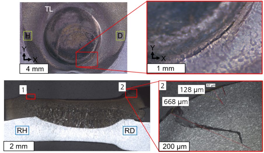
During resistance spot welding of zinc-coated advanced high strength steels (AHSS) liquid metal embrittlement -related cracking may be observed. Since LME is often associated with a reduction of steel’s mechanical properties, it is desired to control its occurrence during production. An exemplary LME crack, forced with increased weld heat and deliberate electrode misalignment, is shown below.
Figure 1: A typical LME crack created under laboratory conditions by deliberately increasing the welding time and introducing 5° electrode tilt
Over the past several years, LME has been a a focus in welding research. It is now well-understood to the degree that it can be predicted and avoided with easy measures. Below is an overview of four key steps to address the potential of LME during automotive production.
Obtain the latest steel grades from your steel supplier
Over the past decade, steel producers have released AHSS with improved chemical compositions, helping to significantly reduce the occurrence of LME iIt is beneficial to talk with steel suppliers and ask about their latest AHSS grades, as these are likely far less sensitive to LME than previously tested grades. A recent study commissioned by WorldAutoSteel demonstrated that all five chosen material stack-ups from current production data did not show any LME even under exacerbated conditions. Only by choosing an especially difficult material stack-up could LME be forced to appear at all to conduct the study.
Read up on the current state of research for LME
WorldAutoSteel has published two studies on liquid metal embrittlement: One focused on lab conditions and the second on real-life stamped components. These studies provide an overview of all aspects of LME and how to manage and avoid LME issues.
Establish in-house testing protocols to gauge the sensitivity of your material stack-ups
To investigate LME in-house, it’s critical to establish a testing protocol that forces the cracks to appear and allows for comparison of different steels, stack-ups and welding parameters. as there There is currently no industry-wide agreed-upon testing standard.
Still, there is a good selection of well-documented procedures to choose from. The easiest procedure is to increase the welding time until cracks start to appear – keep in mind that you need to remove the zinc coating before you can observe any cracks on the surface.
Other methods are based on so-called “Gleeble testing” or on deliberately introducing imperfections like tilted electrodes or large gaps into the welds. As you establish a testing procedure in your lab, you can use it to evaluate LME occurrence in the stack-ups that you want to implement into body-in-whites.
Think about implementing LME mitigation strategies in your most difficult welds
Suitable measures should always be adapted to the specific use case. Generally, the most effective measures for LME prevention or mitigation are:
Avoidance of excessive heat input (e.g. excess welding time, current)
Avoidance of sharp edges on spot welding electrodes; instead use electrodes with larger working plane diameter, while not increasing nugget-size
Employing extended hold times to allow for sufficient heat dissipation and lower surface temperatures
Avoidance of improper welding equipment (e.g. misalignments of the welding gun, highly worn electrodes, insufficient electrode cooling)
These measures can be implemented in the planning stage and in an ongoing production environment to increase the LME-free process windows.
In Conclusion
While Liquid Metal Embrittlement may present a challenge when welding AHSS, it’s no longer an unpredictable threat. Thanks to advancements in steel development, welding techniques, and testing methods, manufacturers have the tools they need to reliably mitigate LME during production.
Staying informed, working closely with steel suppliers, implementing smart testing protocols, and applying targeted welding strategies can help automakers maintain both strength and quality in AHSS joints. With this proactive approach, LME doesn’t have to stand in the way of innovation in automotive manufacturing.
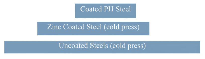
The discussions relative to cold stamping are applicable to any forming operation occurring at room temperature such as roll forming, hydroforming, or conventional stamping. Similarly, hot stamping refers to any set of operations using Press Hardening Steels (or Press Quenched Steels), including those that are roll formed or fluid formed.
Automakers contemplating whether a part is cold stamped or hot formed must consider numerous factors. This blog covers some important considerations related to welding these materials for automotive applications. Most important is the discussion on Resistance Spot Welding (RSW) as it is the dominating process in automotive manufacturing.
Setting Correct Welding Parameters for Resistance Spot Welding
Specific welding parameters need to be developed for each combination of material type and thickness. In general, the Hot Press (HP) steels require more demanding process conditions. One important factor is electrode force which should be higher for the HP steel than for cold press type steel of the same thickness. The actual recommended force will depend on the strength level, and the thickness of the steel. Of course, this will affect the welding machine/welding gun force capability requirement.
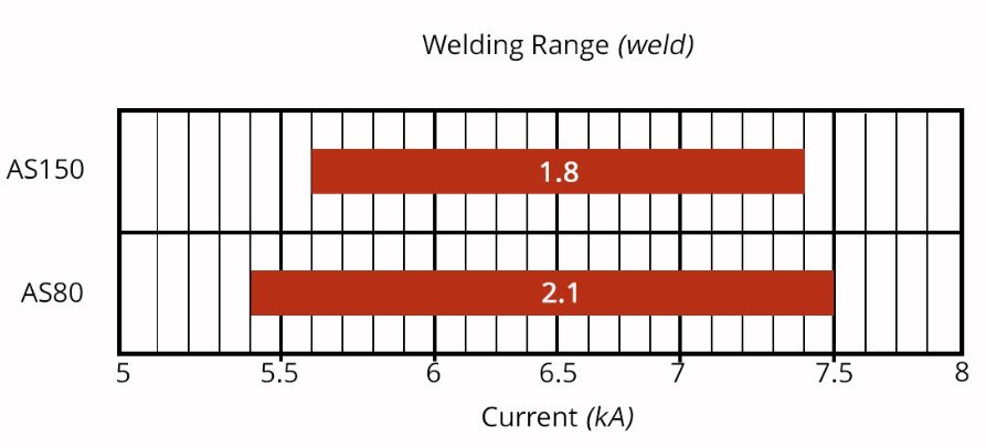
Another important variable is the welding current level and even more important is the current range at which acceptable welds can be made. The current range is weldability measurement, and the best indicator of the welding process robustness in the manufacturing environment and sometime called proceed window. Note the relative range of current for different steel types. A smaller process window may require more frequent weld quality evaluation such as for weld size.
Relative Current Range (process windows) for Different Steel Types
The Effect of Coating Type on Weldability
In all cases of resistance spot welding coated steels, it is imperative to move the coating away from the weld area during and in the beginning of the weld cycle to allow a steel-to-steel weld to occur. The combination of welding current, weld time and electrode force are responsible for this coating displacement.
For all the coated steels, the ability of the coating to flow is a function of the coating type and properties, such as electrical resistivity and melting point, as well as the coating thickness.
An example of cross sectioned spot welds made on Hot Press Steel with Aluminum -Silicon coating is shown below. It shows two coating thicknesses and the displaced coating at the periphery of weld. This figure also shows the difference in current range for the different coating thickness. The thicker coating shows a smaller current range. In addition, the Al-Si coating has a much higher melting point than the zinc coatings on the cold stamped steels, making it more difficult to displace from the weld area.
Hot Press Steel with Aluminum -Silicon
Liquid Metal Embrittlement and Resistance Spot Welding
Cold-formable, coated, Advance High Strength Steels such as the 3rd Generation Advanced HighStrength Steels are being widely used in automotive applications. One welding issue these materials encounter is the increased hardness in the weld area, that sometime results in brittle fracture of the weld.
Another issue is their sensitivity to Liquid Metal Embrittlement (LME) cracking. These two issues are discussed in detail on the WorldAutoSteel AHSS Guidelines website and our recently released Phase 2 Report on LME.
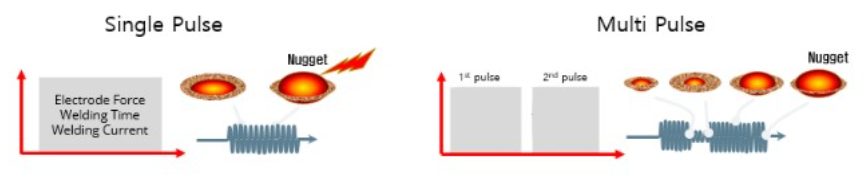
Resistance Spot Welding Using Current Pulsation
The most effective solution for the issues described above is using current pulsation during the welding cycle. A schematic description is shown below.
The pulsation allows much better control of the heat generation and the weld nugget development. The pulsation variables include the number of pulses (typically 2-4), the current level and time for each pulse, and the cool time between the pulses.
In summery, pulsation (and sometime current upslope) in Resistance Spot Welding proved to be beneficial for the following applications:
PHS steels
Coated Cold Stamped steels
Cold stamped Advance High Strength Steels
Multi materials stack-ups – As described in our articles here on 3T/4T and 5T Stack-Ups
Thanks is given to Menachem Kimchi, Associate Professor-Practice, Dept of Materials Science, Ohio State University and Technical Editor – Joining, AHSS Application Guidelines, for this article.
Press hardening steels (PHS) are typically carbon-manganese-boron alloyed steels, specifically designed for hot forming process in the automotive industry. They are also commonly known as:
Press Hardening Steels (PHS)
Hot Press Forming Steels (HPF), a term more common in Asia
Boron Steel: although the name may also refer to other steels, in automotive industry boron steel is typically used for PHS
Hot Formed Steel (HF), a term more common in Europe.
Press Quenched Steels (PQS) are basically low-alloy steels, however they are specifically designed to have consistent mechanical properties after hot forming process, even at very wide cooling rate ranges.
The most common PHS grade is PHS1500. In Europe, this grade is commonly referred to as 22MnB5 or 1.5528. As received, it has ferritic-pearlitic microstructure and a yield strength between 300-600 MPa depending on the cold working. The tensile strength of as received steel can be expected to be between 450 and 750 MPa. Total elongation must be over a minimum of 10% (A80, with this minimum possibly different for A50 or A), but depending on coating type and thickness may well exceed 18% (A80), see Figure 1*. Thus, the grade can be cold formed to relatively complex geometries using certain methods and coatings. When hardened, it has a minimum yield strength of 950 MPa and tensile strength typically around 1300-1650 MPa, Figure 1.B-14 After hardening, the total elongation requirement changes from OEM to OEM. Some OEM’s require miniature specimens and ask for elongation of these specific specimens (such as A30) which cannot be comparable with A50 or A80. Typically about 3.5% to 6% minimum total elongation is required, depending on the thickness of the sheet and the type of the specimen (A30, A50 or A80) V-9.
Figure 1: Stress-Strain Curves of PHS1500 before and after quenching * (re-created after U-9, O-8, B-18)
AHSS grades are almost always named after their “minimum” tensile strength. For example, DP590 is a steel with “minimum” tensile strength of 590 MPa. However, PHS and PQS grades may be named after their “typical” tensile strength level. Thus, PHS1500 may have a minimum tensile strength of 1300 MPa, as shown in Table 1. Some companies name PHS and PQS grades with their yield and tensile strength levels, such as PHS950Y1500T. It is also common in Europe to see this steel as PHS950Y1300T, and thus aiming for a minimum tensile strength of 1300 MPa after quenching. The numbers in the commercial names may also significantly differ from the minimum and/or typical. Thus, it is always important to check the specifications to see if the numbers used in the name are showing minimum or typical strength levels.
* A is the elongation after break for a proportional specimen with L0 = 5,65 √S0
** The minimum requirement may be dependent on material thickness.
*** A50, ISO Type 1 elongation after break.
“~” is used for typical values
Superscript PB means after paint bake cycle.
The PHS1500 name may also be used for the Zn-coated 20MnB8 or air hardenable 22MnSiB9-5 grades. The former is known as “direct forming with pre-cooling steel” and could be abbreviated as CR1500T-PS, PHS1500PS, PHSPS950Y1300T or similar (PS standing for Pre-Cooled Stamping). The latter grade is known as “multi-step hot forming steel” and could be abbreviated as, CR1500T-MS, PHS1500MS, PHSMS950Y1300T or similar (MS standing for Multi-Step Stamping).V-9
In the last decade, several steel makers introduced grades with higher carbon levels, leading to a tensile strength between 1800 MPa and 2000 MPa. Hydrogen induced cracking (HIC) and weldability limit applications of PHS1800, PHS1900 and PHS2000, with studies underway to develop practices which minimize or eliminate these limitations.
Lastly, there are higher energy absorbing, lower strength grades, which have improved ductility and bendability. These fall into two main groups: Press Quenched Steels (PQS) with approximate minimum tensile strength levels of 450 MPa and 550 MPa (noted as PQS450 and PQS550 in Figure 2) and higher ductility PHS grades with approximate minimum tensile strength levels of 1000 and 1200 MPa (shown as PHS1000 and PHS1200 in Figure 2).
Apart from these grades, other grades are suitable for press hardening. Several research groups and steel makers have offered special stainless-steel grades and recently developed Medium-Mn steels for hot stamping purposes. Also, one steel maker in Europe has developed a sandwich material by cladding PHS1500 with thin PQS450 layers on both sides.
Figure 2: Stress-strain curves of several PQS and PHS grades used in automotive industry, after hot stamping for full hardening* (re-created after Citations B-18, L-28, Z-7, Y-12, W-28, F-19, G-30).
PHS Grades with Tensile Strength Approximately 1500 MPa
Hot stamping as we know it today was developed in 1970s in Sweden. The most used steel since then has been 22MnB5 with slight modifications. 22MnB5 means, approximately 0.22 wt-% C, approximately (5/4) = 1.25% wt-% Mn, and B alloying.
The automotive use of this steel started in 1984 with door beams. Until 2001, the automotive use of hot stamped components was limited to door and bumper beams, made from uncoated 22MnB5, in the fully hardened condition. By the end of the 1990s, Type 1 aluminized coating was developed to address scale formation. Since then, 22MnB5 + AlSi coating has been used extensively.B-14
Although some steel makers claim 22MnB5 as a standard material, it is not listed in any international or regional (i.e., European, Asian, or American) standard. Only a similar 20MnB5 is listed in EN 10083-3.T-26, E-3 The acceptable range of chemical composition for 22MnB5 is given in Table 2.S-64, V-9
Table 2: Chemical composition limits for 22MnB5 (CR1500T-MB-DS/IS or HR1500T-MB-DS/IS) (listed in wt.%).S-64, V-9
[wt. %]
C
Mn
B
Si
P
S
Al
Ti
Nb
Cr
Mo
Ni
Cu
N
Min.
0.20
1.10
0.0020
0
0
0
0.015
0.02
–
0
0
0
0
0
Max.
0.25
1.50
0.0050
0.50
0.025
0.005
0.080
0.050
–
0.25
0.35
0.10
0.20
0.01
VDA239-500, a material recommendation from Verband Der Automotbilindustrie E.V. (VDA), is an attempt to further standardize hot stamping materials. The document was first published in December 2021. According to this standard, 22MnB5 may be delivered coated or uncoated, hot or cold rolled. Depending on these parameters, as-delivered mechanical properties may differ significantly. Steels for the indirect process, for example, has to have a higher minimum total elongation to ensure cold formability.V-9Figure 1 shows generic stress-strain curves, which may vary significantly depending on the coating and selected press hardening process.
For 22MnB5 to reach its high strength after quenching, it must be austenitized first. During heating, ferrite begins to transform to austenite at “lower transformation temperature” known as Ac1. The temperature at which the ferrite-to-austenite transformation is complete is called “upper transformation temperature,” abbreviated as Ac3. Both Ac1 and Ac3 are dependent on the heating rate and the exact chemical composition of the alloy in question. The upper transformation temperature (Ac3) for 22MnB5 is approximately 835-890 °C.D-21, H-30Austenite transforms to other microstructures as the steel is cooled. The microstructures produced from this transformation depends on the cooling rate, as seen in the continuous-cooling-transformation (CCT) curve in Figure 3. Achieving the “fully hardened” condition in PHS grades requires an almost fully martensitic microstructure. Avoiding transformation to other phases requires cooling rates exceeding a minimum threshold, called the “critical cooling rate,” which for 22MnB5 is 27 °C/s. For energy absorbing applications, there are also tailored parts with “soft zones”. In these soft zones, areas of interest will be intentionally made with other microstructures to ensure higher energy absorption.B-14
Figure 3: Continuous Cooling Transformation (CCT) curve for 22MnB5 (Published in Citation B-19, re-created after Citations M-25, V-10).
Once the parts are hot stamped and quenched over the critical cooling rate, they typically have a yield strength of 950-1200 MPa and an ultimate tensile strength between 1300 and 1700 MPa. Their hardness level is typically between 470 and 510 HV, depending on the testing methods.B-14
Once automotive parts are stamped, they are then joined to the car body in body shop. The fully assembled body known as the Body-in-White (BIW) with doors and closures, is then moved to the paint shop. Once the car is coated and painted, the BIW passes through a furnace to cure the paint. The time and temperature for this operation is called the paint bake cycle. Although the temperature and duration may be different from plant to plant, it is typically close to 170 °C for 20 minutes. Most automotive body components made from cold or hot formed steels and some aluminum grades may experience an increase in their yield strength after paint baking. The so-called Bake-Hardening Index (yield strength increase due to paint baking) is calculated based on EN 10325 or OEM standards.
In Figure 4, press hardened 22MnB5 is shown in the red curve. In this particular example, the proof strength was found to be approximately 1180 MPa. After processing through the standard 170 °C – 20 minutes bake hardening cycle, the proof strength increases to 1280 MPa (shown in the black curve).B-18 Most studies show a bake hardening increase of 100 MPa or more with press hardened 22MnB5 in industrial conditions.B-18, J-17, C-17
Figure 4: Bake hardening effect on press hardened 22MnB5. Named as BH0, is shown since there is no cold deformation pre-strain. (re-created after Citation B-18).
There are two modified versions of the 22MnB5 recently offered by several steel makers: 20MnB8 and 22MnSiB9-5. Both grades have higher Mn and Si compared to 22MnB5, as shown in Table 3.
Table 3: Chemical compositions of PHS grades with 1500 MPa tensile strength (all listed in wt.%).V-9
[wt. %]
C
Mn
B
Si
22MnB5
0.20-0.25
1.10-1.50
0.0020-0.0050
≤0.50
20MnB8
0.17-0.23
1.70-2.50
0.0020-0.0050
≤0.50
22MnSiB9-5
0.20-0.25
2.00-2.40
0.0015-0.0040
1.00-1.40
Both of these relatively recent grades are designed for Zn-based coatings and are designed for different process routes. For these reasons, many existing hot stamping lines would require some modifications to accommodate these grades.
20MnB8 has been designed for a “direct process with pre-cooling”. The main idea is to solidify the Zn coating before forming, eliminating the possibility that liquid zinc fills in the micro-cracks on the formed base metal surface, which in turn eliminates the risk of Liquid Metal Embrittlement (LME). The chemistry is modified such that the phase transformations occur later than 22MnB5. The critical cooling rate of 20MnB8 is approximately 10 °C/s. This allows the part to be transferred from the pre-cooling stage to the forming die without any phase transformations. As press hardened, the material has a typical yield strength of 1050 MPa and 1500 MPa typical tensile strength. Once bake hardened (170 °C, 20 minutes), yield strength may exceed 1100 MPa.K-22, V-24 This steel may be referred to as PHS950Y1300T-PS (Press Hardening Steel with minimum 950 MPa Yield, minimum 1300 MPa Tensile strength, for Pre-cooled Stamping) or CR1500T-MB-PS (Cold Rolled, typical 1500 MPa Tensile strength, Manganese-Boron alloyed, Pre-cooled Stamping) V-9.
22MnSiB9-5 has been developed for a transfer press process, named as “multi-step”. As quenched, the material has similar mechanical properties with 22MnB5 (Figure 5). As of 2020, there is at least one automotive part mass produced with this technology and is applied to a compact car in Germany.G-27 Although the critical cooling rate is listed as 5 °C/s, even at a cooling rate of 1 °C/s, hardness over 450HV can be achieved, as shown in Figure 6.H-27 This allows the material to be “air-hardenable” and thus, can handle a transfer press operation (hence the name multi-step) in a servo press. This material is also available with Zn coating.B-15 This steel may be referred to as PHS950Y1300T-MS (Press Hardening Steel with minimum 950 MPa Yield, minimum 1300 MPa Tensile strength, for Multi-Step process) or CR1500T-MB-MS (Cold Rolled, 1500 MPa typical Tensile strength, Manganese-Boron alloyed, Multi-Step Process).
Figure 5: Engineering stress-strain curves of 1500 MPa level grades (re-created after Citations B-18, G-29, K-22)
Figure 6: Critical cooling rates of 1500 MPa level press hardening steels (re-created after Citations K-22, H-31, H-27)
Grades with Higher Ductility
Press hardened parts are extremely strong, but cannot absorb much energy. Thus, they are mostly used where intrusion resistance is required. However, newer materials for hot stamping have been developed which have higher elongation (ductility) compared to the most common 22MnB5. These materials can be used in parts where energy absorption is required. These higher energy absorbing, lower strength grades fall into two groups, as shown in Figure 7. Those at the lower strength level are commonly referred to as “Press Quenched Steels” (PQS). The products having higher strength in Figure 7 are press hardening steels since they contain boron and do increase in strength from the quenching operation. The properties listed are after the hot stamping process.
Typical tensile strength levels of 450 and 550 MPa, with minimum 12% total elongation, listed as PQS450 and PQS550.
950 to 1250 MPa tensile strength level and minimum 5% total elongation, listed as PHS1000 and PHS1200.
Figure 7: Stress-strain curves of several PQS and PHS grades used in automotive industry, after hot stamping for full hardening* (re-created after Citations B-18, Y-12).
Currently none of these grades are standardized. Most steel producers have their own nomination and standard, as summarized in Table 4. There is a document by German Association of Automotive Industry (Verband der Automobilindustrie, VDA), which specifies the incoming properties of these grades. In the standard, VDA239-500, the steel shown here as PQS450 is listed as CR500T-LA (Cold Rolled, 500 MPa typical Tensile strength, Low Alloyed). Similarly, PQS550 in this document is listed as CR600T-LA. PHS1000 and PHS1200 in this document is similar to VDA239-500’s CR1100T-MB (Cold Rolled, MPa typical Tensile strength, Manganese-Boron alloyed).V-9 Some OEMs may prefer to name these grades with respect to their yield and tensile strength together, as listed in Table 4.
Table 4: Summary of Higher Ductility grades. The terminology descriptions are not standardized.
Higher Ductility grade names are based on their properties and
terminology is derived from a possible chemistry or OEM description.
The properties listed here encompass those presented in multiple sources
and may or may not be associated with any one specific commercial grade.Y-12, T-28, G-32, M-71, S-115
Terminology
VDA 239-500
Equivalent
OEM Nomenclature
Proof Strength
(Rp0.2)
[MPa]
Tensile Strength
(Rm or σUTS)
[MPa]
Elongation
(A*)
[%]
VDA Bending
Angle **
(α) [°]
PQS450
6Mn3
CR500T-LA
PQS340Y410T
PSC340Y460T
340-500
410-650
13
>120
PQS550
6Mn6
CR600T-LA
HS550T/370Y-MP
PQS370Y550T
PSC370Y550T
370-600
550-800
12
>85
PHS1000
8MnB7
CR1100T-MB
HS1000T/800Y-MP
PHS800Y1000T
PSC750Y950T
750-1000
950-1250
7
>80
PHS1200
12MnB6
>75
9MnCr
~850
~1080
~6
~80
Higher energy absorbing grades have been under development at least since 2002. In the earliest studies, PHS 1200 was planned.R-11 Between 2007 and 2009, three new cars were introduced in Europe, having improved “energy absorbing” capacity in their hot stamped components. VW Tiguan (2007-2016) and Audi A5 Sportback (2009-2016) had soft zones in their B-pillars (Figure 8B and C). Intentionally reducing the cooling rate in these soft zone areas produces microstructures having higher elongations. In the Audi A4 (2008-2016) a total of three laser welded tailored blanks were hot stamped. The soft areas of the A4 B-pillars were made of HX340LAD+AS (HSLA steel, with AlSi coating, as delivered, min yield strength = 340 MPa, tensile strength = 410-510 MPa) as shown in Figure 8A. After the hot stamping process, HX340LAD likely had a tensile strength between 490 and 560 MPaS-65, H-32, B-20, D-22, putting it in the range of PQS450 (see Table 3). Note that these were not the only cars to have tailored hot stamped components during that time.
Figure 8: Earliest energy absorbing hot stamped B-pillars: (A) Audi A4 (2008-2016) had a laser welded tailored blank with HSLA material; (B) VW Tiguan (2007-2015) and (C) Audi A5 Sportback (2009-2016) had soft zones in their B-pillars (re-created after Citations H-32, B-20, D-22).
A 2012 studyK-25 showed that a laser welded tailored B-Pillar with 340 MPa yield strength HSLA and 22MnB5 had the best energy absorbing capacity in drop tower tests, compared to a tailored (part with a ductile soft-zone) or a monolithic part, Figure 9. As HSLA is not designed for hot stamping, most HSLA grades may have very high scatter in the final properties after hot stamping depending on the local cooling rate. Although the overall part may be cooled at an average 40 to 60 °C/s, at local spots the cooling rate may be over 80 °C/s. PQS grades are developed to have stable mechanical properties after a conventional hot stamping process, in which high local cooling rates may be possible.M-26, G-31, T-27
Figure 9: Energy absorbing capacity of B-pillars increase significantly with soft zones or laser welded tailored blank with ductile material (re-created after Citation K-25).
Conventional High-Strength and Advanced High-Strength Steels are not designed for hot stamping process. HSLA340 (minimum yield strength, as delivered) and CMn440 steel (Carbon-manganese alloyed, minimum 440 MPa tensile strength at delivery) may be softer than their as-delivered condition when heated over austenitization temperature and slowly cooled at 15 °C/s cooling rate. Furthermore, if the local cooling rate is over 60 to 80 °C/s, a significant increase in hardness (see Figure 10) and sharp decrease in elongation may be observed.D-22, T-27 PQS550 and PHS1000 have relatively more stable mechanical properties at high cooling rates.S-116, S117
Figure 10: Vickers hardness variation of several cold stamping steels after austenitization and at different cooling rates (re-created using data from Citations D-22, S-116, and S117).
PQS grades have been in use at latest since 2014. One of the earliest cars to announce using PQS450 was VolvoXC90. There are six components (three right + three left), laser welded tailored blanks with PQS450, as shown Figure 11.L-29 Since then, many carmakers started to use PQS450 or PQS550 in their car bodies. These include:
Fiat 500X: Patchwork supported, laser welded tailored rear side member with PQS450 in crush zonesD-23,
Fiat Tipo (Hatchback and Station Wagon versions): similar rear side member with PQS450B-14,
Renault Scenic 3: laser welded tailored B-pillar with PQS550 in the lower sectionF-19,
Chrysler Pacifica: five-piece front door ring with PQS550 in the lower section of the B-Pillar areaT-29, and
Chrysler Ram: six-piece front door ring with PQS550 in the lower section of the B-Pillar area.R-3
Figure 11: Use of laser welded tailored blanks with PQS and PHS grades in 2nd generation Volvo XC90 (re-created after Citation L-29).
Several car makers use PQS grades to facilitate joining of components. The B-Pillar of the Jaguar I-PACE electric SUV is made of PQS450, with a PHS1500 patch that is spot welded before hot stamping, creating the patchwork blank shown in Figure 12a.B-21 Early PQS applications involved a laser welded tailored blank with PHS 1500. Since 2014, Mercedes hot stamped PQS550 blanks not combined with PHS1500. Figure 12b shows such components on the Mercedes C-Class.K-26
Figure 12: Recent PQS applications: (a) 2018 Jaguar I-PACE uses a patchwork B-pillar with PQS450 master blank and PHS1500 patchB-21, (b) 2014 Mercedes C-Class has a number of PQS550 components that are not laser welded to PHS1500.K-26
PHS1000 is also used for energy absorbing purposes, as well as facilitating weldability. Figure 13 shows some of the recent examples of PHS1000 usage.
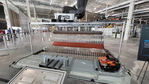
Figure 13: PHS1000 applications: (a) Door ring of Tesla Model Y (SOP 2020)B-79,A-84; (b) Door ring of Voyah Dream (SOP 2022)H-70.
Whereas the microstructure of PHS with a targeted strength of 1500 MPa is martensite, the microstructure of PQS grades contain a combination of ferrite, martensite, and bainite. This indicates that these sections require different thermal profiles.
A publication from 2023 compares the effects of two thermal profiles on the properties of a PQS grade with a mating PHS 1500 grade, as indicated in Table 5. There is little effect on the PHS 1500 properties, but the second profile shows better ductility and a smaller thickness of the Al-Si alloy layer – both of which are preferred.L-74
Table 5: Performance comparison of two processes.L-74
Process
HC370 / 550HS + AS
HC950 / 1300HS + AS
Yield Strength
(MPa)
Tensile Strength
(MPa)
Elongation
(%)
Al-Si Layer Thickness
(µm)
Yield Strength
(MPa)
Tensile Strength
(MPa)
Elongation
(%)
Al-Si Layer Thickness
(µm)
1
509
640
14.00
14
1189
1500
6.74
18
2
365
606
24.72
8
1180
1492
7.72
8
PHS Grades over 1500 MPa
The most commonly used press hardening steels have 1500 MPa tensile strength, but are not the only optionsR-11, with 4 levels between 1700 and 2000 MPa tensile strength available or in development as shown in Figure 14. Hydrogen induced cracking (HIC) and weldability problems limit widespread use in automotive applications, with studies underway to develop practices which minimize or eliminate these limitations.
Figure 14: PHS grades over 1500 MPa tensile strength, compared with the common PHS1500 (re-created after Citations B-18, W-28, Z-7, L-30, L-28, B-14, O-15).
Mazda Motor Corporation was the first vehicle manufacturer to use higher strength boron steels, with the 2011 CX-5 using 1,800MPa tensile strength reinforcements in front and rear bumpers, Figure 15. According to Mazda, the new material saved 4.8 kg per vehicle. The chemistry of the steel is Nb modified 30MnB5.H-33, M-28Figure 16 shows the comparison of bumper beams with PHS1500 and PHS1800. With the higher strength material, it was possible to save 12.5% weight with equal performance.H-33
Figure 15: Bumper beam reinforcements of Mazda CX-5 (SOP 2011) are the first automotive applications of higher strength (>1500 MPa) press hardening steels.M-28
Figure 16: Performance comparison of bumper beams with PHS1500 and PHS1800 (re-created after H-33).
PHS 1800 is also used in the 2022 Genesis Electrified G80 (G80EV) and the new G90, both from Hyundai Motor. A specialized method lowering the heating furnace temperature by more than 50℃ limits the penetration of hydrogen into the blanks, minimizing the risk of hydrogen embrittlement. L-64.
MBW 1900 is the commercial name for a press hardening steel with 1900 MPa tensile strength. An MBW 1900 B-pillar with correct properties can save 22% weight compared to 590DP and yet may cost 9% less than the original Dual-Phase design.H-34 Ford had also demonstrated that by using MBW 1900 instead of PHS 1500, a further 15% weight could be saved.L-30 Since 2019, VW’s electric vehicle ID.3 has two seat crossbeams made of MBW 1900 steel, as seen in Figure 15.L-31 The components are part of MEB platform (Modularer E-Antriebs-Baukasten – modular electric-drive toolkit) and may be used in other VW Group EVs. MBW 1900 can be ordered as uncoated or AS Pro coated (Aluminum-Silicon with Magnesium).T-50
Figure 17: Underbody of VW ID3 (part of MEB platform).L-31
USIBOR 2000 is the commercial name given to a steel grade similar to 37MnB4 with an AlSi (AS) coating. Here, it will be described as PHS2000+AS.. Final properties are expected only after paint baking cycle, and the parts made with this grade may be brittle before paint bake.B-32 In June 2020, Chinese Great Wall Motors started using PHS2000+AS in the Haval H6 SUV.V-12
Since 2023, PHS2000+AS has been used in the A-pillar of Stellantis’ Maserati Grecale SUV. The design allowed downgauging from 1.4 mm PHS1500 to 1.3 mm PHS2000 with comparable crash performance. This weight savings corresponds to 0.8 kg per car. B-80 In late 2023, Toyota introduced the 2nd generation C-HR. This vehicle has a 2 GPa B-pillar with no additional reinforcement. The previous generation had PHS1500 B-pillar with a secondary reinforcement also from PHS1500. The new design not only saved 3.5 kg per vehicle, but also saved cost.A-83See Figure 18 for these applications. PHS2000+AS is also used as a patch in the door ring of Voyah Dream, as pictured in Figure 13b.H-70
Figure 18: PHS2000+AS applications: (a) A-pillar of Maserati GrecaleB-80 and (b) B-pillar of Toyota C-HR.D-45
HPF 2000, another commercial name, is used in a number of component-based examples, and also in the Renault EOLAB concept car.L-28, R-12 An 1800 MPa grade is under development.P-22 Docol PHS 1800, a commercial grade approximating 30MnB5, has been in production, with Docol PHS 2000 in development.S-66 PHS-ultraform 2000, a commercial name for a Zn (GI) coated blank, is suited for the indirect process.V-11
General Motors China, together with several still mills across the country, have developed two new PHS grades: PHS 1700 (20MnCr) and PHS2000 (34MnBV). 20MnCr uses Cr alloying to improve hardenability and oxidation resistance. This grade can be hot formed without a coating, and thus named as coating free PHS (CFPHS). The furnace has to be conditioned with N2 gas. The final part has high corrosion resistance, approximately 9% total elongation (see Figure 12) and high bendability (see Table 4). 34MnBV on the other hand, has a thin AlSi coating (20g/m2 on each side). Compared with the typical thickness of AlSi coatings (30 to 75 g/m2 on each side), thinner coatings are preferred for bendability (see Table 6).W-28More information about these oxidation resistant PHS grades, as well as a 1200 MPa version intended for applications benefiting from enhanced crash energy absorption, can be found in Citation L-60.
A research team, including Volkswagen Group Innovation, have recently developed 37SiB6 steel. They named the grade as SIBORA (Silicon – Boron alloyed steel with Retained Austenite). The grade when hot stamped has a yield strength of approximately 1600 MPa and a tensile strength of 2050 MPa. The microstructure has 3-5% retained austenite, giving it a very high total elongation of 10% (A80, measured on an ISO Type 2, 20×80 tensile specimen). The research team also developed a process called BQP, Bainitizing, Quenching and Partitioning. With this method, several strength-ductility levels can be achieved from the same alloy.O-15 BQP process is explained in the next section under Single Alloy Concepts.
Figure 19: 37SiB6, also known as SIBORA, before and after hot stamping (re-created after O-15).
Single Alloy Concepts
In 2021, a research group from China came up with the Uni-Steel proposal, where the whole car body can be built by using a single alloy concept. The material is similar to 22MnB5 but has higher Cr and Si content, and some Nb alloying. When hot stamped, the material would have a yield strength of 1400 MPa (typical) and tensile strength of 1600 MPa (thus named as PHS1600 in Figure 20a). When different heat treatments are applied, the material can be as soft as 420 MPa yield / 600 MPa tensile. This is named as HSLA in Figure 20a. The authors specified 6 different process routes, ending up 6 different material specs as shown in Figure 20. There was also a car body design made of single alloy, different strength levels, as shown in Figure 20c.L-68
Figure 20: Uni-Steel concept: (a) Different variants, b) their engineering stress-strain curves, (c) a concept BIW design using these variants (re-created after L-68).
SIBORA, or 37SiB6, can also be processed using a Bainitizing, Quenching and Partitioning (BQP) process to generate different variants. In the BQP process, the sheet metal is first austenitized around 930°C and then rapidly cooled to bainitizing temperature, between 360 and 460°C, as seen in Figure 21a. The bainitizing temperature and time affect tensile properties. By tailoring both variables, tensile strength can be altered between 1150 and 2050 MPa, total elongation can be altered between 19% and 9%, Figure 21b.O-15
Figure 21: (a) Schematic time-temperature curve of BQP process, (b) several variants of SIBORA (37SiB6) using hot stamping and BQP process routes (both re-created after L-15).
Other Steels for Press Hardening Process
In recent years, many new steel grades are under evaluation for use with the press hardening process. Few, if any, have reached mass production, and are instead in the research and development phase. These grades include:
Studies of press hardening of stainless steels primarily focus on martensitic grades (i.e., AISI SS400 series).M-36, H-42, B-40, M-37, F-30 As seen in Figure 22, martensitic stainless steels may have higher formability at elevated temperatures, compared to PHS1500 (22MnB5). Other advantages of stainless steels are:
No scale formation at high temperatures, no controlled atmosphere is required in the furnaceL-70
better corrosion resistance of the final partM-37,
allow higher heating rates (i.e., induction heating), since the blanks are uncoated (no rules for coating diffusion) F-30,L-70
possibility of air hardening – allowing the multi-step process — as seen in Figure 23aH-42,
Disadvantages include (a) higher material cost, (b) higher furnace temperature (up to around 1050-1150 °C – see Table 6), and (c) high Cr content would significantly reduce weldability.M-37, F-30 As of 2025, there are only two commercially available stainless steel grades specifically developed for press hardening process.A-85At least one more stainless steel maker have also developed a grade for hot stamping (420C), however, it was not listed in their commercial offerings, as of 2025.
Figure 22: Tensile strength and total elongation variation with temperature of (a) PHS1500 = 22MnB5M-38 and (b) martensitic stainless steel.M-36
Figure 23: (a) Critical cooling rate comparison of 22MnB5 and AISI SS410 (re-created after Citation H-42, (b) Room temperature forming limit curve comparison of DP600 and modified AISI SS410 (re-created after Citation M-37.
Final mechanical properties of stainless steels after press hardening process are typically superior to 22MnB5, in terms of elongation and energy absorbing capacity. Figure 24 illustrates engineering stress-strain curves of the two commercially available grades (1.6065 and 1.4064), and compares them with the 22MnB5 and a duplex stainless steel (Austenite + Martensite after press hardening and tempering). The duplex grade was also developed by a stainless steel maker, but is still not commercially available. These grades may also have bake hardening effect, abbreviated as BH0, as there will be no cold deformation.B-40, M-37, F-30
Figure 24: Engineering Stress-Strain curves of press hardened stainless steels, compared with 22MnB5 (re-created after Citations B-40, M-37, F-30, B-41).
Table 6: Summary of mechanical properties of press hardenable stainless steel grades. Typical values are indicated with “~”. (Table generated from Citations B-40, M-37, F-30, and D-46.)
Terminology
Furnace
Temperature
(Theat)
[°C]
Secondary
Tempering
Proof Strength
(Rp0.2)
[MPa]
Tensile Strength
(Rm or σUTS)
[MPa]
Elongation
(A*)
[%]
VDA Bending
Angle **
(α) [°]
1.4034
420C
1150
400°C, 5 min.
1100-1300
1700-1850
12-16
–
1.4003
410L
950
–
~830
~1020
~7
–
1.4021
420
1030
–
~1125
~1750
~5
–
1.4021
420
1030
600°C, 10 min.
~930
~1090
~9
–
1.6065
Modified 410
1050
–
~1200
~1600
≥7
~70
1.6065
Modified 410
950
–
~870
~1130
≥10
~100
** VDA Bending angle may depend on thickness and method of measurement (α0 or αM)
Other than these, there is also a study where 27MnB5 was cladded with AISI 304 on both top and bottom. This study is explained in detail in Composite Steels section.
Medium-Mn Steels
Medium-Mn steels typically contain 3 to 12 weight-% manganese alloying.D-27, H-30, S-80, R-16, K-35 Although these steels were originally designed for cold stamping applications, there are numerous studies related to using them in the press hardening process as well.H-30 Several advantages of medium-Mn steels in press hardening are:
Austenitization temperature may be significantly lower than compared to 22MnB5, as indicated in Figure 19.H-30, S-80 Thus, using medium-Mn steels may save energy in heating process.M-39 Lower heating temperature may also help reducing the liquid-metal embrittlement risk of Zn-coated blanks. It also may reduce oxidation and decarburization of uncoated blanks.S-80
Martensitic transformation can occur at low cooling rates. Simpler dies could be used with less or no cooling channels. In some grades, air hardening may be possible. Thus, multi-step process could be employed.S-80, B-14
Some retained austenite may be present at the final part, which can enhance the elongation, through the TRIP effect. This, in turn, improves toughness significantly.S-80, B-14
Figure 25: Effect of Mn content on equilibrium transformation temperatures (re-created after Citations H-30, B-14).
The change in transformation temperatures with Mn-alloying was calculated using ThermoCalc software.H-30 As seen in Figure 25, as Mn alloying is increased, austenitization temperatures are lowered.H-30 For typical 22MnB5 stamping containing 1.1 to 1.5 % Mn, furnace temperature is typically set at 930 °C in mass production. The multi-step material 22MnSiB9-5 has slightly higher Mn levels (2.0 to 2.4 %), so the furnace temperature could be reduced to 890 °C. As also indicated in Table 6, the furnace temperature could be further lowered to 650°C in hot forming of medium-Mn steels.
A study in the EU showed that if the maximum furnace temperature is 930 °C, which is common for 22MnB5, natural gas consumption will be around 32 m3/hr. In the study, two new medium-Mn steels were developed, one with 3 wt.% Mn and the other with 5 wt% Mn. These grades had lower austenitization temperature, and the maximum furnace set temperature could be reduced to 808 °C and 785 °C, respectively. Experimental data shows that at 808 °C natural gas consumption was reduced to 19 m3/hr, and at 785 °C to 17 m3/hr.M-39 In Figure 26, experimental data is plotted with a curve fit. Based on this model, it was estimated that by using 22MnSiB9-5, furnace gas consumption may be reduced by 15%.
Figure 26: Effect of maximum furnace set temperature (at the highest temperature furnace zone) on natural gas consumption (raw data from Citation M-39).
Lower heating temperature of medium-Mn steels may also help reducing the liquid-metal embrittlement risk of Zn-coated blanks. It also may reduce oxidation and decarburization of uncoated blanks.S-80
Medium-Mn steels may have high yield-point elongation (YPE), with reports of more than 5% after hot stamping. Mechanical properties may be sensitive to small changes in temperature profile. As seen in Figure 27, all studies with medium-Mn steel have a unique stress-strain curve after press hardening. This can be explained by:
differences in the chemistry,
thermomechanical history of the sheet prior to hot stamping,
heating rate, heating temperature (see Figure 28), and soaking time, and
secondary heat treatments such as quenching and partitioning.W-41
In a recent study, various heating temperatures were examined. As seen in Figure 28, both the stress-strain behavior and the phase fractions change significantly with heating temperature.W-42
Figure 27: Engineering Stress-Strain curves of several press hardened medium-Mn steels, compared with 22MnB5. See Table 7 for an explanation of each tested material (re-created after Citations S-80,L-37, W-30, L-38).
Figure 28: Engineering stress-strain curves of 4% Mn steel, heated to different temperature (760. 800 and 840°C). Phase fractions are also affected by the heating temperature (re-created after W-42).
Table 7: Summary of mechanical properties of press hardenable Medium-Mn grades shown in Figure 27.
Typical values are indicated with “~”.
Toughness is calculated as the area under the engineering stress-strain curve.
Items 4 and 5 also were annealed at different temperatures and therefore have different thermomechanical history.
Note that these grades are not commercially available.
Based on Citations L-38, W-30, L-37, S-80, and W-42.
TriBond ® is the name given to a family of steel composites.T-32 Here, three slabs (one core material (60 to 80% of the thickness) and two cladding layers) are surface prepared, stacked on top of each other, and welded around the edges. The stack is hot rolled to thickness. Cold rolling could also be applied. Initially, TriBond ® was designed for wear-resistant cladding and ductile core materials.
The original design was optimized for hot stamping.B-14 The core material, where bending strains are lower than the outer layers, is made from generic 22MnB5 (PHS1500). Outer layers are made with PQS450. The stack is cold rolled, annealed and AlSi coated.Z-9 Two grades are developed, differing by the thickness distribution between the layers, as shown in Figure 29.R-14
Figure 29: Sample microsections of the conventional hot stamping grade PHS1500+AS, the high strength composite Tribond® 1400 and the high energy absorbing composite Tribond® 1200. The Tribond® 1200 microsection is experimental and is taken from Citation R-14. The other two images are renditions created by the author for explanation purposes. (re-created after Citations R-14, R-15)
Total elongation of the composite steel is not improved, compared to PHS1500, as shown in Figure 30. The main advantage of the composite steels is their higher bendability, as seen in Table 8. Crashboxes, front and rear rails, seat crossmembers and similar components experience axial crush loading in the event of a crash. In axial crush, Tribond® 1200 saved 15% weight compared to DP780 (CR440Y780T-DP). The bending loading mode effects B-pillars, bumper beams, rocker (sill) reinforcements, side impact door beams, and similar components during a crash. In this bending mode, Tribond® 1400 saved 8 to 10% weight compared to regular PHS1500. Lightweighting cost with Tribond® 1400 was calculated as €1.50/kgsaved.G-37, P-26
Figure 30: Engineering Stress-Strain curves of core layer, outer layer and the composite steel (re-created after Citation P-26).
In 2021, two German universities developed a similar composite steel, this time the core was 27MnCrB5-2 with stainless steel 1.4301 (AISI 304) claddings at the top and bottom. The details of the study is summarized in Table 8.K-63
Table 8: Summary of composite steels and comparison with conventional PHS and PQS grades.
Typical values are indicated with “~”. (Table re-created after Citations B-14 and K-63.)
Grade
Composition
through
thickness
Proof Strength
(Rp0.2)
[MPa]
Tensile Strength
(Rm or σUTS)
[MPa]
Elongation
(A80)
[%]
Bending
angle (α) [°]
PQS450
100% PQS450
~400
~550
~17
140-155
Tribond ® 1200
20% PQS450
60% PHS1500
20% PQS450
≥730
≥1100
≥5
≥135
Tribond ® 1400
10% PQS450
80% PHS1500
10% PQS450
≥890
≥1300
≥5
≥75
PHS1500
100% PHS1500
≥1000
≥1400
≥5
≥55
AISI304
100% AISI 304
~300
~640
–
–
Composite Steel
12.5% AISI 304
75% 27MnCrB5-2
12.5% AISI304
~820
1300
–
–
27MnCrB5-2
100% ‘7MnCrB5-2
~1020
~1500
–
–
* Graphs in this article are for information purposes only. Production materials may have different curves. Consult the Certified Mill Test Report and/or characterize your current material with an appropriate test (such as a tensile, bending, hole expansion, or crash test) test to get the material data pertaining to your current stock.
For more information on Press Hardened Steels, see these pages:
Key materials characteristics for formed parts include strength, thickness, and corrosion protection. Tailored products provide opportunities to place these attributes where they are most needed for part function, and remove weight that does not contribute to part performance.
Welded Tailored Blanks (Tailor Welded Blanks)
Welded tailored blanks are a type of tailored product, as are patchwork blanks, tailor welded coils, tailor rolled coils, tailor rolled tubes and tailor welded tubes.
Laser welding is the most common approach to creating these products, but other options like resistance mash seam welding are possible. Mash seam welding requires that the blanks overlap, which adds mass. The heat affected zone (HAZ) for mash seam welds is considerably larger than that of laser welds. Compared with laser welding, the temperature reached when resistance mash seam welding is lower. This may improve formability due to reduced martensite formation, but the larger HAZ and thicker joint may negate this benefit. Non-linear welds are more challenging to produce with the mash seam approach. Welded Tailored Blanks refers to blanks made via either laser welding or mash seam welding. The following discussion centers on blanks and coils joined by lasers.
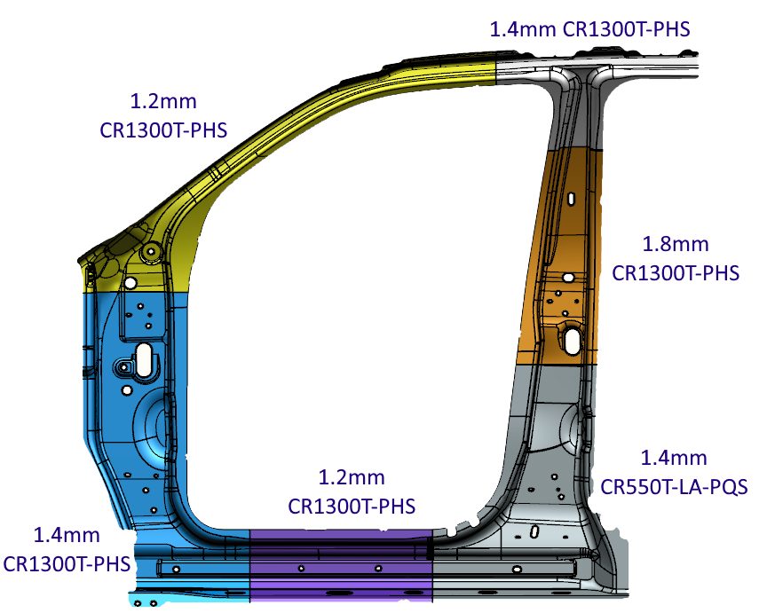
Butt-welding two or more flat sheets into a single blank creates a laser welded tailored blank (LWTB), also known as a tailor welded blank or laser welded blank (LWB). Steel grades and thickness may be (and usually are) different in the component sheets. Corrosion protection strategies may be different on each component of the welded blank. “Sub blanks” is another name for these component sheets.
Figure 1 shows a laser welded door ring with multiple grades and thicknesses. This technology allows for a reduction in panel thickness in non-critical areas, thus contributing to an overall mass reduction of the part. The lower strength product in the bottom section of the B-Pillar helps dissipate the crash energy in the event of a side impact, playing a key role in crash energy management.
Figure 1: Six-piece Laser Welded Tailored Blank with multiple grades and thickness.R-3
Patchwork Blank
An alternate approach to a laser welded tailored blank involves the creation of what is known as a patchwork blank, consisting of two or more blanks potentially having different thickness or grades. The unique characteristic is that the blanks are placed one on top of the other and (typically) spot welded together while still flat. The patched blank requires only one stamping operation, eliminating the need to join them after forming the components separately. This approach is satisfactory for both cold stamping and hot stamping. The correct number of spot-welds is important in terms of cost and safety. Furthermore, if the components shift relative to one another during the forming operation, the spot welds may shear. There is excellent fit between both parts after forming, allowing for easy application of additional spot welds if needed. Part size, the number and location of reinforcements, and available infrastructure are among the key considerations in deciding between a laser welded or patch blank approach. For example, patchwork blanks may be preferred if the reinforced area is relatively small with complex contours or located within the boundaries of the main blank.
Tailor Welded Coils
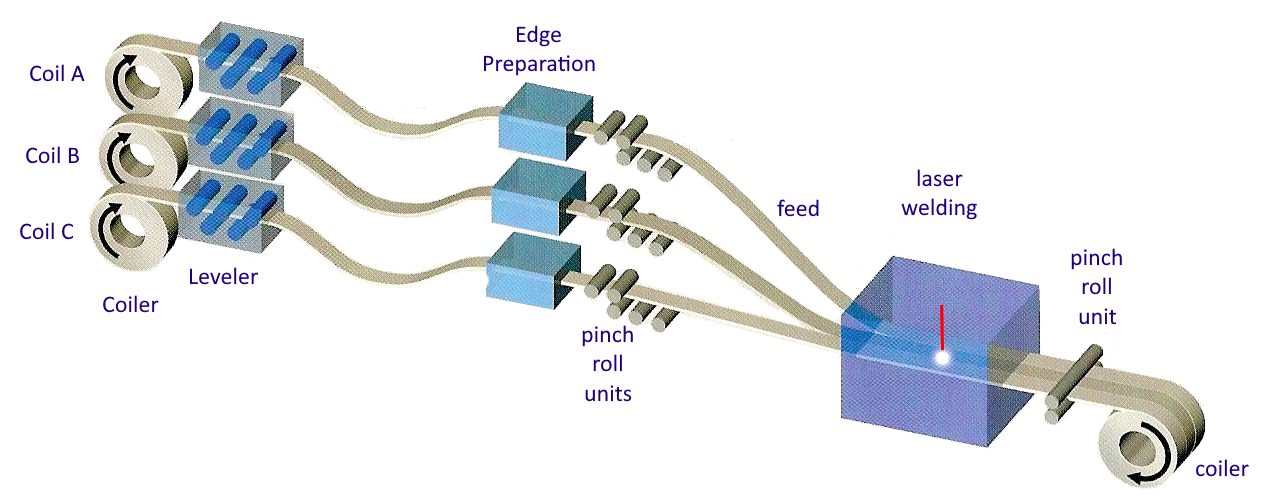
Rather than building blanks from individual components, a similar approach is to join entire coils together, edge to edge. These tailor welded coils (Figure 2) are used in coil-fed processes such as blanking, progressive die stamping, transfer press stamping, and roll forming operations. The basic process takes separate coils, prepares their edges for contiguous joining, and laser welds these together into one master coil. The new strip is either directly blanked or re-coiled for future blanking or use as feedstock for a continuous coil-fed stamping or roll forming line (Figure 3). Variations in strength, thickness, and coating occur across the width.
Figure 2: Production Process of Tailor Welded Coils.S-28
Figure 3: General usage of Tailor Welded Coils.S-28
Tailor Rolled Coils
Whereas tailor welded coils can vary in properties across the coil width, tailor rolled coils have variable thickness down the length of the coil. Production facilities for tailor rolled coils vary the gap between the rolls used for thickness reduction, allowing for different strip thicknesses in the direction of rolling (Figure 4). Accurate measuring and feedback control technology guarantees the strip thickness tolerances. A significant advantage to this approach results from the transition from one thickness to another with no joints or discontinuities, providing an efficient load path without stress risers. A tailor rolled coil can be either used for blanking operations (for stamping or tubular blanks), or as feedstock into a roll forming line.
Figure 4: Tailor Rolled Coils vary in thickness down the length of the coil.Z-5
After cold rolling to achieve the targeted thickness variation, coils are annealed to reset the mechanical properties. Tensile properties can be uniform in the blank, with only the thickness varying. Tailored properties are generated by adjusting the incoming coil thickness and the associated thickness reductions, leading to different degrees of recrystallization occurring in the annealing step.Z-14TRBs used in press hardening do not need to be annealed first, and tailored properties can be produced with the appropriate PHS process.
Tailor Rolled Tubes
Tailor rolled coils are the feedstock to produce variable thickness tailor rolled tubes.
Tailor Welded Tubes
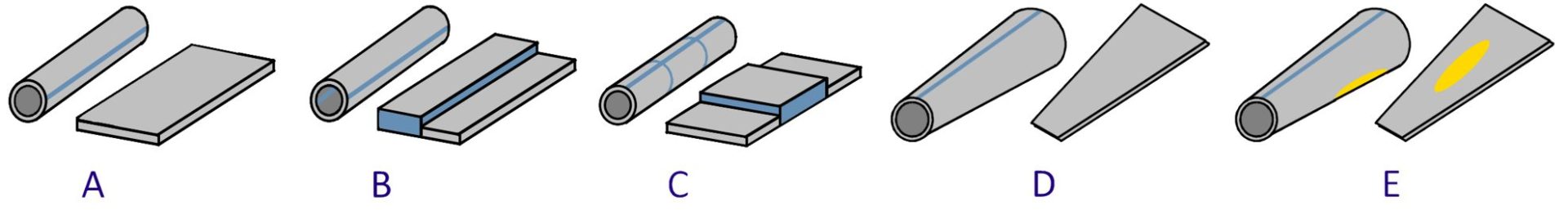
Conventional tube production involves roll forming strips to the desired shape and welding the free ends together to create a closed section. A tailor welded tube production process allows the designer to create complex variations in shape, thickness, strength, and coating (Figure 5)
Figure 5: Tailored tube production allows for differing thickness and strength within the same tube. A) 1-piece cylindrical tube with monolithic properties; B and C) 2-piece tailored tube with property variation down the length of the tube; D) 1-piece conical tube; E) 2-piece conical tube with a patchwork blank.
With hydroforming technology, the next step in tubular components is to bring the sheet metal into a shape closer to the design of the final component without losing tailored blank features (Figure 6).
Figure 6: Mechanical properties of tailored tubes are close to the original metal properties in the sheet condition. Hydroforming changes the properties based on the local deformation.G-8
Hydroformed conical tailored tubes offer automotive body engineers an additional approach to crash energy management while achieving a lightweight design. In frontal crash and side impacts the load paths have a key importance on the body design as they have a major bearing on the configuration of the structural members and joints. Figure 7 shows an example of a front-rail hydroformed prototype. The conical tailored tubes for this purpose take advantage of the high work hardening potential of TRIP steel.
Figure 7: Front-rail prototype based on a conical tube having 40 mm end to end difference in diameter.F-3
Another approach to create a tube with differential wall thickness is by ironing the inner surface.
One method to achieve this is to fix one end of the tube with a stopper, and expand that tube by pushing the punch (Figure 8) into the other end. Next, the stopper is removed and, with the part expanded in the first process engaged with the die, the punch is pushed in to iron the inner tube surface which reduces its wall thickness. The punch is pushed in until the length of the ironed part has reached the targeted value. Finally, the punch is retracted and removed. As a result of these forming processes, a tube with differential wall thickness consisting of a longitudinal expanded part (thick), ironed part (thin), and unprocessed part (thick) can be obtained.K-67 Among the factors contributing to forming success are the interaction of the punch design, including the length of the parallel section (LP) and semiangle (αP), and the clearance between the punch and die (CP). The length of the parallel section and the semiangle have been shown to have a significant effect on the forming load, but the clearance did not.K-67 The punch with larger LP, or the punch with smaller αP or smaller CP, results in improved formability. This happens because steel tube slipping does not occur even at small friction differences between the tube-punch and tube-die interfaces (Δµ) due to the forces being in equilibrium.K-67 Finite element modeling of these parameters, as well as experimental verification, can be found in this citation as well.
Figure 8: Punch shape to facilitate production of tailored tube, according to Citation K-67.
Benefits of Tailored Products in Automotive Body Construction
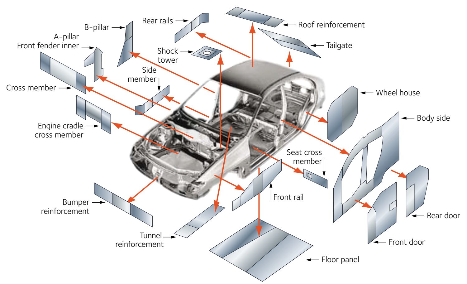
Figure 9 highlights some of the areas within the body structure where companies have considered transitioning to welded tailored blanks. Other tailored products may be suitable in other areas.
Figure 9: Applications suited for welded tailored blanks.A-31
Tailored products offer numerous advantages over the conventional approach involving the stamping and assembly of individual monolithic blanks which have a single grade, thickness, and coating, including:
Improved materials utilization
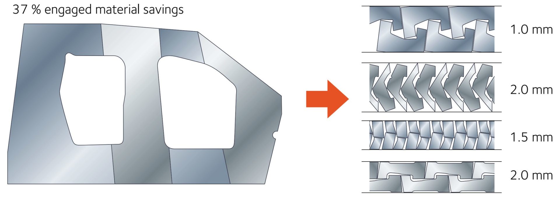
Certain parts, like door rings (Figure 1), window frames, and door inner panels, have large cutout areas contributing to engineered scrap. Converting these to welded tailored blanks allows for optimized nesting of the individual components. Figure 10 presents an example of optimized nesting associated with body side aperture designs using a tailor welded blank. Reduced blank width requirements may allow for additional suppliers or use of master coils yielding slit mults. In the other extreme, blank dimensions larger than rolling mill capabilities are now feasible.
Elimination of reinforcement parts and reduced manufacturing infrastructure requirements
In areas needing additional thickness for stiffness or crash performance, conventional approaches require stamping both the primary part and an additional smaller reinforcement and then spot welding the two parts together. The tailored product directly incorporates the required strength and thickness. Compared with a tailored product, the conventional approach requires twice the stamping time and dunnage, creates inventory, and adds the spot welding operation. Tolerance and fit-up issues appear when joining two formed parts, since their individual springback characteristics must be accommodated.
Part consolidation
Similar to the benefits of eliminating reinforcements, tailored products may combine the function of what would otherwise be multiple distinct parts which would need to be joined.
Weight savings
Conventional approaches to body-in-white construction requires individual parts to have flat weld flanges to facilitate spot welding. Combining multiple parts into a tailored product removes the need for weld flanges, and their associated weight.
Improved NVH, safety, and build quality
Joining formed parts is more challenging than joining flat blanks first and then stamping. Tailored products have better dimensional integrity. Elimination of spot welds leads to a reduction in Noise, Vibration, and Harshness (NVH). A continuous weld line in tailored products means a more efficient load path.
Enhanced engineering flexibility
Using tailored products provides the ability to add sectional strength in precise locations to optimize body structure performance.
Easily integrated with advanced manufacturing technologies for additional savings
Tailored products incorporated into hot stamping or hydroforming applications magnify the advantages described here, and open up additional benefits.
Edge Quality of Component Blanks Used to Create the Welded Blank
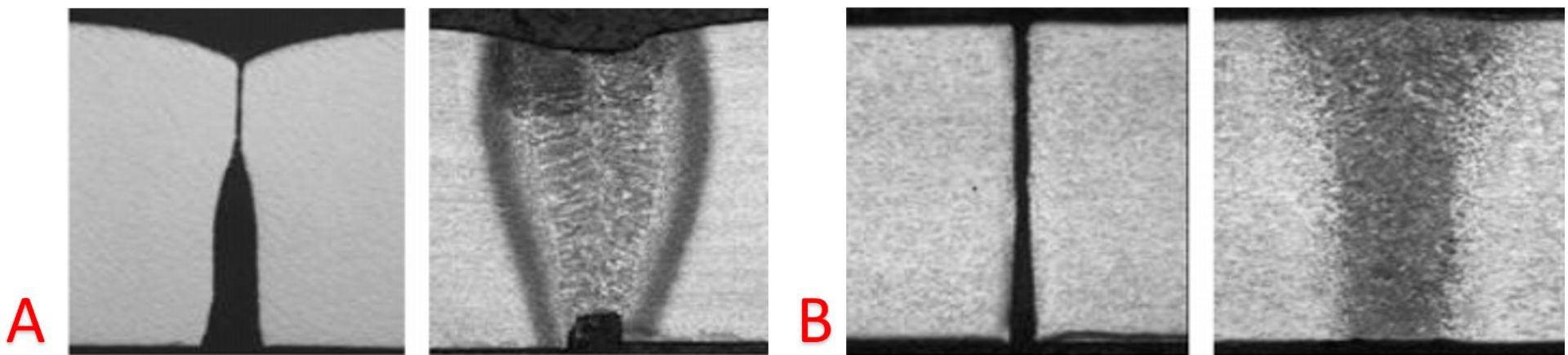
Minimal burr, maximized sheared edge stretchability, and maximized tool life are characteristics of good sheared edge quality in conventional blanking operations. When creating sub-blanks for assembly into a laser welded tailored blank, there is an additional critical characteristic: squared edges with high straightness are a prerequisite to avoid local gaps between the blank edges causing undercut in the weld bead and the associated loss of mechanical properties (Figure 11). Conventional shearing operations produce the edge seen in Figure 11a. Precision die blanking with tight clearances, as well as laser blanking, produce edges suitable for the blank welding operation (Figure 11b). Another option is to use a conventional shearing approach to produce a slightly oversize blank, and then use precision shears as the first step in the laser welding line. The advantage to this approach minimizes the impact of edge damage which might occur during transportation.
Figure 11: Edge condition and welding result. A) Poor edge resulting in increased residual butt gap and weld undercut; B) Optimum squared edge by precision die blanking or laser welding resulting in flush weld surfaces.S-29
Forming analysis of Welded Blanks
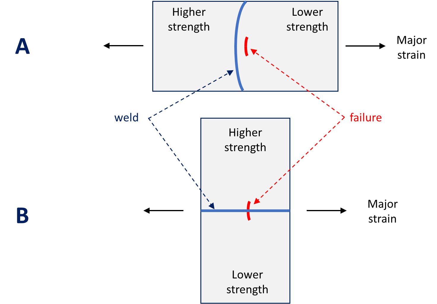
The weld joint and adjacent heat affected zone complicates the forming analysis of welded blanks. There are generally two scenarios that occur: failure perpendicular to the weld and failure parallel to the weld (Figure 12).
Figure 12: Major strain axis relative to weld line orientation. A) Weld line is perpendicular to the major strain axis; B) Weld line is parallel to the major strain axis.
Consider the scenario in Figure 12A, where the major strain is perpendicular to the weld line orientation. Failure occurs parallel to the weld in the lower strength, more ductile material. The restraining force provided by the higher strength material results in the weld line shifting towards that side.
With the weld seam moving towards the thicker and stronger metal, deformation occurs in thinner and weaker metal. The movement of the weld seam during stamping requires that a blankholder design with appropriate clearances so the welds can move through the blankholder during the drawing process. The punch-cavity clearances must allow for movement as well – otherwise a pinch-point is created and metal flow stops. These clearances are necessary for movement of the heavier gauge metal and the welds, but can also be a source of wrinkling on the lighter gauge side due to the lack of hold-down force in this area. Also, the potential exists for die wear in the locations in contact with weld seam. To counter the weld line motion to the higher strength side, consider allowing greater material flow from that side of the weld through a less severe draw bead design, reduced blankholder pressure or modified blank outline. These strategies help minimize the risk of this type of split.
Now consider the scenario in Figure 12B, where the major strain is parallel to the weld line orientation. Here, fracture occurs perpendicular to the weld line – typically within the weld itself – due to the poorer mechanical properties of the weld with respect to the base material. To avoid splits in the weld, orient the weld away from the major strain direction and away from areas with high strain concentration.
Use of Advanced High Strength Steels in Laser Welded Tailored Products
As sub-blanks are welded together to create the main blank, the beginning or ending of each of the weld lines are not in a steady state condition. As such, the start or stop action of the welding may create a stress riser. After the main blank is built-up, a scalloped cut can remove the affected areas so that only sections of uniform edge quality are formed in subsequent operations.
Laser welding is a high energy density process that focuses the heat in a very localized region as the laser travels at a high speed. This results in a narrow heat affected zone and the rapid quenching leads to the formation of a high-hardness martensite. Increased welding speeds generally require higher energy intensity at the weld which increases peak hardness.
Different welding parameters must be used for advanced high strength steels due to the presence of martensite in the base metal. The microstructure in the heat affected zone is a function of the local time/temperature profile, which changes with distance away from the weld as well as with the composition of the alloy in question. Laser welding some AHSS grades results in tempered martensite in the heat affected zone, leading to a locally softened region. Crash modeling should incorporate the influence of the softened region, which may help dissipate a portion of the crash energy.
However, this softened region creates an area for high strain concentration, leading to premature failure in martensite-containing AHSS grades. Higher strength dual phase steels have more martensite than lower strength dual phase grades, and therefore are more likely to generate HAZ soft zones and reduced formability when used in laser welded blanks. CP and TRIP steels have a lower incidence of HAZ soft zones due to higher alloying content. More information about laser welding is found here.
Blank Stacking, Destacking, and Feeding Problems
Depending on the thickness differences between the component blanks and their relative sizes, embossed dimples on the thinner gauge side can balance the thickness difference and to allow stable coil winding (in the case of tailor welded coil production) or stacking as they are blanked onto a lift. The stack weight and banding of the pallets may contribute to collapsing the dimples, so some companies choose to minimize the stack height.
Automatic destackers and feeders typically require uniform blanks and stacks for trouble-free operation. Dimples and cutouts may interfere with proper operation of overhead vacuum cups or magnetic belts. Moving or deactivating Vacuum cups may be necessary. Dimples should either be outside of the magnetic belt area or have their form away from the belt. Dimples may be a problem for some in-line blank washers and die-lube roll coaters.
Press and Tooling Considerations
When there is a large thickness difference within the component blanks, press tonnage and balance can be a problem. Press tonnage monitors are essential for this type of part, not only for protection of the press equipment, but also for good process control. If press balance is a problem, the tonnage monitors will indicate where the problem is. Supplemental balance devices in the die, such as nitrogen cylinders, may be appropriate, or the stamping may need to move to a larger press.
Tailored products often contain sub-blanks of mixed strength and thickness. The chosen die process must reflect those differences, and account for changes in side-wall curl, springback and drawability characteristics across the part. Mild steel can usually be formed with high strength steel die processes, but high strength steel will not always form satisfactorily with conventional die processes used with mild steels.
Laser-welded blanks (LWBs) allow the combination of different steel grades, thicknesses, and even coating types into a single blank. This results in stamping a single component with the right material in the right place for on-vehicle requirements. This technology allows the consolidation of multiple stampings into a single component.
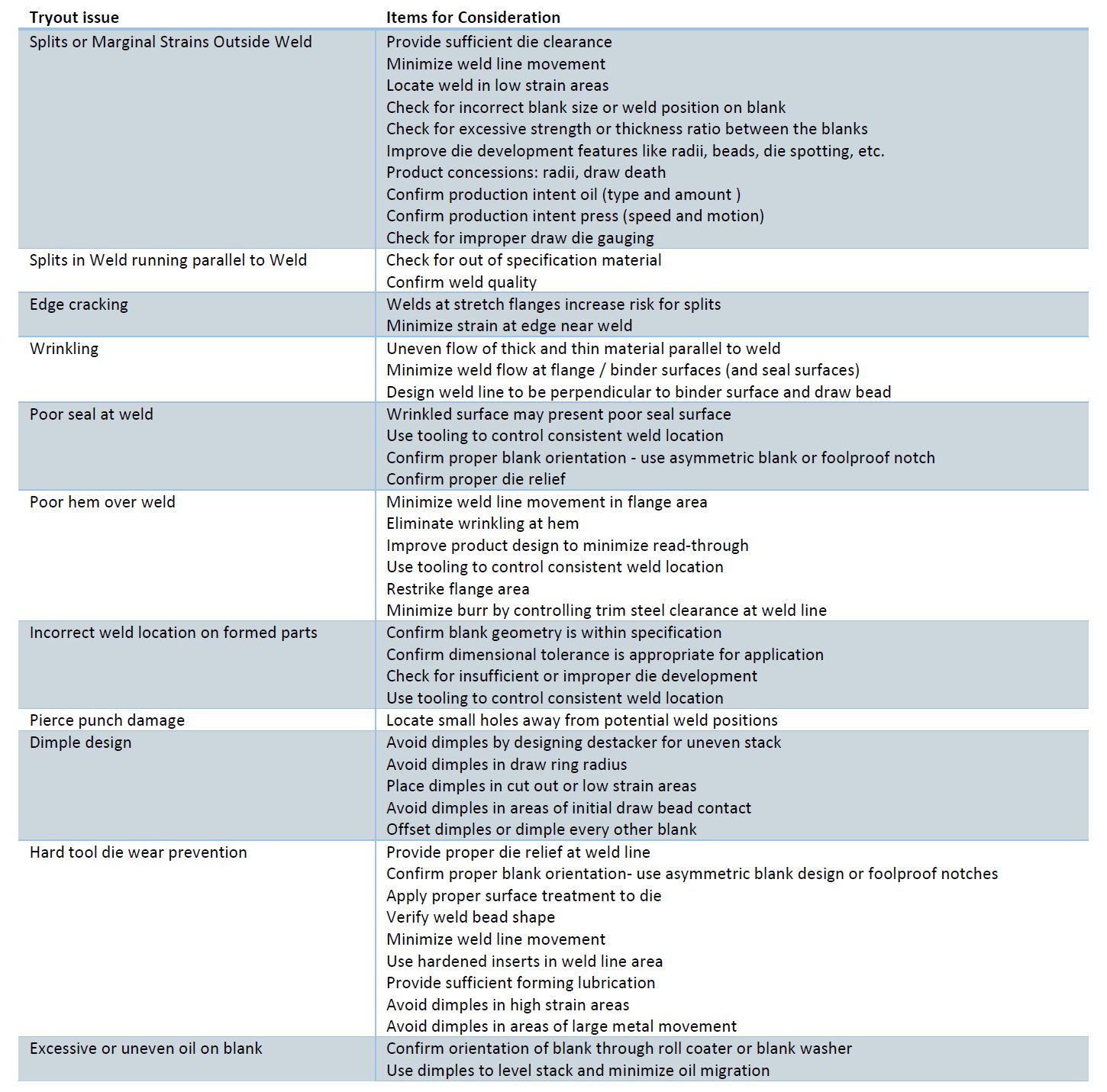
One example is the front door inner. A two-piece design will have an inner panel and a reinforcement in the hinge area. As shown in Figure 13, a laser welded front door inner incorporates a thicker front section in the hinge area and a thinner rear section for the inner panel, providing on-vehicle mass savings. This eliminates the need for additional components, reducing the tooling investment in the program. This also simplifies the assembly process, eliminating the need to spot weld a reinforcement onto the panel.
Figure 13: Front Door Inner Stamped from a Laser Welded Blank
Today, large opportunities exist to consolidate components in a BEV in the battery structure. Design strategies vary from different automakers, including how the enclosure is constructed or how the battery mounts into the vehicle. The battery tray can have over 100 stamped components, including sealing surfaces, structural members, and reinforcementsM-68. As an idea, a battery tray perimeter could be eight pieces, four lateral and longitudinal members, and four corners. The upper and lower covers are two additional stamped components, for a total of ten stampings that make up the sealing structure of the battery tray. On a large BEV truck, that results in over 17m of external sealing surfaces.
Part consolidation in the battery structure provides cost savings in material requirements and reduced investment in required tooling. Another benefit of assembly simplification is improved quality. Fewer components mean fewer sealing surfaces, resulting in less rework in the assembly process, where every battery tray is leak-tested.
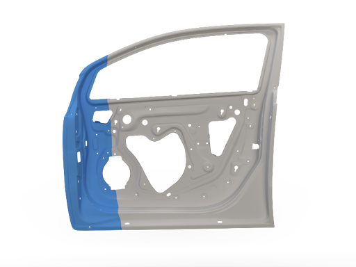
The deep-drawn battery tub is a consolidated lower battery enclosure and perimeter. This can be seen in Figure 14; a three-piece welded blank incorporates a thicker and highly formable material at the ends and in the center section, either a martensitic steel for intrusion protection or a low-cost mild steel. This one-piece deep-drawn tub reduces the number of stampings and sealing surfaces, resulting in a more optimized and efficient design when considered against a multi-piece assembly. In the previous example of a BEV truck, the deep-drawn battery tub would reduce the external sealing surface distance by 40%. To validate this concept, component level simulations of crash, intrusion, and formability were conducted. As well as a physical prototype built that was used for leak and thermal testing Y-14 with the outcomes proving the validity of this concept, as well as developing preliminary design guidelines. Additional work is underway to increase the depth of the draw while minimizing the draft angle on the tub stamping.
Figure 14: Deep Battery Tub Stamped from a Laser Welded Blank
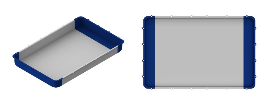
In most BEVs today, the passenger compartment has a floor structure common in an ICE vehicle. However, the BEV also has a top cover on the battery assembly that, in most cases, is the same size as the passenger compartment floor. In execution of part consolidation, the body floor and battery top cover effectively seal the same opening and can be consolidated into one component. An example is shown below, where seat reinforcements found on the vehicle floor are integrated into the battery top cover, and the traditional floor of the vehicle is removed. Advanced high-strength steels are used in different grades and thicknesses. Figure 15 show what the laser welded battery top cover looks like on the assembly.
Figure 15: Battery Top Cover from a Laser Welded Blank
Vehicle assembly can also be radically simplified as front seats are mounted on the battery before being installed in the vehicle as shown in Figure 16, the ergonomics of the assembly operation are improved by increased access inside the passenger compartment through the open floor.
Figure 16: Ergonomics of the Assembly Operation
Cost mitigation is more important than ever before, with reductions in piece cost and investment and assembly costs being important. At the foundation BEVs currently have cost challenges in comparison to their ICE counterparts, however the optimization potential for the architecture remains high, specifically in part consolidation. Unique concepts such as using laser welded blanks for deep-drawn battery tubs and integrated floor/battery top covers are novel approaches to improve challenges faced with existing BEV designs. Laser welded blank applications throughout the body in white and closures remain relevant in BEVs, providing further part consolidation opportunities.
Thanks go to Isaac Luther for his contribution of this case study. Luther is a senior product engineer on the new product development team at TWB Company. TWB Company provides tailor-welded solutions in North America. In this role, Isaac is responsible for application development in vehicle body and frame applications and battery systems. Isaac has a Bachelor of Science in welding engineering from The Ohio State University.


![Figure 13: PHS1000 applications: (left) Door ring of Tesla Model Y (SOP 2020) [Citations B-79 and A-84], (right) Door ring of Voyah Dream (SOP 2022). [Citation H-70].](https://ahssinsights.org/wp-content/uploads/2025/11/PHS-Grade-RevFig-13.svg)


![Figure 28: Engineering stress-strain curves of 4% Mn steel, heated to different temperature (760. 800 and 840°C). Phase fractions are also affected by the heating temperature (re-created after [CITATION 20]).](https://ahssinsights.org/wp-content/uploads/2025/09/PHS-Grades-Figure-28.svg)


![Figure 3: General usage of Tailor Welded Coils [S-28]](https://ahssinsights.org/wp-content/uploads/2020/07/tailor-welded-cole-common-use.jpg)