Manufacturers embrace Advanced High Strength Steels as a cost-effective way to satisfy functional and regulatory requirements. The following are just a few examples where automakers have attributed improved performance and lightweighting due to the use of these advanced steels.
KIA EV9
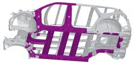
The Kia EV9, Kia’s first three-row electric flagship SUV, is based on the Electric Global Modular Platform (E-GMP).K-59 Kia EV9 won the 2024 North American Utility Vehicle of the Year™ (NACTOY) AwardK-60, and was named a 2024 Top Safety Pick by IIHS, the Insurance Institute for Highway Safety.K-61 Kia deployed hot stamped parts in the passenger safety cage for enhanced passenger protection and crash energy management.K-62

Figure 1: Hot stamped parts increase the average tensile strength in the 2024 Kia EV9K-62
Tesla Cybertruck and Model Y
Much press has been given to the “ultra-hard stainless steel” used on the Cybertruck skin panelsT-46, but there are several high strength and advanced high strength steel parts on the vehicle as well. According to the Cybertruck Collision Repair Manual,T-47 Tesla defines mild steel as having a tensile strength less than 270 MPa. The tensile strength of high strength steels ranges from 300 MPa to 700 MPa. Ultra high strength steels are those with a tensile strength greater than 800 MPa. Figure 2 presents a breakdown of materials used in the body structure.
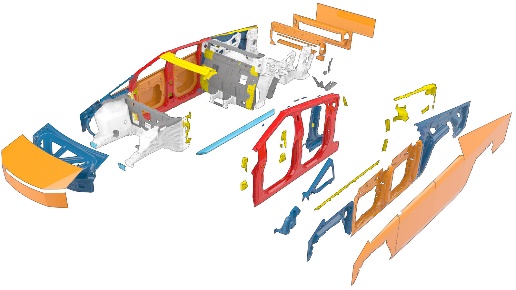
Figure 2: Cybertruck Body Materials. Dark blue = mild steel; yellow = high strength steel; red = ultra high strength steel; orange = stainless steel.T-47
A video by Munro Live with Lars Moravy, Tesla’s Head of Vehicle Engineering, shows that the Cybertruck body side inner is formed from a laser welded press hardened steel.M-65-2 An interview with Thomas Ausmann, former global advanced manufacturing technical advisor at Tesla, confirms that Tesla hot stamps the double-door rings, which represents the first hot-stamped part that Tesla had ever produced internally at any of its plants.B-78 Figure 3 shows a Cybertruck hot-stamped body side inner.

Figure 3: The Cybertruck double door ring made from a laser welded blank is the first hot stamped part that Tesla ever produced internally at any of its plants M-65-2 B-78
The Model Y Collision Repair Procedures ManualT-48 highlights that there are several ultra high strength steel parts in the body structure. Another video from Munro LiveM-70 confirms that the ultra high strength steel in the body side aperture is press hardened, hot stamped steel. Simwon NA is the likely supplier of these hot stamped parts.Y-15
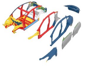
Figure 4: Press Hardened Hot Stamped Steel in the Model Y Body Side Outers and Inners. Dark blue = mild steel; yellow = high strength steel; red = ultra high strength steelT-48
Li Auto L8
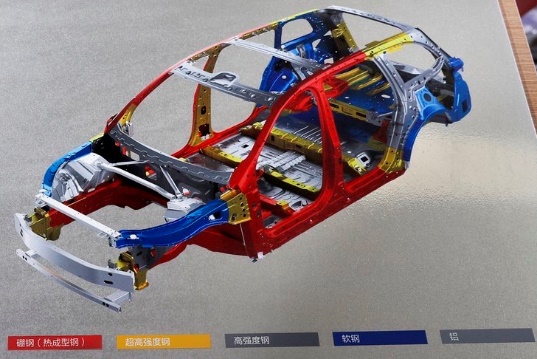
The Li L8 is a luxury range-extended battery electric SUV equipped with an autonomous driving system produced by Chinese manufacturer Li Auto. Hot-formed steel is used in safety-critical areas such as the A-pillar, B-pillar, C-pillar, door sills, and door intrusion beams, accounting for 28.9% of the entire body-in-white, with high strength steels accounting for over 75% of the body structure. Hot-formed steel parts are shown in red in Figure 5, with ultra high strength steel shown in yellow, high strength steel shown in dark gray, and mild steel parts colored in blue.X-2
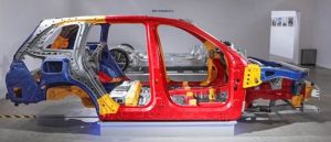
Figure 5: Nearly 30% of the Li Auto L8 body-in-white is made from Hot Stamped Press Hardened Steels.X-2

Honda Civic
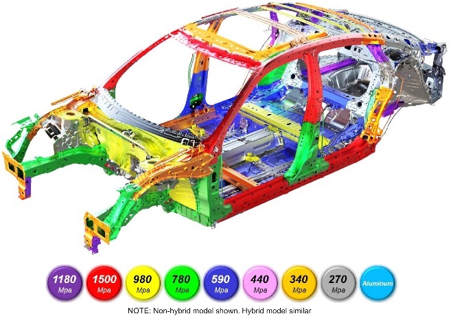
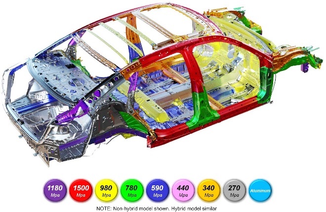
The 2025 Honda Civic Hybrid, based on the 11th Generation Honda Civic platform launched for the 2022 model year, uses high strength and advanced high strength steel throughout their Next-Generation Advanced Compatibility Engineering™ (ACE™) body structure. Honda defines high-strength steel (HSS) as any steel with a tensile strength of 340 MPa or higher. Ultra-high-strength steels (UHSS) are those with a tensile strength of 980 MPa or higher.H-68
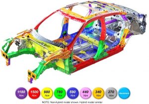
Figure 6: The body construction of the 2025 Honda Civic uses high-strength steel and advanced high-strength steel for enhanced passenger protection.H-67

Nissan Rogue
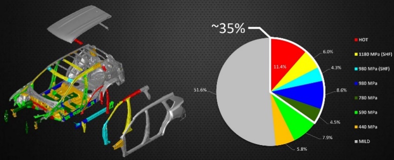
The 3rd Generation Nissan Rogue, launched for the 2021 Model Year, makes extensive use of advanced high strength steels, including 3rd Gen AHSS.
Nissan deploys AHSS grades for 35% of the body structure, an increase of more than 10% compared to the prior version.L-67 Hot stamped press hardened steels, not used in the prior model, helps this Nissan Rogue achieve improved safety, fuel efficiency, and customer satisfaction. Figure 7 shows how various steel grades are deployed in the body structure.

Figure 7: Nissan Rogue Body-in-White Uses Press Hardened Steels and 3rd Generation Advanced High Strength Steel Grades.L-67
The Rogue’s B-pillar is cold stamped from a tailor welded blank of super high formable 980 (SHF 980) and super high formable 1180 (SHF 1180) steel, allowing Nissan to realize the same benefits of hot stamping at a much higher productivity, as highlighted in Figure 8 L-67. Both of these super high formable grades can be considered 3rd Generation Advanced High Strength Steels. (See the information on the 2018 Infinity QX50 SUV here) .
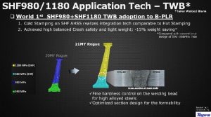
Figure 8: The Nissan Rogue uses a laser welded blank formed from two 3rd Generation Advanced High Strength Steels. L-67
A critical enabling technology in the use of SHF 980 and SHF 1180 is the development of design guidelines for welding stacks that include those materials. These guidelines use weld gun control and panel positioning to prevent unneeded additional tensile stress in the weld stack.L-66 Minimizing the tensile stress in the weld stack helps address the risk of liquid metal embrittlement as does extending the hold time portion of the spot weld cycle in order to lower the temperature prior to releasing the electrodes.L-67
Chevrolet Blazer EV
The Chevrolet Blazer EV is built on the same architecture as the Chevrolet Equinox EV, Cadillac Lyriq, Honda Prologue, Acura ZDX EV, among others.E-14
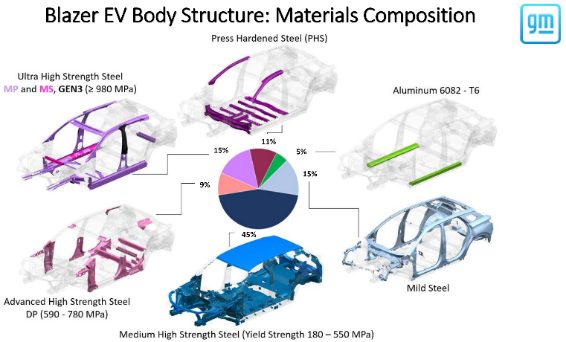
Fifteen percent of the body structure are ultra high strength steels, including multiphase, martensitic, and 3rd Generation Steels having a tensile strength of at least 980 MPa. An additional 11% are stamped from press hardened steels. The breakdown of the Blazer EV body structure is shown in Figure 9.
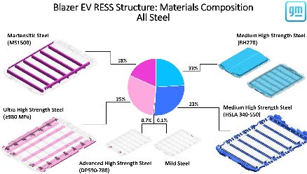
Regarding the battery pack, part of the General Motors battery management system known as the Rechargeable Energy Storage System (RESS), 43% of the all-steel construction is made from grades with tensile strength of at least 980 MPa. (Figure 10).
Instead of using press hardening steels for the B-pillar, General Motors stated that there was a cost savings in addition to a mass savings by using 3rd Generation AHSS in this application. This required development of a material grade specification capable of use globally, along with forming and welding practices for robust production. (Figure 11).

Figure 9: 35% of the Chevrolet Blazer EV body structure is made from Advanced High Strength Steels with a tensile strength of at least 590 MPa. E-14
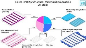
Figure 10: 43% of the Chevrolet Blazer EV Rechargeable Energy Storage System structure is made from Advanced High Strength Steels with a tensile strength of at least 980 MPa. E-14
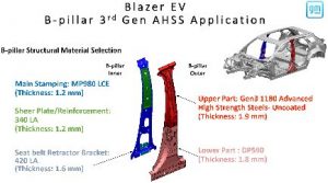
Figure 11: Use of 3rd Generation Advanced High Strength Steels in the B-Pillar of the Chevrolet Blazer EV led to cost savings and mass savings while maintaining crash and safety performance. E-14
Blog, homepage-featured-top, main-blog, News
The transportation industry’s contribution to greenhouse gas (GHG) emissions and global warming is well documented and understood. Vehicle OEMs, fleet operators, and transport users all have responsibilities to reduce environmental impacts on the planet and contribute to meeting global emissions regulations.
Mobility as a Service (MaaS) solutions like WorldAutoSteel’s flaghip Steel E-Motive (SEM) program have the potential to contribute to a reduction in GHG emissions, helping to achieve these global targets and specific policy objectives. The Steel E-Motive engineering report, released in 2023, addresses the impact of emissions reduction using Life Cycle Assessment, with key results summarized in this article.
Introduction to Life Cycle Assessment
Life Cycle Assessment (LCA) is a methodology that evaluates the environmental impact of a product across its entire lifecycle. By understanding the impact across the entire vehicle life cycle, vehicle manufacturers evaluate trade-offs and assess the net impact of the product they’re using.
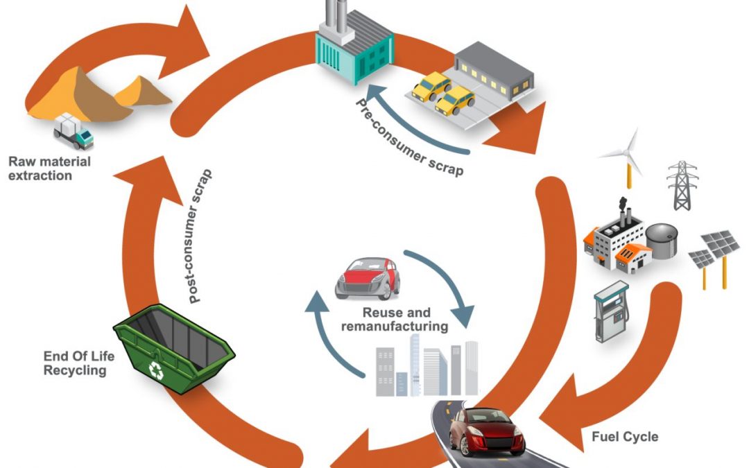
Cradle-to-grave assessments utilize a boundary that includes impacts from the production phase (including raw material extraction and vehicle production), the use phase (including fuel or electricity as well as consumables like tires and fluids) and the end-of-life phase, which could include disposal and/or recyling of the product, as shown in Figure 1. We applied LCA throughout the development of the SEM concept.
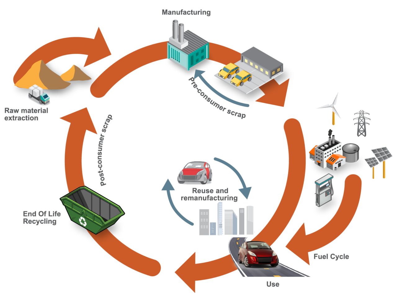
Figure 1. SEQ Figure \* ARABIC 1 Life Cycle Assessment, considering the entire life of the vehicle, from raw material extraction to end of life
LCA can cover a range of environmental impacts; however, for the SEM program, we focused on GHG emissions through the GWP-100 indicator and total energy consumption using Cumulative/Primary Energy Demand and Fossil Energy Consumption indicators.
Reference Taxi (Baseline) Vehicle
A key consideration in LCA calculations is establishing an appropriate reference vehicle. For this program, the following criteria was used:
- Present day (~2020) battery electric vehicle (BEV) operating in taxi mode with a driver and one occupant with vehicle/battery lifetime assumptions of 300,000km, and use of 100 percent conventional steel/aluminum.
- Vehicle end-of-life methodology using the Avoided Burden Approach, where recycled metals are assumed to displace equivalent quantities of their virgin counterparts and assigned corresponding emission and energy demand credits.
- Assumption of 50 percent pyrometallurgical recycling for the battery packs.
- Estimated reference taxi vehicle curb weight using the statistical reference data study (Figure 2), resulting in an estimated curb weight of 1,949kg.
- Material utilization based on data from a similar vehicle specification, as shown in Figure 3.
- Vehicle occupancy rate assumptions of 1.4, based on a combination of both “empty” and passenger-carrying journeys.
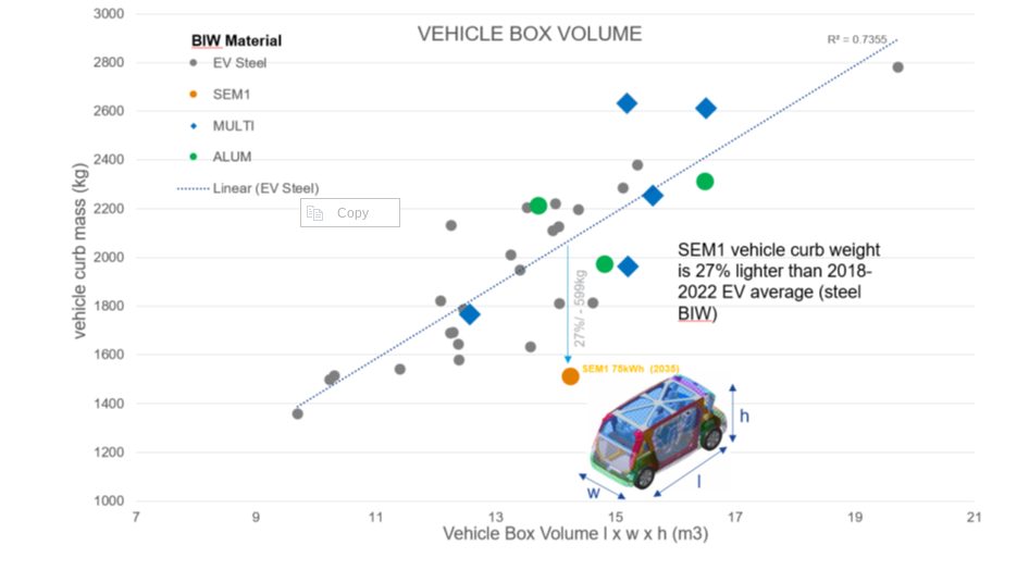
Figure 2. Vehicle curb weight versus box volume comparison. Reference vehicle data; source www.a2mac1.com
Steel E-Motive “Default” Vehicle
SEM vehicle life cycle calculations assume a hypothetical 2030 manufacture and start-of-operation date of 2030 to 2035. We updated the electricity grid supply mix to include the average of the International Energy Agency (IEA) scenario estimates for 2030 and 2040.
- We applied the nominal SEM1 vehicle curb weight of 1,512kg in the LCA model, and updated the vehicle Bill of Materials.
- As with the reference vehicle, we adopted the Avoided Burden Approach as the default for end-of-life calculation.
Life Cycle Assessment Results
Figure 3 below highlights absolute calculated life cycle GHG emissions, in units of kgCO2e/ passengerꞏkilometer studied, with the individual contributions of vehicle manufacturing, vehicle use, and end-of-life phase presented.
The analysis evaluated two reference/baseline conditions and nine SEM sensitivity studies, see Figure 4. These included alternative assumptions on LCA end-of-life modeling methodology, lifetime vehicle activity (and battery lifetime), alternative operational energy consumption sensitivities, sensitivities on the use of ‘green’ steel, and vehicle occupancy rates.
The accompanying pie chart shows the breakdown and contributions to the vehicle manufacture GHG for the baseline SEM scenario (2).
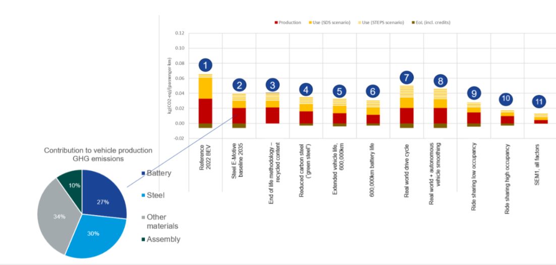
Figure 3. SEQ Figure \* ARABIC 2 life cycle assessment GHG results
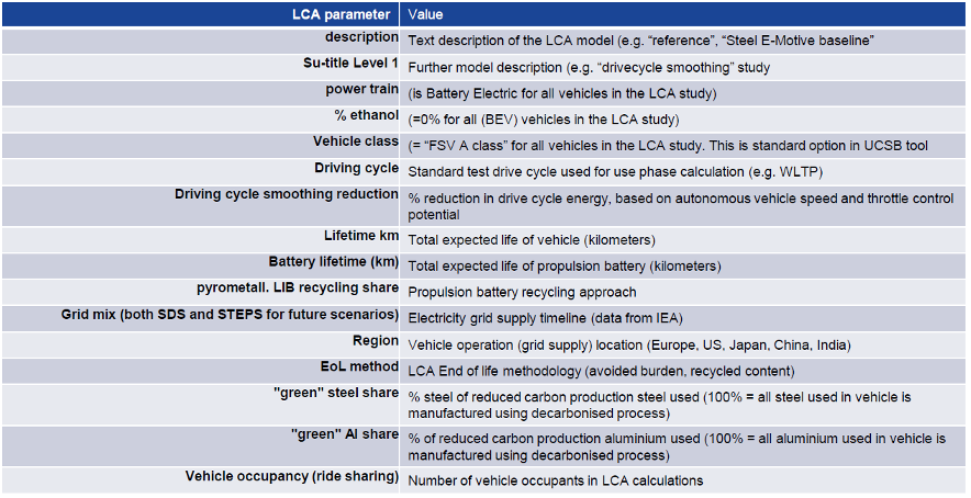
Figure 4. Reference/baseline conditions and SEM sensitivity studies
Life Cycle Assessment Conclusions
Based on the parameters outlined, applying LCA to SEM concept demonstrated the designs’ potential to reduce lifecycle greenhouse gas emissions by up to 86 percent compared to a present-day battery electric vehicle operating as a taxi.
This potential can be realized by adopting the following measures:
- Reducing vehicle production and manufacturing embedded emissions by utilizing 100 percent reduced carbon (“green”) steel
- Improving battery technology and increasing the use of renewable electricity in battery manufacturing; as well as increasing/improving battery recycling
- Ensuring the vehicle weight of autonomous vehicles is managed, and the potential weight reduction benefits realized and implemented. The SEM body structure and battery housing demonstrate good weight efficiency.
- Increasing the overall lifespan of the vehicle and battery. The fatigue and durability properties of AHSS can enable enhanced vehicle lifetime. The SEM battery design allows easy replacement of specific modules, enabling an overall extended battery life.
- Autonomous vehicle control smooths the driving cycle. The vehicle acceleration and deceleration rates can be optimized to match the driving conditions and road topography, reducing energy consumption and subsequent GHG emissions.
- Increasing passenger occupancy rates to at least three per vehicle via MaaS.
The projected net GHG emissions for the SEM vehicle operating with the flexibilities described above already represent a significant reduction when compared to the current baseline.
Achieving net zero emissions would require additional measures like offsetting manufacturing impacts (e.g., through compensatory credits from atmospheric carbon capture and storage) and transitioning to a 100 percent renewable electricity grid.
Moving Toward Net Zero
Taking a Life Cycle Assessment approach to the SEM concept demonstrates the possibilities for engineering future mobility vehicles that continue to move us closer to a net zero future. For more information about the Steel E-Motive program, download the engineering report here: https://bit.ly/SEM_Eng_Report

Thanks go to Russ Balzer for his contribution of this article to the AHSS Insights blog. As.technical director at WorldAutoSteel, he leads technical programs and oversees the organization’s work in research, modeling, and advocacy for Life Cycle Assessment in the automotive sector. An LCA Certified Professional through the American Center for Life Cycle Assessment (ACLCA), he also acts as the WorldAutoSteel liaison to the worldsteel LCA Expert Group.
Blog, homepage-featured-top, main-blog, News
The Steel E-Motive concept features an innovative battery housing design and laser welded blank door ring created using part integration to reduce mass and cost.
Battery Carrier Frame System
The Steel E-Motive battery modules, cooling plates & hoses, electrical connectors, and battery management system are mounted to an AHSS carrier frame. This assembly is then bolted to the body structure. The body in white floor assumes the role of the battery top cover, providing both cost and weight savings; an AHSS bottom cover seals and provides underbody protection.
You can view the details about the SEM1 final battery concept in section 7.3 in the SEM Engineering Report: https://bit.ly/SEM_Eng_Report
The Steel E-Motive Battery Carrier Frame
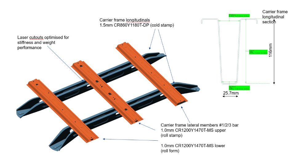
The battery carrier frame forms an integral part of the body structure load path. It connects to the front and rear longitudinals and the floor cross members. Two different manufacturing approaches and designs were considered for the longitudinals.
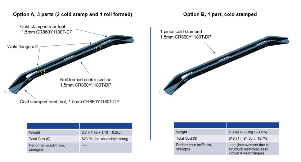
Option A considered a 3-part longitudinal design, with unique cold stampings for the front and rear “feet” and a roll-formed center section. The part integration is accomplished via an overlap weld flange and spot welding. Dual Phase 1180MPa UTS grade AHSS was selected based on the strength required for crash load reaction and enabling a lower 1.5mm gauge thickness. Initially, it was perceived that the roll-formed center section design would enable an overall lower-cost solution.
Option B replaces the 3-piece design with a single, cold-stamped part, again using 1.5mm DP1180 AHSS. The deep draw profile and material’s low ductility presented formability challenges for the cold stamping of the longitudinal. These were overcome by adjustments to the deep draw profile and optimization of the die and stamping parameters.
A comparison of the two designs shows that a small weight saving and a significant cost reduction of $4.30 (18.7%) per longitudinal is achieved with the single cold-stamped design. The vehicle NVH, static stiffness, and crash performance were also calculated to be superior for the integrated design Option B.
Therefore, Option B, provides cost, weight, and performance benefits compared to the multiple part design Option A.
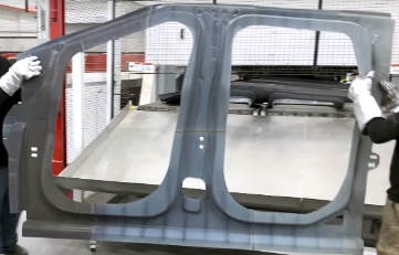
Laser Welded Blank Door Ring Created Using Part Integration
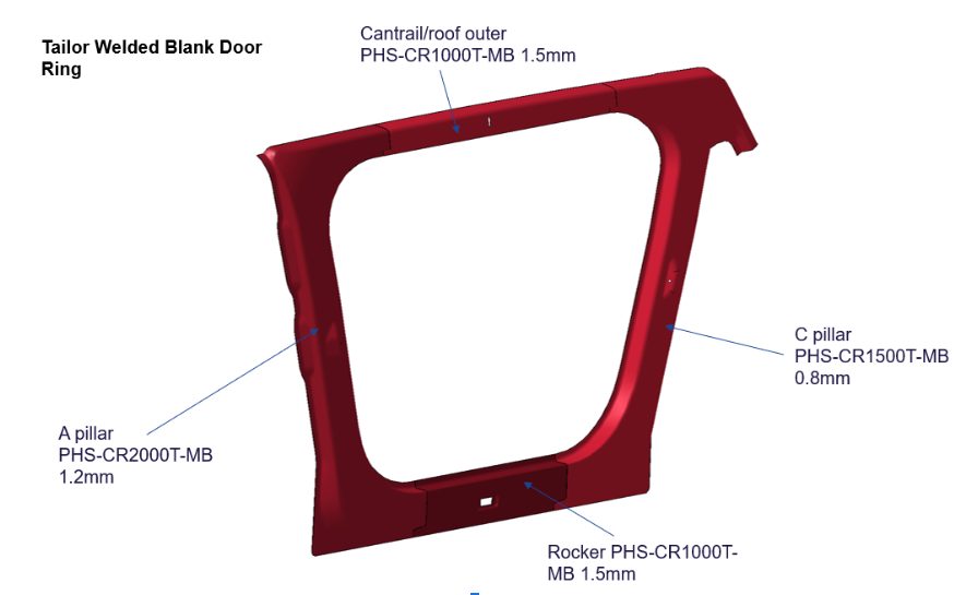
Part integration via laser-welded blanks allows different steel grades, thicknesses, and coating types to be combined into a single blank before the fabrication process. The Steel E-Motive door ring is a hot-formed part consisting of four different blanks with different AHSS grades and thicknesses.
The performance requirements for the specific region determine the grades and thicknesses for each blank. The A-pillar requires very high strength to protect the front occupants in the event of a high-speed frontal or side collision. Lower strengths and grades are required for the rocker, cantrail, and C-pillar parts. The four blanks are cut from the native material grade coil and joined using laser welding to form the single-door ring blank. This then undergoes a hot-forming process to achieve the design door ring shape and the Ultra High-Strength properties of press-hardened steel.
Consolidating four blanks into a single part significantly reduces scrap compared to a single blank part, and simplifies part manufacturing by eliminating other stamping and assembly processes with related cost savings. Higher material utilization means less steel is produced, resulting in lower costs and lower GHG emissions. The laser weld between the blanks helps achieve greater strength and stiffness to spot-welding four individual blanks.
Outlook
The latest AHSS grades and fabrication processes allow engineers to reduce the number of parts or blanks used in automotive body structures. Several part integration and consolidation processes have been applied and demonstrated in the Steel E-Motive concept. Part consolidation results in lower scrap rates, improved material utilization, reduced part cost, and GHG emissions. The integrated structures also improve overall stiffness and strength performance.

Thanks go to Neil McGregor for his contribution of this article to the AHSS Insights blog. As Chief Engineer, Systems Integration at Ricardo, Neil has extensive knowledge of lightweight, advanced materials across all major vehicle sub-systems and leads the Steel E-Motive vehicle engineering program at Ricardo.
Blog, homepage-featured-top, main-blog, News
Tailor-welded blanks (TWBs) allow the combination of different steel grades, thicknesses, and even coating types into a single blank. This results in stamping a single component with the right material in the right place for on-vehicle requirements. This technology allows the consolidation of multiple stampings into a single component.
One example is the front door inner. A two-piece design will have an inner panel and a reinforcement in the hinge area. As shown in Figure 1, a TWB front door inner incorporates a thicker front section in the hinge area and a thinner rear section for the inner panel, providing on-vehicle mass savings. This eliminates the need for additional components, reducing the tooling investment in the program. This also simplifies the assembly process, eliminating the need to spot weld a reinforcement onto the panel.
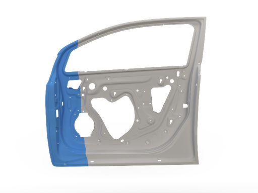
Figure 1 – Front Door Inner
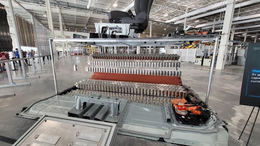
Today, large opportunities exist to consolidate components in a BEV in the battery structure. Design strategies vary from different automakers, including how the enclosure is constructed or how the battery mounts into the vehicle. The battery tray can have over 100 stamped components, including sealing surfaces, structural members, and reinforcements (Munro Live – Munro and Associates, 2023)M-68. As an idea, a battery tray perimeter could be eight pieces, four lateral and longitudinal members, and four corners. The upper and lower covers are two additional stamped components, for a total of ten stampings that make up the sealing structure of the battery tray. On a large BEV truck, that results in over 17m of external sealing surfaces.
Part consolidation in the battery structure provides cost savings in material requirements and reduced investment in required tooling. Another benefit of assembly simplification is improved quality. Fewer components mean fewer sealing surfaces, resulting in less rework in the assembly process, where every battery tray is leak-tested.
The deep-drawn battery tub is a consolidated lower battery enclosure and perimeter. This can be seen in Figure 2; a three-piece welded blank incorporates a thicker and highly formable material at the ends and in the center section, either a martensitic steel for intrusion protection or a low-cost mild steel. This one-piece deep-drawn tub reduces the number of stampings and sealing surfaces, resulting in a more optimized and efficient design when considered against a multi-piece assembly. In the previous example of a BEV truck, the deep-drawn battery tub would reduce the external sealing surface distance by 40%. To validate this concept, component level simulations of crash, intrusion, and formability were conducted. As well as a physical prototype built that was used for leak and thermal testing (Yu, 2024)Y-14 with the outcomes proving the validity of this concept, as well as developing preliminary design guidelines. Additional work is underway to increase the depth of the draw while minimizing the draft angle on the tub stamping.
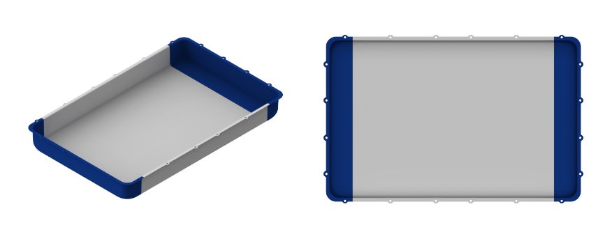
Figure 2 – Deep Battery Tub
In most BEVs today, the passenger compartment has a floor structure common in an ICE vehicle. However, the BEV also has a top cover on the battery assembly that, in most cases, is the same size as the passenger compartment floor. In execution of part consolidation, the body floor and battery top cover effectively seal the same opening and can be consolidated into one component. An example is shown below, where seat reinforcements found on the vehicle floor are integrated into the battery top cover, and the traditional floor of the vehicle is removed. Advanced high-strength steels are used in different grades and thicknesses. Figure 3 and Figure 4 show what the TWB battery top cover looks like on the assembly.
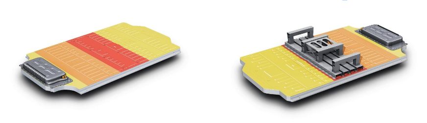
Figure 3 + Figure 4 – TWB Battery Top Cover
Vehicle assembly can also be radically simplified as front seats are mounted on the battery before being installed in the vehicle as shown in Figure 5, the ergonomics of the assembly operation are improved by increased access inside the passenger compartment through the open floor.
Figure 5 – Ergonomics of the Assembly Operation
Cost mitigation is more important than ever before, with reductions in piece cost and investment and assembly costs being important. At the foundation BEVs currently have cost challenges in comparison to their ICE counterparts, however the optimization potential for the architecture remains high, specifically in part consolidation. Unique concepts such as the TWB deep-drawn battery tub and integrated floor/battery top cover are novel approaches to improve challenges faced with existing BEV designs. TWB applications throughout the body in white and closures remain relevant in BEVs, providing further part consolidation opportunities.

Thanks go to Isaac Luther for his contribution of this article to the AHSS Insights blog. Luther is a senior product engineer on the new product development team at TWB Company. TWB Company is the premier supplier of tailor-welded solutions in North America. In this role, Isaac is responsible for application development in vehicle body and frame applications and battery systems. Isaac has a Bachelor of Science in welding engineering from The Ohio State University.
Blog, homepage-featured-top, Joining, Joining Dissimilar Materials, main-blog, News, Resistance Spot Welding, Resistance Welding Processes, RSW Modelling and Performance, RSW of Dissimilar Steel
This blog is a short summary of a published comprehensive research work titled: “Peculiar Roles of Nickel Diffusion in Intermetallic Compound Formation at the Dissimilar Metal Interface of Magnesium to Steel Spot Welds” Authored by Luke Walker, Carolin Fink, Colleen Hilla, Ying Lu, and Wei Zhang; Department of Materials Science and Engineering, The Ohio State University
*****
There is an increased need to join magnesium alloys to high-strength steels to create multi-material lightweight body structures for fuel-efficient vehicles. Lightweight vehicle structures are essential for not only improving the fuel economy of internal combustion engine automobiles but also increasing the driving range of electric vehicles by offsetting the weight of power systems like batteries.
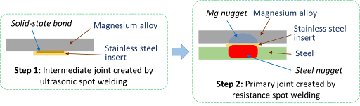
To create these structures, lightweight metals, such as magnesium (Mg) alloys, have been incorporated into vehicle designs where they are joined to high strength steels. It is desirable to produce a metallurgical bond between Mg alloys and steels using welding. However, many dissimilar metal joints form intermetallic compounds (IMCs) that are detrimental to joint ductility and strength. Ultrasonic interlayered resistance spot welding (Ulti-RSW) is a newly developed process that has been used to create strong dissimilar joints between aluminum alloys and high-strength steels. It is a two-step process where the light metal (e.g., Al or Mg alloy) is first welded to an interlayer (or insert) material by ultrasonic spot welding (USW). Ultrasonic vibration removes surface oxides and other contaminates, producing metal-to-metal contact and, consequently, a metallurgical bond between the dissimilar metals. In the second step, the insert side of the light metal is welded to steel by the standard resistance spot welding (RSW) process.
Cross-section View Schematics of Ulti-RSW Process Development
For resistance spot welding of interlayered Mg to steel, the initial schedule attempted was a simple single pulse weld schedule that was based on what was used in our previous study for Ulti-RSW of aluminum alloy to steel . However, this single pulse weld schedule was unable to create a weld between the steel sheet and the insert when joining to Mg. Two alternative schedules were then attempted; both were aimed at increasing the heat generation at the steel-insert interface. The first alternative schedule utilized two current pulses with Pulse 1, high current displacing surface coating and oxides and Pulse 2 growing the nugget. The other pulsation schedule had two equal current pulses in terms of current and welding time.
Lap shear tensile testing was used to evaluate the joint strength using the stack-up schematically, shown below. Note the images of Mg and steel sides of a weld produced by Ulti-RSW.
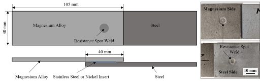 Lap Shear Tensile Test Geometry and the Resultant Weld Nuggets
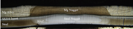
An example of a welded sample showed a distinct feature of the weld that is comprised of two nuggets separated by the insert: the steel nugget formed from the melting of steel and insert and the Mg nugget brazed onto the unmelted insert. This feature is the same as that of the Al-steel weld produced by Ulti-RSW in our previous work. Although the steel nugget has a smaller diameter than the Mg nugget, it is stronger than the latter, so the failure occurred on the Mg sheet side.
Joint strength depends on several factors, including base metal strength, sheet thickness, and nugget size, making it difficult to compare how strong a weld truly is from one process to another. To better compare the dissimilar joints created by different processes, joint efficiency, a “normalized” quantity was calculated for various processes used for dissimilar joining of Mg alloys to steels in the literature, and those results, along with the efficiencies of Ulti-RSW with inserts, are shown together below. Most of the literature studies also used AZ31 as the magnesium base metal. The ones with high joint efficiency (about 53%) in the literature are resistance element welding (REW) and friction stir spot welding (FSSW). In our study, Ulti-RSW with SS316 insert was able to reach an excellent joint efficiency of 71.3%, almost 20% higher than other processes.
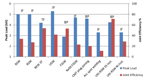 Process Evaluation and Comparison

Thanks are given to Menachem Kimchi, Associate Professor-Practice, Dept of Materials Science, Ohio State University, and Technical Editor – Joining, AHSS Application Guidelines, for this article.