Blog, main-blog, News
As robotaxi companies in the USA prepare to launch their autonomous vehicles in more cities, safety is in the spotlight again. And rightly so. Autonomous vehicle safety challenges must be addressed and with the Steel E-Motive Level 5 autonomous concept, we did that.
Many autonomous mobility service companies have relied on two factors when developing their vehicles: active safety systems which help the vehicle avoid or mitigate the extent of a crash, and a maximum vehicle speed limit, which will reduce the extent of injuries to the occupants.
But the fact is that these vehicles are going to be out in mixed-mode traffic situations. There will be accidents – however much we all attempt to do everything possible to avoid them. When we developed the Steel E-Motive (SEM) body structure concepts for fully autonomous ride-sharing electric vehicles, we agreed on two basic principles – that these vehicles would operate at high speeds (top speed of 130 kph) in mixed mode traffic conditions, and that we, therefore, needed to engineer passive safety structures that met global high-speed crash requirements to protect occupants and the battery system in these use-case conditions. In this process, we discovered that no other provider of autonomous ride-sharing electric vehicles had fully shared details of passive safety structures engineered to those same high-speed crash standards. Autonomous vehicle safety had been addressed only on a limited basis.
Fortunately, our vehicle design process benefitted from a massive portfolio of modern advanced high-strength steels (AHSS) available through member companies of WorldAutoSteel. Steel E-Motive (SEM) was developed to show how AHSS can enable sustainable, comfortable, economical, and safe ride-sharing vehicles by 2030.
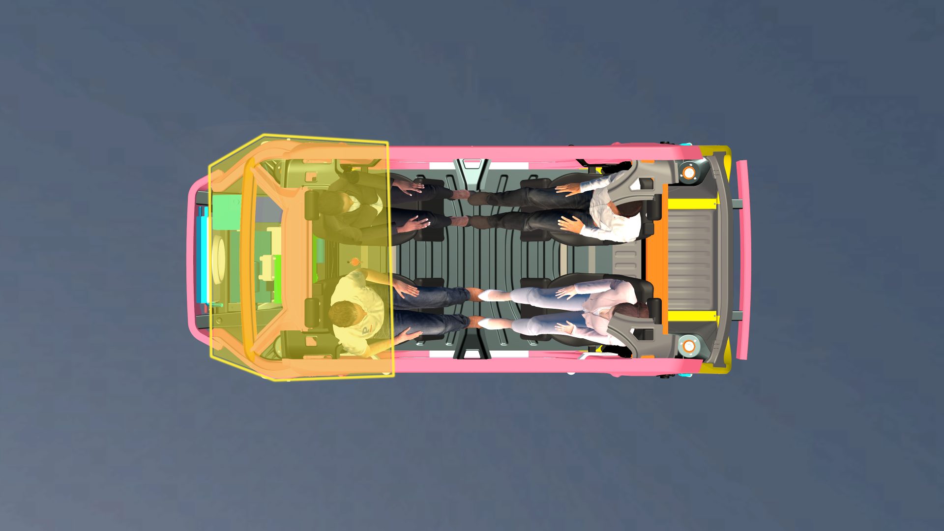
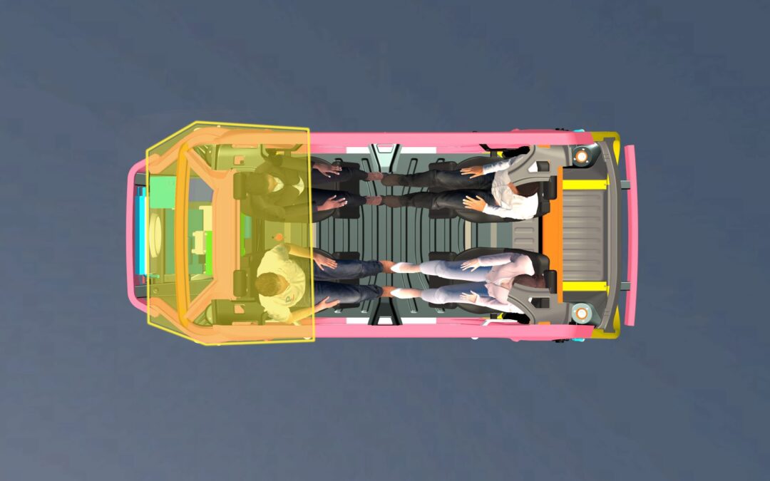
The AHSS Extended Passenger Protection Zone provides excellent cabin intrusion protection and ultimately lower risk of injury. PHS provides formability for challenging geometries, and Martensitic steel (MS) provides the strength to limit intrusion.
Visit this link to download the full engineering report: Steel E-Motive
The result is one of the first robotaxis to fully detail and report compliance to global high-speed safety standards. In developing Steel E-Motive, we targeted conformity with seven US crash standards, including US NCAP (New Car Assessment Program) IIHS and FMVSS (Federal Motor Vehicle Safety Standards) front, side, and rear impact tests while also assessing performance against worldwide protocols, including NHTSA (US) Euro NCAP (European) and China’s GB 38031 standard for battery protection.
As an example, Steel E-Motive achieves the highest IIHS rating of “good.” This is particularly important as IIHS (the US-based Insurance Institute for Highway Safety) is highly regarded for its dedication to reducing deaths, injuries, and property damage from motor vehicle crashes.
Most production vehicles use new generation, advanced high-strength steels, and technologies. We had no fewer than 64 AHSS materials to select from, enabling us to choose exactly the right steel for every need and purpose in the vehicle, including safety protection. These make a car stronger, more fuel efficient, and safer.
Nearly all vehicles on the road today are made of steel because it has the broadest range of properties while being the most affordable structural material for designing safe vehicles. Steel has a unique capacity to absorb an impact, and, therefore, to diffuse crash energy. It also becomes harder when it’s crushed, which means it will become stronger on impact, retarding further penetration into the vehicle’s passenger zone.
Taking on Autonomous Vehicle Safety Challenges
Here is an outline of how we designed steel’s benefits into the Steel E-Motive (SEM) concept when considering front and side crashes.
SEM features a high-strength front protection zone, which reacts to the crush loads and minimizes intrusion for the occupants in front crashes. The crush zones have been engineered to decelerate the vehicle progressively. The longitudinal mid rails, featuring tailor-welded blanks fabricated with Dual Phase steels, are tuned to give a lower deceleration pulse into the passenger cabin to minimize injury threat. The side crush rails are designed to minimize intrusion into the cabin for occupant protection. Finally, a novel design geometry and Press Hardened Steels enable the new glance beam architecture to force the vehicle off of the Small Offset barrier; the resulting “glance-off” achieves significantly reduced crash energy and pulse into the passenger cabin.
When considering side crashes, we engineered the body structure for the IIHS 60kph deformable barrier test and 30kph side pole test, assessing both occupant and battery protection and achieving the IIHS “good” performance rating. Our side structures are comprised of a large one-piece tailor-welded door ring fabricated with press hardened steels, the TRIP steel B pillar housed in the side scissor doors, and a roll-formed hexagon rocker beam fabricated with Dual Phase steel.
These attain a very safe design, giving good levels of protection for both the occupants and battery modules, exceeding 30mm intrusion clearance at critical measurement points.
SEM was also engineered for rear crash and roof crush, and once again, the robust steel-intensive architecture exceeds crash standard requirements.
Electric-powered vehicle sales are accelerating, reflecting industry investment, and will soon achieve market domination from the combustion engine. In megacities, where congestion, pollution, and exorbitant vehicle ownership costs reign, Autonomous cars will replace drivers, and ride-sharing will become the norm. As we look into the future and recognize the need for these vehicles to offer comfortable, safe, affordable, and sustainable transportation, we will still be designing them by harnessing the unique properties of steel.
Visit this link to download the full engineering report: Steel E-Motive
Blog, homepage-featured-top, main-blog, News, Resistance Spot Welding, RSW of Dissimilar Steel, Tool & Die Professionals
Urbanization and waning interest in vehicle ownership point to new transport opportunities in megacities around the world. Mobility as a Service (MaaS) – characterized by autonomous, ride-sharing-friendly EVs – can be the comfortable, economical, sustainable transport solution of choice thanks to the benefits that today’s steel offers.
The WorldAutoSteel organization is working on the Steel E-Motive program, which delivers autonomous ride-sharing vehicle concepts enabled by Advanced High-Strength Steel (AHSS) products and technologies.
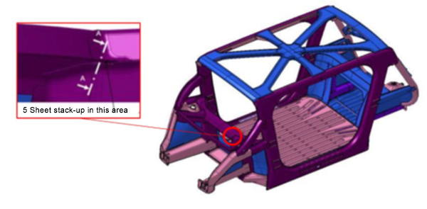
The Body structure design for this vehicle is shown in Figure 1. It also indicates the specific joint configuration of 5 layers AHSS sheet stack-up as shown in Table 1. Resistance spot welding parameters were developed to allow this joint to be made by a single weld. (The previous solution for this welded joint is to create one spot weld with the bottom 3 sheets indicated in the table and a second weld to join the top 2 sheets, combining the two-layer groups to 5T stack-up.)
NOTE: Click this link to read a previous AHSS Insights blog that summarizes development work and recommendations for resistance spot welding 3T and 4T AHSS stack-ups: https://bit.ly/42Alib8
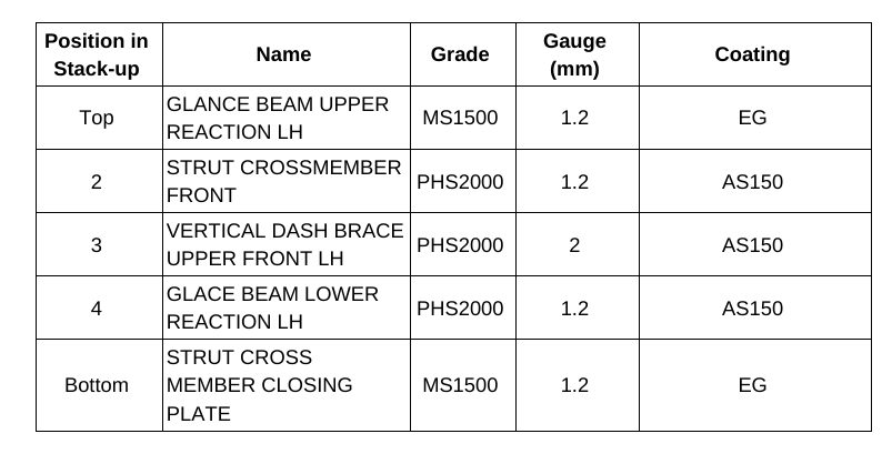
Table 1. Provided materials organized in stack-up formation showing part number, name, grade, gauge in mm, and coating type. Total thickness = 6.8 mm
The same approach of utilizing multiple current pulses with short cool time in between the pulses was shown to be most effective in this case of 5T stack-up. It is important to note that in some cases, the application of a secondary force was shown to be beneficial, however, it was not used in this example.
To establish initial welding parameters simulations were conducted using the Simufact software by Hexagon. As shown in Figure 2, the final setup included a set of welding electrodes that clamped the 5-layer AHSS stack-up. Several simulations were created with a designated set of welding parameters of current, time, number of pulses, and electrode force.
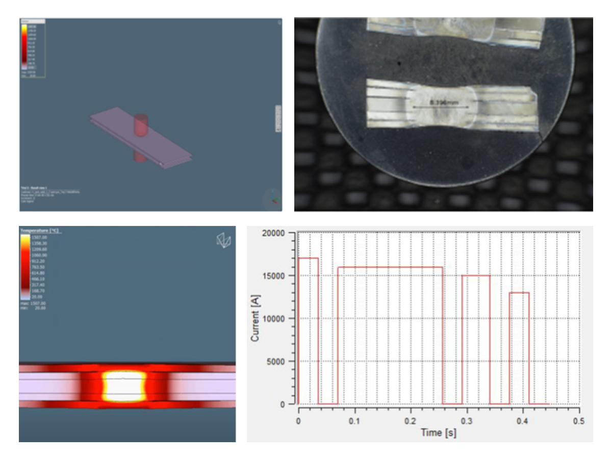
Figure 2. Example of simulation and experimental results showing acceptable 5T resistance spot weld (Meets AWS Automotive specifications)

Thanks is given to Menachem Kimchi, Associate Professor-Practice, Dept of Materials Science, Ohio State University and Technical Editor – Joining, AHSS Application Guidelines, for this article.
Blog, homepage-featured-top, main-blog, News
This month’s blog was contributed by Peter Ulintz, Precision Metalforming Association. This content originally appeared in the September 2023 issue of MetalForming Magazine under the title “Stronger AHSS Knowledge Required for Metal Stampers” and has been reproduced with the permission of MetalForming Magazine.
Metal stampers and die shops experienced with mild and HSLA steels often have problems making parts from AHSS grades. The higher initial yield strengths and increased work hardening of these steels can require as much as four times the working loads of mild steel. Some AHSS grades also have hardness levels approaching the dies used to form them.
Dies Get Tougher
Metal stampers and die shops experienced with mild and HSLA steels often have problems making parts from AHSS grades. The higher initial yield strengths and increased work hardening of these steels can require as much as four times the working loads of mild steel. Some AHSS grades also have hardness levels approaching the dies used to form them.
The higher stresses required to penetrate higher-strength materials require increased punch-to-die clearances compared to mild steels and HSLA grades. Why? This clearance acts as leverage to bend and break the slug out of the sheet metal. Stronger materials need longer levers to bend the slug. The required clearance is a function of the steel grade and tensile strength, and sheet thickness.
Increasing cutting clearance can result in punch cracking and head breakage due to higher snapthrough loads and reverse-unloading forces within the die. Adding shear angles to the punch face helps reduce punch forces and reverse unloading.
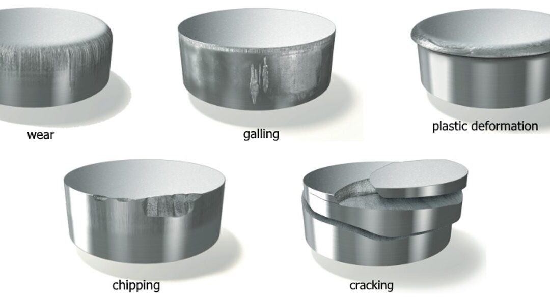
Tight-cutting clearances increase the tendency for die galling and chipping. The severity of galling depends on the surface finish and microstructure of both the tool steel and work material. Chipping can occur when process stresses are high enough to cause low-cycle fatigue of the tooling material, indicating that the material lacks toughness.
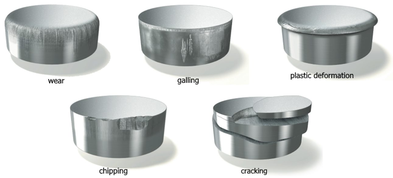
Stamping Tool Failure Modes (Citations T-20 and U-7)
Tempering of tools and dies represents a critical heat-treatment step and serves more than one purpose, but of primary concern is the need to relieve residual stresses and impart toughness. Dies placed in service without proper tempering likely will experience early failure.
Dies made from the higher-alloy tool-steel grades (D, M or T grades) require more than one tempering step. These grades contain large amounts of retained austenite and untempered martensite after the first tempering step and require at least one more temper to relieve internal stresses, and sometimes a third temper for even greater toughness.
Unfortunately, heat treatment remains a “black-box” process for most die shops and manufacturing companies, which send soft die details to the local heat treat facility, with hardened details returned. A cursory Rockwell hardness test may be conducted at the die shop when the parts return. If they meet hardness requirements, the parts usually are accepted, regardless of how they may have been processed—a problem, as hardness alone does not adequately measure impact toughness.
Machines Get Stronger
The increased forces needed to form, cut and trim higher-strength steels create significant challenges for pressroom equipment and tooling. These include excessive tooling deflections, damaging tipping-moments, and amplified vibrations and snapthrough forces that can shock and break dies—and sometimes presses. Stamping AHSS materials can affect the size, strength, power and overall configuration of every major piece of the press line, including material-handling equipment, coil straighteners, feed systems and presses.
Here is what every stamper should know about higher-strength materials:
- Because higher-strength steels require more stress to deform, additional servo motor power and torque capability may be needed to pull the coil material through the straightener. Additional back tension between the coil feed and straightening equipment also may be required due to the higher yield strength of the material in the loop as the material tries to push back against the straightener and feed system.
- Higher-strength materials, due to their greater yield strengths, have a greater tendency to retain coil set. This requires greater horsepower to straighten the material to an acceptable level of flatness. Straightening higher-strength coils requires larger-diameter rolls and wider roll spacing in order to work the stronger material more effectively. But increasing roll diameter and center distances on straighteners to accommodate higher-strength steels limits the range of materials that can effectively be straightened. A straightener capable of processing 600-mm-wide coils to 10 mm thick in mild steel may still straighten 1.5-mm-thick material successfully. But a straightener sized to run the same width and thickness of DP steel might only be capable of straightening 2.5 mm or 3.0-mm thick mild steel. This limitation is primarily due to the larger rolls and broadly spaced centers necessary to run AHSS materials. The larger rolls, journals and broader center distances safeguard the straightener from potential damage caused by the higher stresses.
- Because higher-strength materials require greater stress to blank and punch as compared to HSLA or mild steel, they generate proportionally increased snapthrough and reverse-unloading forces. High-tensile snapthrough forces introduce large downward accelerations to the upper die half. These forces work to separate the upper die from the bottom of the ram on every stroke. Insufficient die-clamping force could cause the upper-die half to separate from the bottom of the ram on each stroke, causing fatigue to the upper-die mounting fasteners.
- Because energy is expended with each stroke of the press—and this energy must be replaced—critical attention must focus on the size (horsepower) of the main drive motor and the rotational speed of the flywheel in higher-strength-steel applications. The main motor, with its electrical connection, provides the only source of energy for the press and it must generate sufficient power to meet the demands of the stamping operation. The motor must be properly sized to replace the increased energy expended during each press stroke. For these reasons, some stampers consider the benefits of servo-driven presses for these applications.
As steels becomes stronger, a corresponding increase in process knowledge is required in terms of die design, construction and maintenance, and equipment selection.
You can read more about these topics at these links:
Tooling and Die Wear
Coil Processing Straightening and Leveling
Press Requirements

Thanks go to Peter Ulintz, of the Precision Metalforming Association (PMA) for authoring this article. Ulintz was employed in the metal stamping and tool & die industries for 38 years before joining Precision Metalforming Association (PMA) in 2015. He provides industry-related training and seminars in Stamping Press Operation and Setup; Designing and Building Metal Stamping Dies; Die Maintenance and Troubleshooting; Metal Stamping Design for Manufacturability; Deep Draw Tooling and Process Technology; Stamping Higher Strength Steels; and Problem Solving in the Press Shop. Peter is a contributor to ASM Handbook, Volume 14B, Metalworking: Sheet Forming (2006) and writes the monthly column, Tooling by Design, for PMA’s monthly publication, MetalForming Magazine.

Blog, General, main-blog, News
The Steel E-Motive program–commissioned by WorldAutoSteel in partnership with Ricardo plc–has developed the world’s first fully autonomous electric vehicle body structure concept purpose-fit for ride-sharing. This global steel industry initiative showcases the strength and durability of steel with an eye on playing a pivotal role in reaching net zero emissions targets.
Download the Steel E-Motive Engineering Report
Here, we break down the many benefits of the Steel E-Motive concept that only Advanced High-Strength Steel (AHSS) can enable.
Steel E-Motive Was Conceived as a Level 5 Autonomous Vehicle
The Steel E-Motive concept is designed to be a Level 5 autonomous vehicle, so it does not include any driver interfaces. The design features a spacious, airy cabin with rear-facing front-passenger seat configurations. The B-pillarless structure and unique battery system design offer easy ingress and egress.

The Steel E-Motive concept is designed to be a Level 5 autonomous vehicle.
Designed to Exceed Future Mobility Safety Standards
Modern Advanced High-Strength Steels innovations allow the Steel E-Motive autonomous vehicle to exceed current global high-speed crashworthiness standards. By using AHSS, the Steel E-Motive vehicle is the first to acknowledge compliance with NHTSA and IIHS safety standards publicly.
For example, the 4-passenger B-sized urban concept SEM1 introduced a new front-end passenger protection zone. This design features the small overlap Glance Beam, which forces the car to “glance” off the barrier and reduces passenger cabin intrusion. It also lowers the crash pulse and ultimately minimizes passenger injury. Advanced High-Strength Steels also offer strong battery protection and preserve door ring integrity in this autonomous vehicle.
The Evolution of Advanced High-Strength Steel
Over the past quarter century, vehicle concept projects have showcased the continuous advancement of steel. In 1998, global steelmakers introduced the Ultralight Steel Auto Body, which used one of the earliest forms of AHSS. This project demonstrated steel’s ability to reduce weight without compromising safety.
By 2010, we introduced the Future Steel Vehicle concept. Using 27 AHSS materials, the body structure design reduced mass by over 35%. Steel materials enable these massive reductions while allowing the design to meet global crash and durability requirements.
The Steel E-Motive concepts benefit from no fewer than 64 materials under the AHSS umbrella. The “infinite tunability” of AHSS allows product customization by designers and engineers to select exactly the right steel for every need and purpose in the vehicle.
Key Attributes of the Steel E-Motive Autonomous Vehicle
From lowering the carbon footprint to massively reducing weight, the Steel E-Motive vehicle offers first-of-its-kind benefits for future mobility made possible by AHSS.
Steel allows the vehicle to reduce weight without sacrificing strength. For example, 66% of the Steel E-Motive autonomous vehicle structures’ materials have an Ultimate Tensile Strength of at least 1,000 MPa, and these materials’ weighted average tensile strength is 1259 MPa.
By using 33% Press Hardened Steels and 11% 3rd Generation AHSS, the design includes complex geometries fully formed by hot and cold-stamped gigapascal steels.
In another example, 43% of the Steel E-Motive structure is fabricated from material-efficient processes such as press hardening, hydroforming, roll forming, and roll stamping. With these processes, the steel body design maximizes material utilization and minimizes scrap rate. This means less material is produced, lowering the structure’s carbon footprint. These achievements reduce manufacturing costs to support a profitable margin both for the vehicle manufacturer and the mobility service provider.
Using AHSS, the Steel E-Motive autonomous vehicle’s body structure mass is 25% lower than benchmark vehicles of a similar volumetric footprint. Additionally, Steel E-Motive realizes a 27% lower battery frame cost than a fully enclosed battery design, with 37% mass savings.
In conclusion, the Steel E-Motive program stands as a remarkable testament to the innovative potential of steel in shaping the future of mobility and autonomous vehicles. With its groundbreaking design, the Steel E-Motive concept paves the way for Level 5 autonomous electric vehicles prioritizing safety, sustainability, and efficiency.
Harnessing the unique attributes of AHSS, this global steel industry initiative also showcases the remarkable evolution of steel materials over the years. From Ultralight Steel Auto Body to Future Steel Vehicle, the journey of AHSS has been one of continuous improvement, leading to Steel E-Motive’s exceptional achievements in weight reduction, enhanced safety, and minimized environmental impact.
As we venture into an era of net-zero emissions and advanced mobility solutions, the Steel E-Motive concept proudly positions steel as a driving force in shaping a cleaner, safer, and more connected future.
Download the Steel E-Motive Engineering Report
![Martensite]()
1stGen AHSS, AHSS, Steel Grades
Martensitic steels are characterized by a microstructure that is mostly all martensite, but possibly also containing small amounts of ferrite and/or bainite (Figure 1 and 2). Steels with a fully martensitic microstructure are associated with the highest tensile strength – grades with a minimum specified tensile strength of 1700 MPa are commercially available, and higher strength levels are under development.

Figure 1: Schematic of a martensitic steel microstructure. Ferrite and bainite may also be found in small amounts.

Figure 2: Microstructure of MS 950/1200
To create MS steels, the austenite that exists during hot-rolling or annealing is transformed almost entirely to martensite during quenching on the run-out table or in the cooling section of the continuous annealing line. Adding carbon to MS steels increases hardenability and strengthens the martensite. Manganese, silicon, chromium, molybdenum, boron, vanadium, and nickel are also used in various combinations to increase hardenability.
The advent of water quenched lines facilitated the ability to reduce the amount of alloying additions, which has an associated benefit of producing a microstructure that is less susceptible to delayed cracking.
These steels are often subjected to post-quench tempering to improve ductility, so that extremely high strength levels can be achieved along with adequate ductility for certain forming processes like Roll Forming.
Figure 3 shows MS950/1200 compared to HSLA. Engineering and true stress-strain curves for MS steel grades are presented in Figures 4 and 5.
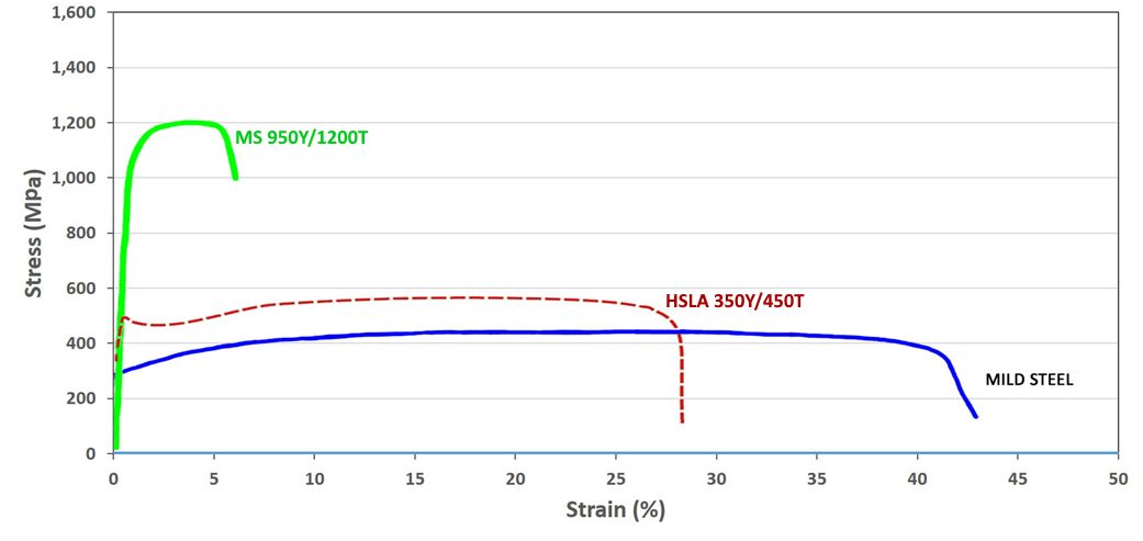
Figure 3: A comparison of stress strain curves for mild steel, HSLA 350/450, and MS 950/1200.

Figure 4: Engineering stress-strain curves for a series of MS steel grades.S-5 Sheet thicknesses: 1.8 mm to 2.0 mm.

Figure 5: True stress-strain curves for a series of MS steel grades.S-5 Sheet thicknesses: 1.8 mm to 2.0mm.
In addition to being produced directly at the steel mill, a martensitic microstructure also can be developed during the hot stamping of press hardening steels.
Examples of current production grades of martensitic steels and typical automotive applications include:
| MS 950/1200 |
Cross-members, side intrusion beams, bumper beams, bumper reinforcements |
| MS 1150/1400 |
Rocker outer, side intrusion beams, bumper beams, bumper reinforcements |
| MS 1250/1500 |
Side intrusion beams, bumper beams, bumper reinforcements |
Some of the specifications describing uncoated cold rolled 1st Generation martensite steel (MS) are included below, with the grades typically listed in order of increasing minimum tensile strength. Different specifications may exist which describe hot or cold rolled, uncoated or coated, or steels of different strengths. Many automakers have proprietary specifications which encompass their requirements.
- ASTM A980M, with Grades 130 [900], 160 [1100], 190 [1300], and 220 [1500]A-23
- VDA 239-100, with the terms CR860Y1100T-MS, CR1030Y1300T-MS, CR1220Y1500T-MS, and CR1350Y1700T-MSV-3
- SAE J2745, with terms Martensite (MS) 900T/700Y, 1100T/860Y, 1300T/1030Y, and 1500T/1200YS-18
Case Study: Using Martensitic Steels
as an Alternative to Press Hardening Steel
– Laboratory Evaluations
Martensitic steel grades provide a cold formed alternative to hot formed press hardening steels. Not all product shapes can be cold formed. For those shapes where forming at ambient temperatures is possible, design and process strategies must address the springback which comes with the high strength levels, as well as eliminate the risk of delayed fracture. The potential benefits associated with cold forming include lower energy costs, reduced carbon footprint, and improved cycle times compared with hot forming processes.
Highlighting product forms achievable in cold stamping, an automotive steel Product Applications Laboratory formed a Roof Center Reinforcement from 1.4 mm CR1200Y1470T-MS using conventional cold stamping rather than roll forming, Figure 6. Using cold stamping allows for the flexibility of considering different strategies when die processing which may result in reduced springback or incorporating part features not achievable with roll forming.

Figure 6: Roof Center Reinforcement cold stamped from CR1200Y1470T-MS martensitic steel.U-1
Cold stamping of martensitic steels is not limited to simpler shapes with gentle curvature. Shown in Figure 7 is a Center Pillar Outer, cold stamped using a tailor welded blank containing CR1200Y1470T-MS and CR320Y590T-DP as the upper and lower portion steels.U-1

Figure 7: Center Pillar Outer stamped at ambient temperature from a tailor welded blank containing 1470 MPa tensile strength martensitic steel.U-1
Another characteristic of martensitic steels is their high yield strength, which is associated with improved crash performance. In a laboratory environment, crash behavior is assessed with 3-point bending moments. A studyS-8 determined there was a correlation between sheet steel yield strength and the 3-point bending deformation of hat shaped parts. Based on a comparison of yield strength, Figure 8 shows that CR1200Y1470T-MS has similar performance to hot stamped PHS-CR1800T-MB and PHS-CR1900T-MB at the same thickness and exceeds the frequently used PHS-CR1500T-MB. For this reason, there may be the potential to reduce costs and even weight with a cold stamping approach, providing appropriate press, process, and die designs are used.

Figure 8: Effect of Yield Strength on Bending Moment. The right image shows the typical yield strength range of CR1030Y1300T-MS and CR1200Y1470T-MS as well as typical yield strength values of several Press Hardened Steels.S-8
Case Study: Martensitic Steels as an Alternative to
Press Hardening Steel – Automotive Production Examples
with Springback Mitigation Strategies
Recent years have seen some applications typically associated with press hardening steels transition to a cold stamped martensitic steel, CR1200Y1470T-MS. One such example is found in the third-generation Nissan B-segment hatchback (2020 start of production), which uses 1.2 mm thick CR1200Y1470T-MS as the material for the Second Cross Member Reinforcement.K-45
Using the carbon equivalent formula Ceq=C+Si/30+Mn/20+2P+4S K-45, the newly developed martensitic grade has a carbon equivalent value of 0.28, which is lower than the 0.35 associated with the conventional PHS grade of comparable tensile strength, 22MnB5 (PHS 1500T). The lower carbon equivalent value is expected to translate into easier welding conditions. Furthermore, conventional mechanical trimming and piercing equipment and techniques work with the cold formable martensitic grade, whereas parts formed from press hardening steels typically require laser trimming or other more costly approaches. An evaluation of delayed fracture found no evidence of this failure mode.
Figure 9 highlights this reinforcement, with its placement on the cross member and in the vehicle shown in red. The varying elevation of this part, combined with a non-uniform cross section at the outermost edges, help control springback, but makes roll forming significantly more challenging if that were the cold forming approach.

Figure 9: Cold-Stamped Martensitic Steel with 1500 MPa Tensile Strength used in the Nissan B-Segment Hatchback.K-57
Unbalanced stresses in stamped parts lead to several types of shape fixability issues collectively called springback. In hat shape wall sections, shape fixing beads sometimes referred to as stake beads (see Post Stretch information at this link) mitigate sidewall curl by imparting a tensile stress state on both the top and bottom sheet surfaces and increasing the rigidity. Springback control to limit flexing down the length of longitudinally curved parts requires a different technique. Here, the root cause is the stress difference between the tensile stress at the punch top and the compressive stress at the flange at bottom dead center of the press stroke. Figure 10 presents schematics of the stress distribution when the punch is located at bottom dead center of the press stroke, and the shape fixability issue after load removal.

Figure 10: Cold-Stamped Martensitic Steel With 1500 MPa Tensile Strength Used in the Lexus NXJ-24
A patented approach known as Stress Reverse Forming™T-44 improved dimensional accuracy in the second-generation Lexus NX (2021 start of production) center roof reinforcement, cold stamped from martensitic steel, CR1200Y1470T-MS.J-24 Figure 11 shows different views of this part.

Figure 11: Left Image: Springback Differences Exist in Coils at the Low and High End of the Strength Specification; Right Image: Stress Reverse Forming™ Process Reduces Sensitivity to Springback (Images Adapted from Citation T-29)
Stress Reverse Forming™T-44 uses the principles of the Bauschinger Effect to reverse the direction of the forming stresses during a restrike forming process to achieve a final part closer to the targeted dimensions.T-29 Parts processed with this two-step approach are first over-formed to a smaller radius of curvature than the final part shape. Removing the part from the tool after this first forming step results in the stress distribution seen in the left image in Figure 10. The unique aspect of this approach comes from the second forming step where the tool shape forces the punch top into slight compression while the lower flange is put into slight tension. The tool shape used in this stage contains a slightly greater radius of curvature than the targeted part shape. As shown in Citation T-29, this process appears to be equally effective at all steel strengths.
Without effective countermeasures, springback increases with part strength. Related to this is the springback difference between coils having strength at the lowest and highest ends of the acceptable property range. This can lead to substantial differences in springback between coils completely within specification. However, after using effective countermeasures such as Stress Reverse Forming™ described in Citation T-29, springback differences between coils are minimized, which leads to increased dimensional accuracy and more consistent stamping performance. This phenomenon is shown schematically in Figure 12. Furthermore, unlike conventional stamping approaches, the amount of springback in parts made with this approach does not increase with steel strength.

Figure 12: Left Image: Springback Differences Exist in Coils at the Low and High End of the Strength Specification; Right Image: Stress Reverse Forming™ Process Reduces Sensitivity to Springback (Images Adapted from Citation T-29)