Introduction PHS Grades with Tensile Strength Approximately 1500 MPa Grades with Higher Ductility PHS Grades Over 1500 MPa Other Steels for Press Hardening Process Stainless steels Medium-Mn steels Composite steels Introduction Press hardening steels (PHS) are...

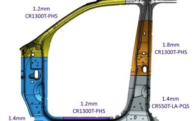
Press Hardening Steel Grades
read more