Press Hardening Steel Grades
- Introduction
- PHS Grades with Tensile Strength Approximately 1500 MPa
- Grades with Higher Ductility
- PHS Grades Over 1500 MPa
- Other Steels for Press Hardening Process
Introduction
Press hardening steels (PHS) are typically carbon-manganese-boron alloyed steels, specifically designed for hot forming process in the automotive industry. They are also commonly known as:
- Press Hardening Steels (PHS)
- Hot Press Forming Steels (HPF), a term more common in Asia
- Boron Steel: although the name may also refer to other steels, in automotive industry boron steel is typically used for PHS
- Hot Formed Steel (HF), a term more common in Europe.
Press Quenched Steels (PQS) are basically low-alloy steels, however they are specifically designed to have consistent mechanical properties after hot forming process, even at very wide cooling rate ranges.
The most common PHS grade is PHS1500. In Europe, this grade is commonly referred to as 22MnB5 or 1.5528. As received, it has ferritic-pearlitic microstructure and a yield strength between 300-600 MPa depending on the cold working. The tensile strength of as received steel can be expected to be between 450 and 750 MPa. Total elongation must be over a minimum of 10% (A80, with this minimum possibly different for A50 or A), but depending on coating type and thickness may well exceed 18% (A80), see Figure 1*. Thus, the grade can be cold formed to relatively complex geometries using certain methods and coatings. When hardened, it has a minimum yield strength of 950 MPa and tensile strength typically around 1300-1650 MPa, Figure 1.B-14 After hardening, the total elongation requirement changes from OEM to OEM. Some OEM’s require miniature specimens and ask for elongation of these specific specimens (such as A30) which cannot be comparable with A50 or A80. Typically about 3.5% to 6% minimum total elongation is required, depending on the thickness of the sheet and the type of the specimen (A30, A50 or A80) V-9.

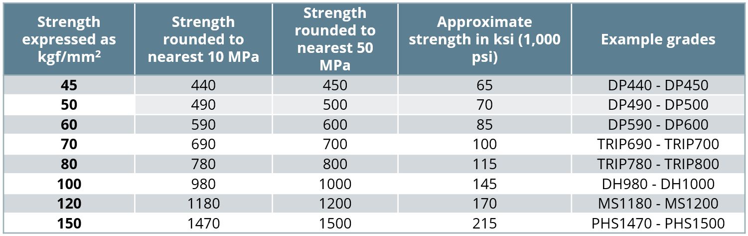
Figure 1: Stress-Strain Curves of PHS1500 before and after quenching * (re-created after U-9, O-8, B-18)
AHSS grades are almost always named after their “minimum” tensile strength. For example, DP590 is a steel with “minimum” tensile strength of 590 MPa. However, PHS and PQS grades may be named after their “typical” tensile strength level. Thus, PHS1500 may have a minimum tensile strength of 1300 MPa, as shown in Table 1. Some companies name PHS and PQS grades with their yield and tensile strength levels, such as PHS950Y1500T. It is also common in Europe to see this steel as PHS950Y1300T, and thus aiming for a minimum tensile strength of 1300 MPa after quenching. The numbers in the commercial names may also significantly differ from the minimum and/or typical. Thus, it is always important to check the specifications to see if the numbers used in the name are showing minimum or typical strength levels.
Table 1: List of common PQS and PHS grades Y-12, T-28, G-32, V-9, C-40, O-15
| Terminology | VDA239-500 Equivalent | Some Commercial Names (Listed Alphabetically by Steel Maker) |
Proof Strength (Rp0.2) [MPa] |
Tensile Strength (Rm or σUTS) [MPa] |
Elongation (A*) [%] |
VDA Bending Angle ** (α) [°] |
|
|---|---|---|---|---|---|---|---|
| PQS450 | 6Mn3 | CR500T-LA | Ductibor 450 B500HS Ultralume 500 PQS MBW 500 phs-ultraform 490 |
340-500 | 410-650 | ≥13 | >120 |
| PQS550 | 6Mn6 | CR600T-LA | Ductibor 500 B600HS MBW 600 |
370-600 | 550-800 | ≥12 | >85 |
| PHS1000 | 8MnB7 | CR1100T-MB | Ductibor 1000 B1000HS |
750-1000 | 950-1250 | ≥7 | >80 |
| PHS1200 | 12MnB6 | MBW 1200 | >75 | ||||
| 9MnCr | Coating free PHS 1200 | ~850 | ~1080 | ~6 | ~80 | ||
| PHS1500 | 22MnB5 | CR1500T-MB -DS / -IS | Usibor 1500 B1500HS Ultralume 1500 PHS HPF1470 MBW 1500 |
950-1250 | 1300-1650 | 5** | >50 |
| 20MnB8 | CR1500T-MB -PS | phs-directform | ~1050 ~1150PB |
~1500 | 6 | >70 | |
| 22MnSiB9-5 | CR1500T-MB -MS | – | 950-1250 | 1300-1700 | 5** | >40 | |
| PHS1700 | 20MnCr | – | Coating free PHS 1700 | ~1200PB | ~1700PB | ~9PB | ≥55PB |
| PHS1800 | 28MnB5 | – | Docol PHS1800 | ~1300 | ~1800 | ~6 | – |
| 30MnB5 | – | Sumiquench 1800 | ≥1250 | ≥1800 | ≥5 | ≥40 ≥55PB |
|
| PHS1900 | 34MnB5 | CR1900T-MB | MBW 1900 | ~1200 ~1300PB |
~1900 ~1850PB |
~4 ~4PB |
~50 ~55PB |
| PHS2000 | 37MnB4 | Usibor 2000 B2000HS HPF2000 Docol PHS2000 phs-ultraform 2000 |
≥1400PB | ≥1800PB | ≥5 | ≥45PB | |
| 34MnBV | – | – | 1360-1480 1500-1580PB |
2000-2100 1900-1970PB |
≥6 ≥6.5PB |
≥45 ≥50PB |
|
| * A is the elongation after break for a proportional specimen with L0 = 5,65 √S0 | |||||||
| ** The minimum requirement may be dependent on material thickness. | |||||||
| *** A50, ISO Type 1 elongation after break. | |||||||
| “~” is used for typical values | |||||||
| Superscript PB means after paint bake cycle. | |||||||
The PHS1500 name may also be used for the Zn-coated 20MnB8 or air hardenable 22MnSiB9-5 grades. The former is known as “direct forming with pre-cooling steel” and could be abbreviated as CR1500T-PS, PHS1500PS, PHSPS950Y1300T or similar (PS standing for Pre-Cooled Stamping). The latter grade is known as “multi-step hot forming steel” and could be abbreviated as, CR1500T-MS, PHS1500MS, PHSMS950Y1300T or similar (MS standing for Multi-Step Stamping).V-9
In the last decade, several steel makers introduced grades with higher carbon levels, leading to a tensile strength between 1800 MPa and 2000 MPa. Hydrogen induced cracking (HIC) and weldability limit applications of PHS1800, PHS1900 and PHS2000, with studies underway to develop practices which minimize or eliminate these limitations.
Lastly, there are higher energy absorbing, lower strength grades, which have improved ductility and bendability. These fall into two main groups: Press Quenched Steels (PQS) with approximate minimum tensile strength levels of 450 MPa and 550 MPa (noted as PQS450 and PQS550 in Figure 2) and higher ductility PHS grades with approximate minimum tensile strength levels of 1000 and 1200 MPa (shown as PHS1000 and PHS1200 in Figure 2).
Apart from these grades, other grades are suitable for press hardening. Several research groups and steel makers have offered special stainless-steel grades and recently developed Medium-Mn steels for hot stamping purposes. Also, one steel maker in Europe has developed a sandwich material by cladding PHS1500 with thin PQS450 layers on both sides.

Figure 2: Stress-strain curves of several PQS and PHS grades used in automotive industry,
after hot stamping for full hardening* (re-created after Citations B-18, L-28, Z-7, Y-12, W-28, F-19, G-30).
PHS Grades with Tensile Strength Approximately 1500 MPa
Hot stamping as we know it today was developed in 1970s in Sweden. The most used steel since then has been 22MnB5 with slight modifications. 22MnB5 means, approximately 0.22 wt-% C, approximately (5/4) = 1.25% wt-% Mn, and B alloying.
The automotive use of this steel started in 1984 with door beams. Until 2001, the automotive use of hot stamped components was limited to door and bumper beams, made from uncoated 22MnB5, in the fully hardened condition. By the end of the 1990s, Type 1 aluminized coating was developed to address scale formation. Since then, 22MnB5 + AlSi coating has been used extensively.B-14
Although some steel makers claim 22MnB5 as a standard material, it is not listed in any international or regional (i.e., European, Asian, or American) standard. Only a similar 20MnB5 is listed in EN 10083-3.T-26, E-3 The acceptable range of chemical composition for 22MnB5 is given in Table 2.S-64, V-9
VDA239-500, a material recommendation from Verband Der Automotbilindustrie E.V. (VDA), is an attempt to further standardize hot stamping materials. The document was first published in December 2021. According to this standard, 22MnB5 may be delivered coated or uncoated, hot or cold rolled. Depending on these parameters, as-delivered mechanical properties may differ significantly. Steels for the indirect process, for example, has to have a higher minimum total elongation to ensure cold formability.V-9 Figure 1 shows generic stress-strain curves, which may vary significantly depending on the coating and selected press hardening process.
For 22MnB5 to reach its high strength after quenching, it must be austenitized first. During heating, ferrite begins to transform to austenite at “lower transformation temperature” known as Ac1. The temperature at which the ferrite-to-austenite transformation is complete is called “upper transformation temperature,” abbreviated as Ac3. Both Ac1 and Ac3 are dependent on the heating rate and the exact chemical composition of the alloy in question. The upper transformation temperature (Ac3) for 22MnB5 is approximately 835-890 °C.D-21, H-30Austenite transforms to other microstructures as the steel is cooled. The microstructures produced from this transformation depends on the cooling rate, as seen in the continuous-cooling-transformation (CCT) curve in Figure 3. Achieving the “fully hardened” condition in PHS grades requires an almost fully martensitic microstructure. Avoiding transformation to other phases requires cooling rates exceeding a minimum threshold, called the “critical cooling rate,” which for 22MnB5 is 27 °C/s. For energy absorbing applications, there are also tailored parts with “soft zones”. In these soft zones, areas of interest will be intentionally made with other microstructures to ensure higher energy absorption.B-14

Figure 3: Continuous Cooling Transformation (CCT) curve for 22MnB5
(Published in Citation B-19, re-created after Citations M-25, V-10).
Once the parts are hot stamped and quenched over the critical cooling rate, they typically have a yield strength of 950-1200 MPa and an ultimate tensile strength between 1300 and 1700 MPa. Their hardness level is typically between 470 and 510 HV, depending on the testing methods.B-14
Once automotive parts are stamped, they are then joined to the car body in body shop. The fully assembled body known as the Body-in-White (BIW) with doors and closures, is then moved to the paint shop. Once the car is coated and painted, the BIW passes through a furnace to cure the paint. The time and temperature for this operation is called the paint bake cycle. Although the temperature and duration may be different from plant to plant, it is typically close to 170 °C for 20 minutes. Most automotive body components made from cold or hot formed steels and some aluminum grades may experience an increase in their yield strength after paint baking. The so-called Bake-Hardening Index (yield strength increase due to paint baking) is calculated based on EN 10325 or OEM standards.
In Figure 4, press hardened 22MnB5 is shown in the red curve. In this particular example, the proof strength was found to be approximately 1180 MPa. After processing through the standard 170 °C – 20 minutes bake hardening cycle, the proof strength increases to 1280 MPa (shown in the black curve).B-18 Most studies show a bake hardening increase of 100 MPa or more with press hardened 22MnB5 in industrial conditions.B-18, J-17, C-17

Figure 4: Bake hardening effect on press hardened 22MnB5.
Named as BH0, is shown since there is no cold deformation pre-strain. (re-created after Citation B-18).
There are two modified versions of the 22MnB5 recently offered by several steel makers: 20MnB8 and 22MnSiB9-5. Both grades have higher Mn and Si compared to 22MnB5, as shown in Table 3.
| [wt. %] | C | Mn | B | Si |
|---|---|---|---|---|
| 22MnB5 | 0.20-0.25 | 1.10-1.50 | 0.0020-0.0050 | ≤0.50 |
| 20MnB8 | 0.17-0.23 | 1.70-2.50 | 0.0020-0.0050 | ≤0.50 |
| 22MnSiB9-5 | 0.20-0.25 | 2.00-2.40 | 0.0015-0.0040 | 1.00-1.40 |
Both of these relatively recent grades are designed for Zn-based coatings and are designed for different process routes. For these reasons, many existing hot stamping lines would require some modifications to accommodate these grades.
20MnB8 has been designed for a “direct process with pre-cooling”. The main idea is to solidify the Zn coating before forming, eliminating the possibility that liquid zinc fills in the micro-cracks on the formed base metal surface, which in turn eliminates the risk of Liquid Metal Embrittlement (LME). The chemistry is modified such that the phase transformations occur later than 22MnB5. The critical cooling rate of 20MnB8 is approximately 10 °C/s. This allows the part to be transferred from the pre-cooling stage to the forming die without any phase transformations. As press hardened, the material has a typical yield strength of 1050 MPa and 1500 MPa typical tensile strength. Once bake hardened (170 °C, 20 minutes), yield strength may exceed 1100 MPa.K-22, V-24 This steel may be referred to as PHS950Y1300T-PS (Press Hardening Steel with minimum 950 MPa Yield, minimum 1300 MPa Tensile strength, for Pre-cooled Stamping) or CR1500T-MB-PS (Cold Rolled, typical 1500 MPa Tensile strength, Manganese-Boron alloyed, Pre-cooled Stamping) V-9.
22MnSiB9-5 has been developed for a transfer press process, named as “multi-step”. As quenched, the material has similar mechanical properties with 22MnB5 (Figure 5). As of 2020, there is at least one automotive part mass produced with this technology and is applied to a compact car in Germany.G-27 Although the critical cooling rate is listed as 5 °C/s, even at a cooling rate of 1 °C/s, hardness over 450HV can be achieved, as shown in Figure 6.H-27 This allows the material to be “air-hardenable” and thus, can handle a transfer press operation (hence the name multi-step) in a servo press. This material is also available with Zn coating.B-15 This steel may be referred to as PHS950Y1300T-MS (Press Hardening Steel with minimum 950 MPa Yield, minimum 1300 MPa Tensile strength, for Multi-Step process) or CR1500T-MB-MS (Cold Rolled, 1500 MPa typical Tensile strength, Manganese-Boron alloyed, Multi-Step Process).

Figure 5: Engineering stress-strain curves of 1500 MPa level grades (re-created after Citations B-18, G-29, K-22)

Figure 6: Critical cooling rates of 1500 MPa level press hardening steels (re-created after Citations K-22, H-31, H-27)
Grades with Higher Ductility
Press hardened parts are extremely strong, but cannot absorb much energy. Thus, they are mostly used where intrusion resistance is required. However, newer materials for hot stamping have been developed which have higher elongation (ductility) compared to the most common 22MnB5. These materials can be used in parts where energy absorption is required. These higher energy absorbing, lower strength grades fall into two groups, as shown in Figure 7. Those at the lower strength level are commonly referred to as “Press Quenched Steels” (PQS). The products having higher strength in Figure 7 are press hardening steels since they contain boron and do increase in strength from the quenching operation. The properties listed are after the hot stamping process.
- Typical tensile strength levels of 450 and 550 MPa, with minimum 12% total elongation, listed as PQS450 and PQS550.
- 950 to 1250 MPa tensile strength level and minimum 5% total elongation, listed as PHS1000 and PHS1200.

Figure 7: Stress-strain curves of several PQS and PHS grades used in automotive industry, after hot stamping for full hardening* (re-created after Citations B-18, Y-12).
Currently none of these grades are standardized. Most steel producers have their own nomination and standard, as summarized in Table 4. There is a document by German Association of Automotive Industry (Verband der Automobilindustrie, VDA), which specifies the incoming properties of these grades. In the standard, VDA239-500, the steel shown here as PQS450 is listed as CR500T-LA (Cold Rolled, 500 MPa typical Tensile strength, Low Alloyed). Similarly, PQS550 in this document is listed as CR600T-LA. PHS1000 and PHS1200 in this document is similar to VDA239-500’s CR1100T-MB (Cold Rolled, MPa typical Tensile strength, Manganese-Boron alloyed).V-9 Some OEMs may prefer to name these grades with respect to their yield and tensile strength together, as listed in Table 4.
Higher Ductility grade names are based on their properties and
terminology is derived from a possible chemistry or OEM description.
The properties listed here encompass those presented in multiple sources
and may or may not be associated with any one specific commercial grade.Y-12, T-28, G-32, M-71, S-115
| Terminology | VDA 239-500 Equivalent |
OEM Nomenclature | Proof Strength (Rp0.2) [MPa] |
Tensile Strength (Rm or σUTS) [MPa] |
Elongation (A*) [%] |
VDA Bending Angle ** (α) [°] |
|
|---|---|---|---|---|---|---|---|
| PQS450 | 6Mn3 | CR500T-LA | PQS340Y410T PSC340Y460T |
340-500 | 410-650 | 13 | >120 |
| PQS550 | 6Mn6 | CR600T-LA | HS550T/370Y-MP PQS370Y550T PSC370Y550T |
370-600 | 550-800 | 12 | >85 |
| PHS1000 | 8MnB7 | CR1100T-MB | HS1000T/800Y-MP PHS800Y1000T PSC750Y950T |
750-1000 | 950-1250 | 7 | >80 |
| PHS1200 | 12MnB6 | >75 | |||||
| 9MnCr | ~850 | ~1080 | ~6 | ~80 | |||
Higher energy absorbing grades have been under development at least since 2002. In the earliest studies, PHS 1200 was planned.R-11 Between 2007 and 2009, three new cars were introduced in Europe, having improved “energy absorbing” capacity in their hot stamped components. VW Tiguan (2007-2016) and Audi A5 Sportback (2009-2016) had soft zones in their B-pillars (Figure 8B and C). Intentionally reducing the cooling rate in these soft zone areas produces microstructures having higher elongations. In the Audi A4 (2008-2016) a total of three laser welded tailored blanks were hot stamped. The soft areas of the A4 B-pillars were made of HX340LAD+AS (HSLA steel, with AlSi coating, as delivered, min yield strength = 340 MPa, tensile strength = 410-510 MPa) as shown in Figure 8A. After the hot stamping process, HX340LAD likely had a tensile strength between 490 and 560 MPaS-65, H-32, B-20, D-22, putting it in the range of PQS450 (see Table 3). Note that these were not the only cars to have tailored hot stamped components during that time.

Figure 8: Earliest energy absorbing hot stamped B-pillars: (A) Audi A4 (2008-2016) had a laser welded tailored blank with HSLA material; (B) VW Tiguan (2007-2015) and (C) Audi A5 Sportback (2009-2016) had soft zones in their B-pillars (re-created after Citations H-32, B-20, D-22).
A 2012 studyK-25 showed that a laser welded tailored B-Pillar with 340 MPa yield strength HSLA and 22MnB5 had the best energy absorbing capacity in drop tower tests, compared to a tailored (part with a ductile soft-zone) or a monolithic part, Figure 9. As HSLA is not designed for hot stamping, most HSLA grades may have very high scatter in the final properties after hot stamping depending on the local cooling rate. Although the overall part may be cooled at an average 40 to 60 °C/s, at local spots the cooling rate may be over 80 °C/s. PQS grades are developed to have stable mechanical properties after a conventional hot stamping process, in which high local cooling rates may be possible.M-26, G-31, T-27

Figure 9: Energy absorbing capacity of B-pillars increase significantly with soft zones or laser welded tailored blank with ductile material (re-created after Citation K-25).
Conventional High-Strength and Advanced High-Strength Steels are not designed for hot stamping process. HSLA340 (minimum yield strength, as delivered) and CMn440 steel (Carbon-manganese alloyed, minimum 440 MPa tensile strength at delivery) may be softer than their as-delivered condition when heated over austenitization temperature and slowly cooled at 15 °C/s cooling rate. Furthermore, if the local cooling rate is over 60 to 80 °C/s, a significant increase in hardness (see Figure 10) and sharp decrease in elongation may be observed.D-22, T-27 PQS550 and PHS1000 have relatively more stable mechanical properties at high cooling rates.S-116, S117

Figure 10: Vickers hardness variation of several cold stamping steels after austenitization and at different cooling rates (re-created using data from Citations D-22, S-116, and S117).
PQS grades have been in use at latest since 2014. One of the earliest cars to announce using PQS450 was VolvoXC90. There are six components (three right + three left), laser welded tailored blanks with PQS450, as shown Figure 11.L-29 Since then, many carmakers started to use PQS450 or PQS550 in their car bodies. These include:
- Fiat 500X: Patchwork supported, laser welded tailored rear side member with PQS450 in crush zonesD-23,
- Fiat Tipo (Hatchback and Station Wagon versions): similar rear side member with PQS450B-14,
- Renault Scenic 3: laser welded tailored B-pillar with PQS550 in the lower sectionF-19,
- Chrysler Pacifica: five-piece front door ring with PQS550 in the lower section of the B-Pillar areaT-29, and
- Chrysler Ram: six-piece front door ring with PQS550 in the lower section of the B-Pillar area.R-3

Figure 11: Use of laser welded tailored blanks with PQS and PHS grades in 2nd generation Volvo XC90 (re-created after Citation L-29).
Several car makers use PQS grades to facilitate joining of components. The B-Pillar of the Jaguar I-PACE electric SUV is made of PQS450, with a PHS1500 patch that is spot welded before hot stamping, creating the patchwork blank shown in Figure 12a.B-21 Early PQS applications involved a laser welded tailored blank with PHS 1500. Since 2014, Mercedes hot stamped PQS550 blanks not combined with PHS1500. Figure 12b shows such components on the Mercedes C-Class.K-26

Figure 12: Recent PQS applications: (a) 2018 Jaguar I-PACE uses a patchwork B-pillar with PQS450 master blank and PHS1500 patchB-21, (b) 2014 Mercedes C-Class has a number of PQS550 components that are not laser welded to PHS1500.K-26
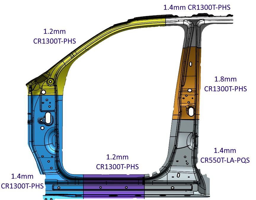
PHS1000 is also used for energy absorbing purposes, as well as facilitating weldability. Figure 13 shows some of the recent examples of PHS1000 usage.
![Figure 13: PHS1000 applications: (left) Door ring of Tesla Model Y (SOP 2020) [Citations B-79 and A-84], (right) Door ring of Voyah Dream (SOP 2022). [Citation H-70].](https://ahssinsights.org/wp-content/uploads/2025/11/PHS-Grade-RevFig-13.svg)
Figure 13: PHS1000 applications: (a) Door ring of Tesla Model Y (SOP 2020)B-79,A-84; (b) Door ring of Voyah Dream (SOP 2022)H-70.
Whereas the microstructure of PHS with a targeted strength of 1500 MPa is martensite, the microstructure of PQS grades contain a combination of ferrite, martensite, and bainite. This indicates that these sections require different thermal profiles.
A publication from 2023 compares the effects of two thermal profiles on the properties of a PQS grade with a mating PHS 1500 grade, as indicated in Table 5. There is little effect on the PHS 1500 properties, but the second profile shows better ductility and a smaller thickness of the Al-Si alloy layer – both of which are preferred.L-74
| Process | HC370 / 550HS + AS | HC950 / 1300HS + AS | ||||||
|---|---|---|---|---|---|---|---|---|
| Yield Strength (MPa) |
Tensile Strength (MPa) |
Elongation (%) |
Al-Si Layer Thickness (µm) |
Yield Strength (MPa) |
Tensile Strength (MPa) |
Elongation (%) |
Al-Si Layer Thickness (µm) |
|
| 1 | 509 | 640 | 14.00 | 14 | 1189 | 1500 | 6.74 | 18 |
| 2 | 365 | 606 | 24.72 | 8 | 1180 | 1492 | 7.72 | 8 |
PHS Grades over 1500 MPa
The most commonly used press hardening steels have 1500 MPa tensile strength, but are not the only optionsR-11, with 4 levels between 1700 and 2000 MPa tensile strength available or in development as shown in Figure 14. Hydrogen induced cracking (HIC) and weldability problems limit widespread use in automotive applications, with studies underway to develop practices which minimize or eliminate these limitations.

Figure 14: PHS grades over 1500 MPa tensile strength, compared with the common PHS1500
(re-created after Citations B-18, W-28, Z-7, L-30, L-28, B-14, O-15).
Mazda Motor Corporation was the first vehicle manufacturer to use higher strength boron steels, with the 2011 CX-5 using 1,800MPa tensile strength reinforcements in front and rear bumpers, Figure 15. According to Mazda, the new material saved 4.8 kg per vehicle. The chemistry of the steel is Nb modified 30MnB5.H-33, M-28 Figure 16 shows the comparison of bumper beams with PHS1500 and PHS1800. With the higher strength material, it was possible to save 12.5% weight with equal performance.H-33

Figure 15: Bumper beam reinforcements of Mazda CX-5 (SOP 2011) are the first automotive applications
of higher strength (>1500 MPa) press hardening steels.M-28

Figure 16: Performance comparison of bumper beams with PHS1500 and PHS1800 (re-created after H-33).
PHS 1800 is also used in the 2022 Genesis Electrified G80 (G80EV) and the new G90, both from Hyundai Motor. A specialized method lowering the heating furnace temperature by more than 50℃ limits the penetration of hydrogen into the blanks, minimizing the risk of hydrogen embrittlement. L-64.
MBW 1900 is the commercial name for a press hardening steel with 1900 MPa tensile strength. An MBW 1900 B-pillar with correct properties can save 22% weight compared to 590DP and yet may cost 9% less than the original Dual-Phase design.H-34 Ford had also demonstrated that by using MBW 1900 instead of PHS 1500, a further 15% weight could be saved.L-30 Since 2019, VW’s electric vehicle ID.3 has two seat crossbeams made of MBW 1900 steel, as seen in Figure 15.L-31 The components are part of MEB platform (Modularer E-Antriebs-Baukasten – modular electric-drive toolkit) and may be used in other VW Group EVs. MBW 1900 can be ordered as uncoated or AS Pro coated (Aluminum-Silicon with Magnesium).T-50

Figure 17: Underbody of VW ID3 (part of MEB platform).L-31
USIBOR 2000 is the commercial name given to a steel grade similar to 37MnB4 with an AlSi (AS) coating. Here, it will be described as PHS2000+AS.. Final properties are expected only after paint baking cycle, and the parts made with this grade may be brittle before paint bake.B-32 In June 2020, Chinese Great Wall Motors started using PHS2000+AS in the Haval H6 SUV.V-12
Since 2023, PHS2000+AS has been used in the A-pillar of Stellantis’ Maserati Grecale SUV. The design allowed downgauging from 1.4 mm PHS1500 to 1.3 mm PHS2000 with comparable crash performance. This weight savings corresponds to 0.8 kg per car. B-80 In late 2023, Toyota introduced the 2nd generation C-HR. This vehicle has a 2 GPa B-pillar with no additional reinforcement. The previous generation had PHS1500 B-pillar with a secondary reinforcement also from PHS1500. The new design not only saved 3.5 kg per vehicle, but also saved cost.A-83 See Figure 18 for these applications. PHS2000+AS is also used as a patch in the door ring of Voyah Dream, as pictured in Figure 13b.H-70

Figure 18: PHS2000+AS applications: (a) A-pillar of Maserati GrecaleB-80 and (b) B-pillar of Toyota C-HR.D-45
HPF 2000, another commercial name, is used in a number of component-based examples, and also in the Renault EOLAB concept car.L-28, R-12 An 1800 MPa grade is under development.P-22 Docol PHS 1800, a commercial grade approximating 30MnB5, has been in production, with Docol PHS 2000 in development.S-66 PHS-ultraform 2000, a commercial name for a Zn (GI) coated blank, is suited for the indirect process.V-11
General Motors China, together with several still mills across the country, have developed two new PHS grades: PHS 1700 (20MnCr) and PHS2000 (34MnBV). 20MnCr uses Cr alloying to improve hardenability and oxidation resistance. This grade can be hot formed without a coating, and thus named as coating free PHS (CFPHS). The furnace has to be conditioned with N2 gas. The final part has high corrosion resistance, approximately 9% total elongation (see Figure 12) and high bendability (see Table 4). 34MnBV on the other hand, has a thin AlSi coating (20g/m2 on each side). Compared with the typical thickness of AlSi coatings (30 to 75 g/m2 on each side), thinner coatings are preferred for bendability (see Table 6).W-28 More information about these oxidation resistant PHS grades, as well as a 1200 MPa version intended for applications benefiting from enhanced crash energy absorption, can be found in Citation L-60.
A research team, including Volkswagen Group Innovation, have recently developed 37SiB6 steel. They named the grade as SIBORA (Silicon – Boron alloyed steel with Retained Austenite). The grade when hot stamped has a yield strength of approximately 1600 MPa and a tensile strength of 2050 MPa. The microstructure has 3-5% retained austenite, giving it a very high total elongation of 10% (A80, measured on an ISO Type 2, 20×80 tensile specimen). The research team also developed a process called BQP, Bainitizing, Quenching and Partitioning. With this method, several strength-ductility levels can be achieved from the same alloy.O-15 BQP process is explained in the next section under Single Alloy Concepts.

Figure 19: 37SiB6, also known as SIBORA, before and after hot stamping (re-created after O-15).
Single Alloy Concepts
In 2021, a research group from China came up with the Uni-Steel proposal, where the whole car body can be built by using a single alloy concept. The material is similar to 22MnB5 but has higher Cr and Si content, and some Nb alloying. When hot stamped, the material would have a yield strength of 1400 MPa (typical) and tensile strength of 1600 MPa (thus named as PHS1600 in Figure 20a). When different heat treatments are applied, the material can be as soft as 420 MPa yield / 600 MPa tensile. This is named as HSLA in Figure 20a. The authors specified 6 different process routes, ending up 6 different material specs as shown in Figure 20. There was also a car body design made of single alloy, different strength levels, as shown in Figure 20c.L-68

Figure 20: Uni-Steel concept: (a) Different variants, b) their engineering stress-strain curves, (c) a concept BIW design using these variants (re-created after L-68).
SIBORA, or 37SiB6, can also be processed using a Bainitizing, Quenching and Partitioning (BQP) process to generate different variants. In the BQP process, the sheet metal is first austenitized around 930°C and then rapidly cooled to bainitizing temperature, between 360 and 460°C, as seen in Figure 21a. The bainitizing temperature and time affect tensile properties. By tailoring both variables, tensile strength can be altered between 1150 and 2050 MPa, total elongation can be altered between 19% and 9%, Figure 21b.O-15

Figure 21: (a) Schematic time-temperature curve of BQP process, (b) several variants of SIBORA (37SiB6) using hot stamping and BQP process routes (both re-created after L-15).
Other Steels for Press Hardening Process
In recent years, many new steel grades are under evaluation for use with the press hardening process. Few, if any, have reached mass production, and are instead in the research and development phase. These grades include:
Stainless Steels
Studies of press hardening of stainless steels primarily focus on martensitic grades (i.e., AISI SS400 series).M-36, H-42, B-40, M-37, F-30 As seen in Figure 22, martensitic stainless steels may have higher formability at elevated temperatures, compared to PHS1500 (22MnB5). Other advantages of stainless steels are:
- No scale formation at high temperatures, no controlled atmosphere is required in the furnaceL-70
- better corrosion resistance of the final partM-37,
- allow higher heating rates (i.e., induction heating), since the blanks are uncoated (no rules for coating diffusion) F-30,L-70
- possibility of air hardening – allowing the multi-step process — as seen in Figure 23a H-42,
- high cold formability – allowing indirect process – as seen in Figure 23b.M-37
Disadvantages include (a) higher material cost, (b) higher furnace temperature (up to around 1050-1150 °C – see Table 6), and (c) high Cr content would significantly reduce weldability.M-37, F-30 As of 2025, there are only two commercially available stainless steel grades specifically developed for press hardening process.A-85 At least one more stainless steel maker have also developed a grade for hot stamping (420C), however, it was not listed in their commercial offerings, as of 2025.

Figure 22: Tensile strength and total elongation variation with temperature of
(a) PHS1500 = 22MnB5M-38 and (b) martensitic stainless steel.M-36

Figure 23: (a) Critical cooling rate comparison of 22MnB5 and AISI SS410 (re-created after Citation H-42, (b) Room temperature forming limit curve comparison of DP600 and modified AISI SS410 (re-created after Citation M-37.
Final mechanical properties of stainless steels after press hardening process are typically superior to 22MnB5, in terms of elongation and energy absorbing capacity. Figure 24 illustrates engineering stress-strain curves of the two commercially available grades (1.6065 and 1.4064), and compares them with the 22MnB5 and a duplex stainless steel (Austenite + Martensite after press hardening and tempering). The duplex grade was also developed by a stainless steel maker, but is still not commercially available. These grades may also have bake hardening effect, abbreviated as BH0, as there will be no cold deformation.B-40, M-37, F-30

Figure 24: Engineering Stress-Strain curves of press hardened stainless steels, compared with 22MnB5
(re-created after Citations B-40, M-37, F-30, B-41).
| Terminology | Furnace Temperature (Theat) [°C] |
Secondary Tempering |
Proof Strength (Rp0.2) [MPa] |
Tensile Strength (Rm or σUTS) [MPa] |
Elongation (A*) [%] |
VDA Bending Angle ** (α) [°] |
|
|---|---|---|---|---|---|---|---|
| 1.4034 | 420C | 1150 | 400°C, 5 min. | 1100-1300 | 1700-1850 | 12-16 | – |
| 1.4003 | 410L | 950 | – | ~830 | ~1020 | ~7 | – |
| 1.4021 | 420 | 1030 | – | ~1125 | ~1750 | ~5 | – |
| 1.4021 | 420 | 1030 | 600°C, 10 min. | ~930 | ~1090 | ~9 | – |
| 1.6065 | Modified 410 | 1050 | – | ~1200 | ~1600 | ≥7 | ~70 |
| 1.6065 | Modified 410 | 950 | – | ~870 | ~1130 | ≥10 | ~100 |
| ** VDA Bending angle may depend on thickness and method of measurement (α0 or αM) | |||||||
Other than these, there is also a study where 27MnB5 was cladded with AISI 304 on both top and bottom. This study is explained in detail in Composite Steels section.
Medium-Mn Steels
Medium-Mn steels typically contain 3 to 12 weight-% manganese alloying.D-27, H-30, S-80, R-16, K-35 Although these steels were originally designed for cold stamping applications, there are numerous studies related to using them in the press hardening process as well.H-30 Several advantages of medium-Mn steels in press hardening are:
- Austenitization temperature may be significantly lower than compared to 22MnB5, as indicated in Figure 19.H-30, S-80 Thus, using medium-Mn steels may save energy in heating process.M-39 Lower heating temperature may also help reducing the liquid-metal embrittlement risk of Zn-coated blanks. It also may reduce oxidation and decarburization of uncoated blanks.S-80
- Martensitic transformation can occur at low cooling rates. Simpler dies could be used with less or no cooling channels. In some grades, air hardening may be possible. Thus, multi-step process could be employed.S-80, B-14
- Some retained austenite may be present at the final part, which can enhance the elongation, through the TRIP effect. This, in turn, improves toughness significantly.S-80, B-14

Figure 25: Effect of Mn content on equilibrium transformation temperatures (re-created after Citations H-30, B-14).
The change in transformation temperatures with Mn-alloying was calculated using ThermoCalc software.H-30 As seen in Figure 25, as Mn alloying is increased, austenitization temperatures are lowered.H-30 For typical 22MnB5 stamping containing 1.1 to 1.5 % Mn, furnace temperature is typically set at 930 °C in mass production. The multi-step material 22MnSiB9-5 has slightly higher Mn levels (2.0 to 2.4 %), so the furnace temperature could be reduced to 890 °C. As also indicated in Table 6, the furnace temperature could be further lowered to 650°C in hot forming of medium-Mn steels.
A study in the EU showed that if the maximum furnace temperature is 930 °C, which is common for 22MnB5, natural gas consumption will be around 32 m3/hr. In the study, two new medium-Mn steels were developed, one with 3 wt.% Mn and the other with 5 wt% Mn. These grades had lower austenitization temperature, and the maximum furnace set temperature could be reduced to 808 °C and 785 °C, respectively. Experimental data shows that at 808 °C natural gas consumption was reduced to 19 m3/hr, and at 785 °C to 17 m3/hr.M-39 In Figure 26, experimental data is plotted with a curve fit. Based on this model, it was estimated that by using 22MnSiB9-5, furnace gas consumption may be reduced by 15%.

Figure 26: Effect of maximum furnace set temperature (at the highest temperature furnace zone) on natural gas consumption (raw data from Citation M-39).
Lower heating temperature of medium-Mn steels may also help reducing the liquid-metal embrittlement risk of Zn-coated blanks. It also may reduce oxidation and decarburization of uncoated blanks.S-80
Medium-Mn steels may have high yield-point elongation (YPE), with reports of more than 5% after hot stamping. Mechanical properties may be sensitive to small changes in temperature profile. As seen in Figure 27, all studies with medium-Mn steel have a unique stress-strain curve after press hardening. This can be explained by:
- differences in the chemistry,
- thermomechanical history of the sheet prior to hot stamping,
- heating rate, heating temperature (see Figure 28), and soaking time, and
- cooling rate,S-80 and
- secondary heat treatments such as quenching and partitioning.W-41
In a recent study, various heating temperatures were examined. As seen in Figure 28, both the stress-strain behavior and the phase fractions change significantly with heating temperature.W-42

Figure 27: Engineering Stress-Strain curves of several press hardened medium-Mn steels, compared with 22MnB5. See Table 7 for an explanation of each tested material (re-created after Citations S-80,L-37, W-30, L-38).
![Figure 28: Engineering stress-strain curves of 4% Mn steel, heated to different temperature (760. 800 and 840°C). Phase fractions are also affected by the heating temperature (re-created after [CITATION 20]).](https://ahssinsights.org/wp-content/uploads/2025/09/PHS-Grades-Figure-28.svg)
Figure 28: Engineering stress-strain curves of 4% Mn steel, heated to different temperature (760. 800 and 840°C).
Phase fractions are also affected by the heating temperature (re-created after W-42).
Typical values are indicated with “~”.
Toughness is calculated as the area under the engineering stress-strain curve.
Items 4 and 5 also were annealed at different temperatures and therefore have different thermomechanical history.
Note that these grades are not commercially available.
Based on Citations L-38, W-30, L-37, S-80, and W-42.
| Number (Figs. 27 and 28)
Chemistry and Reference |
Furnace Temperature (Theat) [°C] |
Proof Strength (Rp0.2) [MPa] |
Tensile Strength (Rm or σUTS) [MPa] |
Elongation (A*) [%] |
Toughness [GPa %El.] |
|---|---|---|---|---|---|
| 1: 5 Mn, 0.1 C, 0.23 Si, 0.03 Al L-38 | 800 | 1050 | 1520 | 11 | 14.9 |
| 2: 6 Mn, 0.2 C, 1.25 Al, Mo, Nb W-30 | 700 | 780 | 1430-1460 | 22-26 | 12.2 |
| 3: 7 Mn, 0.2 C, 0.3 Cr, 0.38 Si, 0.23 Al L-37 | 700 | 1420 | 1700 | 11 | 18.6 |
| 4: 9.76 Mn, 0.16 C, 1.37 Al, 0.19 Si, 0.0018 S S-80 | 700 | 585 | 1450 | 17 | 18.4 |
| 5: 9.76 Mn, 0.16 C, 1.37 Al, 0.19 Si, 0.0018 S S-80 | 650 | 1060 | 1150 | 44 | 46 |
| 6: 3.84 Mn, 0.27 C, 1.63 Al, 0.62 Si W-42 | 840 | 1060 | 1385 | 14 | 15.7 |
| 6: 3.84 Mn, 0.27 C, 1.63 Al, 0.62 Si W-42 | 800 | 840 | 1535 | 9 | 18.6 |
| 6: 3.84 Mn, 0.27 C, 1.63 Al, 0.62 Si W-42 | 760 | 565 | 1680 | 6 | 25.8 |
Composite Steels
TriBond ® is the name given to a family of steel composites.T-32 Here, three slabs (one core material (60 to 80% of the thickness) and two cladding layers) are surface prepared, stacked on top of each other, and welded around the edges. The stack is hot rolled to thickness. Cold rolling could also be applied. Initially, TriBond ® was designed for wear-resistant cladding and ductile core materials.
The original design was optimized for hot stamping.B-14 The core material, where bending strains are lower than the outer layers, is made from generic 22MnB5 (PHS1500). Outer layers are made with PQS450. The stack is cold rolled, annealed and AlSi coated.Z-9 Two grades are developed, differing by the thickness distribution between the layers, as shown in Figure 29.R-14

Figure 29: Sample microsections of the conventional hot stamping grade PHS1500+AS, the high strength composite Tribond® 1400 and the high energy absorbing composite Tribond® 1200. The Tribond® 1200 microsection is experimental and is taken from Citation R-14. The other two images are renditions created by the author for explanation purposes. (re-created after Citations R-14, R-15)
Total elongation of the composite steel is not improved, compared to PHS1500, as shown in Figure 30. The main advantage of the composite steels is their higher bendability, as seen in Table 8. Crashboxes, front and rear rails, seat crossmembers and similar components experience axial crush loading in the event of a crash. In axial crush, Tribond® 1200 saved 15% weight compared to DP780 (CR440Y780T-DP). The bending loading mode effects B-pillars, bumper beams, rocker (sill) reinforcements, side impact door beams, and similar components during a crash. In this bending mode, Tribond® 1400 saved 8 to 10% weight compared to regular PHS1500. Lightweighting cost with Tribond® 1400 was calculated as €1.50/kgsaved.G-37, P-26

Figure 30: Engineering Stress-Strain curves of core layer, outer layer and the composite steel (re-created after Citation P-26).
In 2021, two German universities developed a similar composite steel, this time the core was 27MnCrB5-2 with stainless steel 1.4301 (AISI 304) claddings at the top and bottom. The details of the study is summarized in Table 8.K-63
Typical values are indicated with “~”. (Table re-created after Citations
B-14 and K-63.)
| Grade | Composition through thickness |
Proof Strength (Rp0.2) [MPa] |
Tensile Strength (Rm or σUTS) [MPa] |
Elongation (A80) [%] |
Bending angle (α) [°] |
|---|---|---|---|---|---|
| PQS450 | 100% PQS450 | ~400 | ~550 | ~17 | 140-155 |
| Tribond ® 1200 | 20% PQS450 60% PHS1500 20% PQS450 |
≥730 | ≥1100 | ≥5 | ≥135 |
| Tribond ® 1400 | 10% PQS450 80% PHS1500 10% PQS450 |
≥890 | ≥1300 | ≥5 | ≥75 |
| PHS1500 | 100% PHS1500 | ≥1000 | ≥1400 | ≥5 | ≥55 |
| AISI304 | 100% AISI 304 | ~300 | ~640 | – | – |
| Composite Steel | 12.5% AISI 304 75% 27MnCrB5-2 12.5% AISI304 |
~820 | 1300 | – | – |
| 27MnCrB5-2 | 100% ‘7MnCrB5-2 | ~1020 | ~1500 | – | – |
* Graphs in this article are for information purposes only. Production materials may have different curves. Consult the Certified Mill Test Report and/or characterize your current material with an appropriate test (such as a tensile, bending, hole expansion, or crash test) test to get the material data pertaining to your current stock.
For more information on Press Hardened Steels, see these pages:
- PHS and PQS Overview
- Coatings for PHS
- PHS Production Methods
- PHS Simulation
- PHS Tailored Products
- PHS Automotive Applications and Usage
 |
Thanks are given to Eren Billur, Ph.D., Billur MetalForm, who contributed this article. |
- Introduction
- PHS Grades with Tensile Strength Approximately 1500 MPa
- PQS Grades with High Elongation
- PHS Grades Over 1500 MPa
- Other Steels for Press Hardening Process


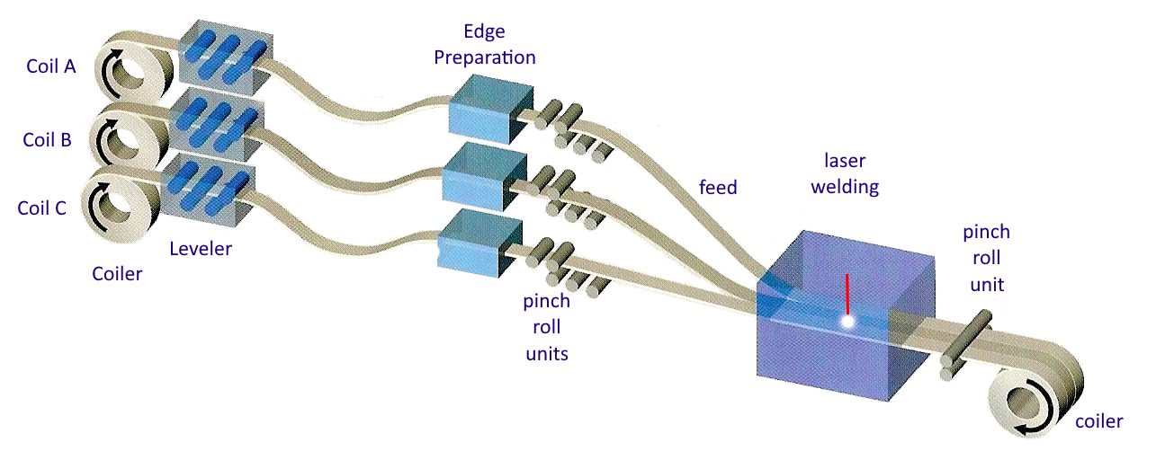
![Figure 3: General usage of Tailor Welded Coils [S-28]](https://ahssinsights.org/wp-content/uploads/2020/07/tailor-welded-cole-common-use.jpg)