Talk Like a Metallurgist

Talk Like a Metallurgist

Every industry has its own jargon. In certain settings, these words might be necessary – you wouldn’t want a cardiologist talking to a gastroenterologist about boo-boos and upset tummies. But when these professionals talk with their patients, it’s sometimes necessary for them to use much simpler words. That is, assuming the goal is to actually communicate the issues and concerns.

The steel industry is no different. We use words that have precise meanings in our daily discussions, and we forget that many people we work with don’t have exposure to the terminology that we are accustomed to using. What follows is a brief tour of the words and phrases you are likely to hear when speaking with your metallurgical representative.

Let’s start with the most common word: steel. Simply, steel is just an alloy of iron with up to about 2% carbon. Of course, other elements are in the composition. These fall into two categories: those intentionally added to improve one or more properties (called alloying elements), and those remaining from the steelmaking process that are too costly to remove relative to the benefit the removal would provide (called residual elements). High residuals are usually bad, typically because they lower ductility. But remember high is a relative term. The value may be higher than the standard to which you ordered (which is a cause for rejection), or just higher than what you’ve received in the past. If they are within the tolerance allowed within the standard, the product should still meet your strength and ductility requirements.

I’ve worked with metal formers who believe “steel is steel” and that all grades should behave the same way. According to the World Steel Association, there are more than 3,500 different grades of steel, each with unique properties and characteristics, 75% of which were developed in the past 20 years. Certainly, not all of these are sheet steels, but even within this category, there are sizable numbers. When it comes to just advanced high-strength sheet steels, more than 60 unique grades are available today.

The most common sheet steel grade is routinely called mild steel. Mild steels are low-carbon steels with no alloying elements added for substantial strengthening, and for that reason, they are characterized by relatively lower yield strength. However, there is no single grade or chemistry that meets this definition. Grade definitions require the steelmaker to meet certain chemistry or property limits. These grades are ordered to a standard usually written by the steel producer, a pertinent industry society (like ASTM, Euronorm, or JFS), or the end-user OEM. What is generally thought of as mild steel has chemistry, strength, and ductility overlapping many defined grades. Steel users should order to standards that define and constrain important properties like strength and ductility.

If you hang out with enough metallurgists, you are bound to hear passionate discussions about the iron-carbon phase diagram. (Why you are hanging around metallurgists is another topic entirely.) Before explaining the purpose of a phase diagram, it’s important to understand that a phase is a region of a material that is physically distinct, chemically uniform, and can be seen as different from the rest of the material. Ice and water are two phases that exist in my beverage. You’ll find a chocolate chip phase in my vanilla ice cream. And you’ll find ferrite in my steel – tasty! The properties of each of these change if you increase temperature (converting H2O from a solid to a liquid and eventually a gas) or if you add more alloying elements (chocolate chips or carbon). If you add a lot of that alloying element, you can get something entirely different like ripple or pearlite.

A phase diagram is a graphical representation of composition on the horizontal axis and temperature on the vertical axis. Two important phase diagrams are shown below. The far-left side of each represents 100% vanilla or 100% iron. Different phases exist as the temperature increases, or as the product is alloyed with increasing amounts of either chocolate or carbon.


Vanilla Chocolate Phase Diagram

Figure 1: Vanilla-Chocolate Phase Diagram A-77


Iron Carbon Phase Diagram

     Figure 2: Iron Carbon Phase DiagramA-78


Atoms arrange themselves in three-dimensional patterns called lattices. Think about billiard balls in multiple layers. The balls can be one layer directly above the prior one, or they can be shifted and rest in the crevice formed by adjacent balls in the layer below. The balls are all the same material, but the gap size changes with different arrangements. This is what happens with steel. At lower temperatures, only up to 0.02% carbon fits in the gap. This orientation is called ferrite. At higher temperatures, a different atomic orientation is stable, which we call austenite. Up to 2% carbon can fit into this arrangement of atoms. For low-carbon steels under normal conditions, austenite cannot exist at room temperature – when the steel is slowly cooled, it changes from austenite to a combination of ferrite and a mixture of phases called pearlite. However, heating a certain chemistry to the austenitic zone followed by rapidly cooling just right bypasses the natural conversion to ferrite and pearlite, and creates a structure that contains austenite at room temperature. This leads to the term retained austenite, which is the phase that gives TRIP and 3rd Generation Steels excellent ductility. More on these later.

100% iron is very soft. As a matter of fact, 100% of any element is very soft. As an example, think about gold. 24-carat gold is pure gold. You might think that a wedding ring, as a symbol of long-lasting love and devotion, should be made from 100% gold. In reality, many gold bands are made from 12-carat gold, which is half gold and half impurities. (Showing your love by giving something 50% impure perhaps is not the best marketing approach.) Adding alloying elements to gold is done to improve certain characteristics, like strength, making the alloy appropriate for the applications it serves.

When we talk about ferrite at room temperature, that’s iron with no more than 80 parts per million carbon. That’s really close to pure iron, so when we hear the term ferrite, we should think of something that is really soft, low-strength, and very ductile.

If additional strength is needed, then more alloying elements must be used in addition to carbon. The next most cost-effective alloying element is manganese which produces higher-strength steels called carbon-manganese steels. These are substitutional solid solutions strengthened, where the atoms of manganese swap into where atoms of iron would otherwise go. These grades have limited ductility, especially at higher carbon and manganese contents, so they are used in structural applications that do not need a lot of formability and are therefore also called structural steels (SS). In the ASTM standard specification covering many sheet steels, ASTM A1008/A1008M, these grades are grouped in the SS category.

Around 1980, steelmakers rolled out a new approach to getting higher strength levels while minimizing the loss of elongation usually seen with higher strengths. They do this by strengthening the ferrite through the addition of very small quantities of titanium, niobium, and vanadium to form carbide and nitride precipitates. These microalloying additions are used in precipitation hardening of the ferrite to create High Strength Low Alloy (HSLA) steels.

Switching gears a bit to discuss something unrelated to sheet steel but a process with which we might be familiar: forged gears. We want forged gears to be hard and high strength. Typical production of gears involves heating up a steel alloy of certain chemistry, followed by rapid cooling (quenching) them faster than a critical cooling rate. The structure that’s produced is called martensite. If the quench rate is only a little too slow, a different phase called bainite can be produced. While martensite is the highest strength phase, it has limited elongation. Bainite is a little lower in strength but has higher elongation and toughness compared with martensite. Bainite shines in applications needing cut-edge ductility during stretch flanging.

Martensite wasn’t commonly found as a microstructural component during most of the history of automotive sheet steels due to the limited number of companies having an annealing line with appropriate quenching capabilities. This started to change around the turn of the millennium when newer annealing lines were installed with the ability to hold at a specific temperature which may be lower than the annealing temperature followed by quenching to another much lower temperature. This led to greater production of the first generation of Advanced High-Strength Steels (AHSS), including grades that have a microstructure of only martensite

Dual Phase steels are the most common AHSS. As you might guess, there are two phases in Dual-Phase steels. Ferrite and martensite are the two phases: ferrite is super-soft and comprises the majority of the microstructure, while martensite is super-hard and takes up 10% (590DP) to 40% (980DP) of the microstructure. The more martensite, the stronger the steel. Elongation is the ductility measured in a tensile test, and since most of the structure is ferrite, these steels have exceptional elongation for the strength level. However, there is a large hardness difference between ferrite and martensite, leading to crack initiation sites and resulting in poor cut-edge ductility during stretch flanging.

[A brief digression on testing. Tensile testing takes a standard sample shape, typically looking like a bone you might give a dog to chew on, and pulls it in tension from the edges. The test results include yield strength, tensile strength, and total elongation, commonly called the YTEs or TYEs based on the initials. More information comes out of the tensile test, covered elsewhere. However, the tensile test is usually not used to measure cut-edge ductility. Cut edge ductility is typically characterized by the hole expansion test, where a punched hole is expanded with a conical punch until a through-thickness crack forms.]

Ferrite-bainite steels have a combination of decent elongation (from the ferrite) and excellent cut-edge ductility (from the bainite). Yes, your assumption is correct that there are only two phases in these steels, with ferrite being about 85% of the microstructure. Due to the way these are produced, ferrite-bainite steels are available as hot-rolled products only. That’s in contrast with Complex Phase (CP) steels, which can be found either at hot-rolled or cold-rolled thicknesses.

Soft ferrite is the primary microstructural component in DP steels and the soon-to-be-discussed TRIP steels, which results in low yield strength and relatively high elongation. On the other hand, the primary microstructural components of complex phase steels are bainite and precipitation-strengthened ferrite, with martensite and retained austenite also present in lower amounts. Lacking soft ferrite, these steels have relatively high yield strength and low elongation as measured in a tensile test, but the bainite leads to exceptional cut-edge ductility as measured in a hole expansion test. Multi-phase steels are a related product. Some OEMs group CP and MP steels in the same category, while others say that CP steels are engineered to favor improved bendability and cut edge extension over tensile elongation at the same tensile strength and that MP steels target balancing the fracture resistance needed for better bendability and hole expansion with the necking resistance found with higher uniform elongation and n-value.

TRIP steels contain mostly ferrite surrounding islands of martensite, as well as some bainite and retained austenite. The amount of bainite is pretty low, so it doesn’t add much to the cut-edge ductility. But the magic is in the retained austenite. Austenite is a very ductile phase. What makes this a special phase is that as austenite-containing steels deform, the atoms rearrange and the austenite transforms into martensite, giving the steel enhanced ductility. (Jargon alert: Another word for ductility used by professionals is plasticity.) A quick review: this enhanced ductility comes from austenite transforming to martensite. In other words, these steels have Transformation Induced Plasticity (TRIP).

Wouldn’t it be great to have an alloy that was just austenite? We’d have a high-strength, high-ductility product. There are two types of steels that are in this category. First are austenitic stainless steels in the 3XX family, like SS304 and SS316. In these alloys, austenite is stable at room temperature, but these require approximately 18% chromium and 8% nickel. Next are TWIP steels. These may look like TRIP steels from how they are written, but these steels get their plasticity differently. TWIP steels deform by a mechanism known as twinning, so they are described as Twinning Induced Plasticity Steels (TWIP). Of course, there are no free lunches. To get fantastic formability properties, a lot of alloying is necessary. This drives up the steelmaking complexity and cost. The alloying elements also make welding much more challenging. TWIP steels are called second-generation advanced high-strength steels.

The 3rd Generation Advanced High-Strength Steels (3rd Gen AHSS or 3rd Gen) are made possible by another advance in annealing technology, allowing steelmakers to produce a refined microstructure. Nearly all 3rd Gen steels have retained austenite in the microstructure and therefore benefit from a high strength, high ductility combination. The latest annealing lines used to make these steels come equipped to not just hold and quench to defined temperatures but have reheating capability followed by another hold and quench to different temperature targets. This allows for the creation of an engineered balance and distribution of ferrite, bainite, martensite, and austenite in the microstructure.

The resultant tensile property ranges from 3rd Gen steels produced at different companies may be similar, but their methods of getting those properties are a function of chemistry and the capabilities and characteristics of the equipment used to produce them. A different chemistry approach may result in different weldability, for example, so users are encouraged to perform thorough due diligence before switching suppliers. The days of steel being simply a commodity are in the past as it relates to these highly engineered higher strength steels.


Final thought 1: What’s an MPa?

This note may have a global readership, but this answer is focused on the countries that haven’t embraced the metric system. Megapascals, abbreviated MPa, is a measure of strength, just like pounds per square inch (psi) or force per area. Like Celsius and Fahrenheit or inches and millimeters, we can convert between them easily enough. There are 1000 psi in a ksi, with k being the abbreviation for kilopounds. And there are 6.895 ksi in an MPa. Make your life easier and focus on a 7:1 difference. 100 ksi is about 700 MPa.


Final thought 2: What about Press Hardening Steels?

Press hardening steel for hot stamping is a separate topic with a lot of nuances. One of the biggest differences is how the properties develop. For cold stamping operations, the stamping company is responsible for creating the formed part from sheet metal supplied to the necessary strength. With press hardening steels, the stamping company creates both the shape and the strength. Different grades come from a combination of different chemistries from the steelmaker and different heating and cooling profiles at the stamping location. The chosen corrosion protection approach impacts the various options. Learn more at the Press Hardening Primer on this site.


Final thought 3: Don’t hesitate to ask questions.

If your metallurgical representative says something that you don’t understand, ask for clarification. Your suppliers want to be your valued partner for more than just a simple transaction. Quite likely, your met rep is passionate about their offerings and would love to talk about them. If you get a deeper understanding of what makes one product different from another, then you’ll be in a better position to weigh the benefits against the inevitable constraints, leading to an optimized material selection. Remember, communication is the key to success for all parties.


Thanks go to author Daniel J. Schaeffler, Ph.D., President, Engineering Quality Solutions, Inc.

Danny Schaeffler is the Metallurgy and Forming Technical Editor of the AHSS Applications Guidelines available from WorldAutoSteel.  He is founder and President of Engineering Quality Solutions (EQS).  Danny writes the monthly “Metal Matters” column for Metalforming Magazine, and provides seminars on sheet metal formability for the Precision Metalforming Association.  He has written for Stamping Journal and The Fabricator, and has lectured at FabTech.  Danny is passionate about training new and experienced employees at manufacturing companies about how sheet metal properties impact their forming success.


Roll Forming

Roll Forming

Roll Forming
Case Study: How Steel Properties Influence the Roll Forming Process
Coil Shape Imperfections Influencing Roll Forming
Roll Stamping


Roll Forming

Roll Forming takes a flat sheet or strip and feeds it longitudinally through a mill containing several successive paired roller dies, each of which incrementally bends the strip into the desired final shape. The incremental approach can minimize strain localization and compensate for springback. Therefore, roll forming is well suited for generating many complex shapes from Advanced High-Strength Steels, especially from those grades with low total elongation, such as martensitic steel. The following video, kindly provided by Shape Corp.S-104, highlights the process that can produce either open or closed (tubular) sections.

The number of pairs of rolls depends on the sheet metal grade, finished part complexity, and the design of the roll-forming mill. A roll-forming mill used for bumpers may have as many as 30 pairs of roller dies mounted on individually driven horizontal shafts.A-32

Roll forming is one of the few sheet metal forming processes requiring only one primary mode of deformation. Unlike most forming operations, which have various combinations of forming modes, the roll-forming process is nothing more than a carefully engineered series of bends. In roll forming, metal thickness does not change appreciably except for a slight thinning at the bend radii.

Roll forming is appropriate for applications requiring high-volume production of long lengths of complex sections held to tight dimensional tolerances. The continuous process involves coil feeding, roll forming, and cutting to length. Notching, slotting, punching, embossing, and curving combine with contour roll forming to produce finished parts off the exit end of the roll-forming mill. In fact, companies directly roll-form automotive door beam impact bars to the appropriate sweep and only need to weld on mounting brackets prior to shipment to the vehicle assembly line.A-32 Figure 1 shows an example of automotive applications that are ideal for the roll-forming process.
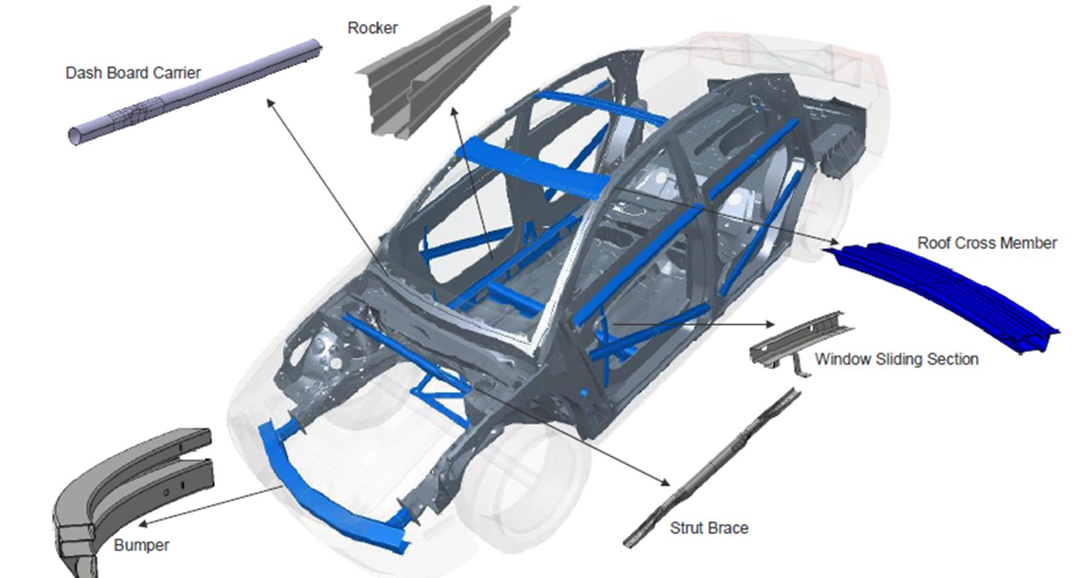
Figure 1: Body components that are ideally suited for roll-forming.

Figure 1: Body components that are ideally suited for roll-forming.


Roll forming can produce AHSS parts with:

  • Steels of all levels of mechanical properties and different microstructures.
  • Small radii depending on the thickness and mechanical properties of the steel.
  • Reduced number of forming stations compared with lower strength steel.

However, the high sheet-steel strength means that forces on the rollers and frames in the roll-forming mill are higher. A rule of thumb says that the force is proportional to the strength and thickness squared. Therefore, structural strength ratings of the roll forming equipment must be checked to avoid bending of the shafts. The value of minimum internal radius of a roll formed component depends primarily on the thickness and the tensile strength of the steel (Figure 2).
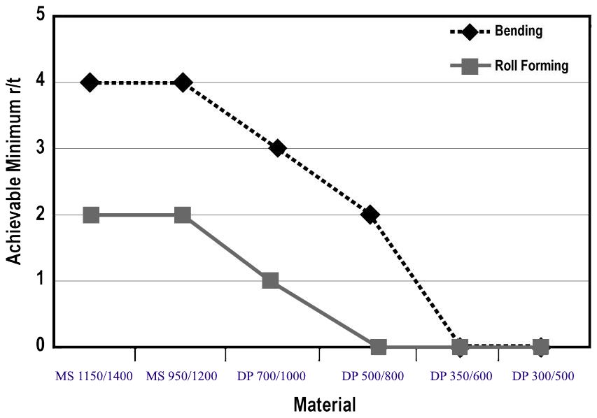
Figure 2: Achievable minimum r/t values for bending and roll forming for different strength and types of steel.S-5

Figure 2: Achievable minimum r/t values for bending and roll forming for different strength and types of steel.S-5


As seen in Figure 2, roll forming allows smaller radii than a bending process. Figure 3 compares CR1150/1400-MS formed with air-bending and roll forming. Bending requires a minimum 3T radius, but roll forming can produce 1T bends.S-30
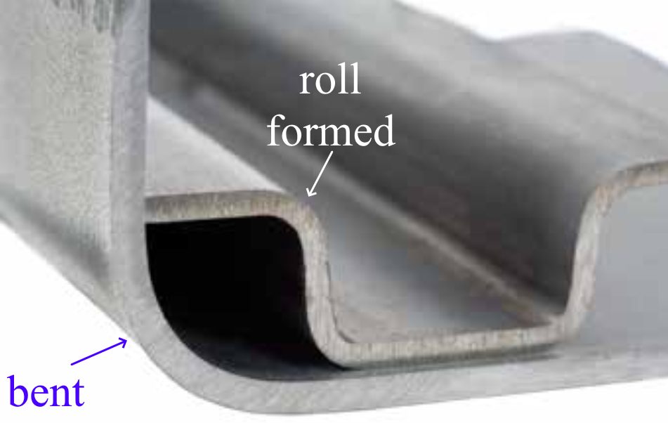
Figure 3: CR1150/1400-MS (2 mm thick) has a minimum bend radius of 3T, but can be roll formed to a 1T radius.S-30

Figure 3: CR1150/1400-MS (2 mm thick) has a minimum bend radius of 3T, but can be roll formed to a 1T radius.S-30


The main parameters having an influence on the springback are the radius of the component, the sheet thickness, and the strength of the steel. As expected, angular change increases for increased tensile strength and bend radius (Figure 4).

Figure 4: Angular change increases with increasing tensile strength and bend radii.A-4

Figure 4: Angular change increases with increasing tensile strength and bend radii.A-4


Figure 5 shows a profile made with the same tool setup for three steels at the same thickness having tensile strength ranging from 1000 MPa to 1400 MPa. Even with the large difference in strength, the springback is almost the same.

Figure 5: Roll formed profile made with the same tool setup for three different steels. Bottom to Top: CR700/1000-DP, CR950/1200-MS, CR1150/1400-MS.S-5

Figure 5: Roll formed profile made with the same tool setup for three different steels. Bottom to Top: CR700/1000-DP, CR950/1200-MS, CR1150/1400-MS.S-5

Citation A-33 provides guidelines for roll forming High-Strength Steels:

  • Select the appropriate number of roll stands for the material being formed. Remember the higher the steel strength, the greater the number of stands required on the roll former.
  • Use the minimum allowable bend radius for the material in order to minimize springback.
  • Position holes away from the bend radius to help achieve desired tolerances.
  • Establish mechanical and dimensional tolerances for successful part production.
  • Use appropriate lubrication.
  • Use a suitable maintenance schedule for the roll forming line.
  • Anticipate end flare (a form of springback). End flare is caused by stresses that build up during the roll forming process.
  • Recognize that as a part is being swept (or reformed after roll forming), the compression of metal can cause sidewall buckling, which leads to fit-up problems.
  • Do not roll form with worn tooling, as the use of worn tools increases the severity of buckling.
  • Do not expect steels of similar yield strength from different steel sources to behave similarly.
  • Do not over-specify tolerances.

Guidelines specifically for the highest strength steelsA-33:

  • Depending on the grade, the minimum bend radius should be three to four times the thickness of the steel to avoid fracture.
  • Springback magnitude can range from ten degrees for 120X steel (120 ksi or 830 MPa minimum yield strength, 860 MPa minimum tensile strength) to 30 degrees for M220HT (CR1200/1500-MS) steel, as compared to one to three degrees for mild steel. Springback should be accounted for when designing the roll forming process.
  • Due to the higher springback, it is difficult to achieve reasonable tolerances on sections with large radii (radii greater than 20 times the thickness of the steel).
  • Rolls should be designed with a constant radius and an evenly distributed overbend from pass to pass.
  • About 50 percent more passes (compared to mild steel) are required when roll forming ultra high-strength steel. The number of passes required is affected by the number of profile bends, mechanical properties of the steel, section depth-to-steel thickness ratio, tolerance requirements, pre-punched holes and notches.
  • Due to the higher number of passes and higher material strength, the horsepower requirement for forming is increased.
  • Due to the higher material strength, the forming pressure is also higher. Larger shaft diameters should be considered. Thin, slender rolls should be avoided.
  • During roll forming, avoid undue permanent elongation of portions of the cross section that will be compressed during the sweeping process.

Roll forming is applicable to shapes other than long, narrow parts. For example, an automaker roll forms their pickup truck beds allowing them to minimize thinning and improve durability (Figure 6). Reduced press forces are another factor that can influence whether a company roll forms rather than stamps truck beds.

Figure 6: Roll Forming can replace stamping in certain applications.G-9

Figure 6: Roll Forming can replace stamping in certain applications.G-9

Traditional two-dimensional roll forming uses sequential roll stands to incrementally change flat sheets into the targeted shape having a consistent profile down the length. Advanced dynamic roll forming incorporates computer-controlled roll stands with multiple degrees of freedom that allow the finished profile to vary along its length, creating a three-dimensional profile. The same set of tools create different profiles by changing the position and movements of individual roll stands. In-line 3D profiling expands the number of applications where roll forming is a viable parts production option.

One such example are the 3D roll formed tubes made from 1700 MPa martensitic steel for A-pillar / roof rail applications in the 2020 Ford Explorer and 2020 Ford Escape (Figure 7).  Using this approach instead of hydroforming created smaller profiles resulting in improved driver visibility, more interior space, and better packaging of airbags. The strength-to-weight ratio improved by more than 50 percent, which led to an overall mass reduction of 2.8 to 4.5 kg per vehicle.S-104

Figure 7: 3D Roll Formed Profiles in 2020 Ford Vehicles using 1700 MPa martensitic steel.S-104

Figure 7: 3D Roll Formed Profiles in 2020 Ford Vehicles using 1700 MPa martensitic steel.S-104


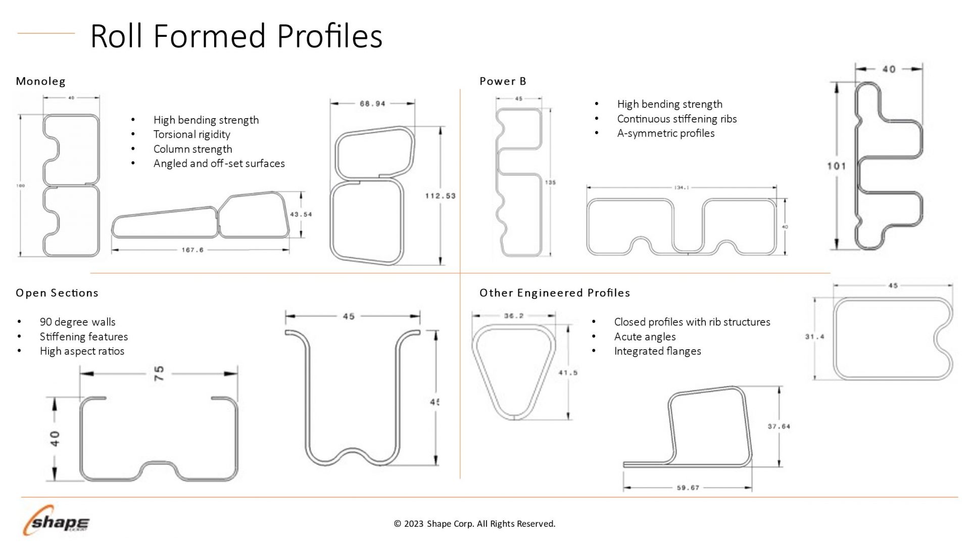
Roll forming is no longer limited to producing simple circular, oval, or rectangular profiles. Advanced cross sections such
as those shown in Figure 8 provided by Shape Corporation highlight some profile designs aiding in body structure
stiffness and packaging space reductions.
Roll Form Designs

Figure 8: Roll forming profile design possibilities. Courtesy of Shape Corporation.


In summary, roll forming can produce AHSS parts with steels of all levels of mechanical properties and different microstructures with a reduced R/T ratio versus conventional bending. All deformation occurs at a radius, so there is no sidewall curl risk and overbending works to control angular springback.


Case Study: How Steel Properties Influence the Roll Forming Process

Many thanks to Brian Oxley, Product Manager, Shape Corporation, and Dr. Daniel Schaeffler, President, Engineering Quality Solutions, Inc., for providing this case study.

Optimizing the use of roll forming requires understanding how the sheet metal behaves through the process.
Making a bend in a roll formed part occurs only when forming forces exceed the metal’s yield strength, causing plastic
deformation to occur. Higher strength sheet metals increase forming force requirements, leading to the need to have
larger shaft diameters in the roll forming mill. Each pass must have greater overbend to compensate for the increasing
springback associated with the higher strength.

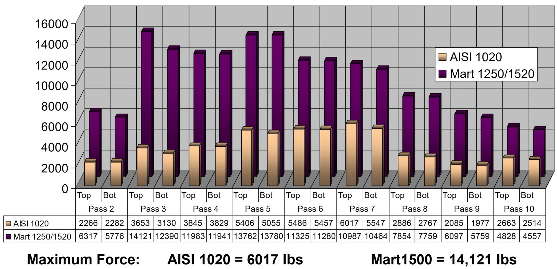
Figure 9 provides a comparison of the loads on each pass of a 10-station roll forming line when forming either AISI 1020
steel (yield strength of 350 MPa, tensile strength of 450 MPa, elongation to fracture of 15%) or CR1220Y1500T-MS, a
martensitic steel with 1220 MPa minimum yield strength and 1500 MPa minimum tensile strength.
Graph showing pass loads with maximum force levels. Gold and purple 3D bar chart

Figure 9: Loads on each pass of a roll forming line when forming either AISI 1020 steel (450 MPa tensile
strength) or a martensitic steel with 1500 MPa minimum tensile strength. Courtesy of Roll-Kraft.


Although a high-strength material requires greater forming loads, grades with higher yield strength can resist stretching
of the strip edge and prevent longitudinal deformations such as twisting or bow. Flange edge flatness after forming
either AISI 1020 or CR1220Y1500T-MS is presented in Figure 10.

Figure 10: Simulation results showing flange edge flatness of a) AISI 1020 and b) CR1220Y1500T-MS.
Assumptions for the simulation: AISI 1020 yield strength = 350 MPa; CR1220Y1500T yield strength = 1220 MPa.
Higher yield strength leads to better flatness.


Force requirements for piercing operations are a function of the sheet tensile strength. High strains in the part design
exceeding uniform elongation resulting from loads in excess of the tensile strength produces local necking, representing
a structural weak point. However, assuming the design does not produce these high strains, the tensile strength has only
an indirect influence on the roll forming characteristics.

Yield strength and flow stress are the most critical steel characteristics for roll forming dimensional control. Receiving
metal with limited yield strength variability results in consistent part dimensions and stable locations for pre-pierced
features.

Flow stress represents the strength after some amount of deformation, and is therefore directly related to the degree of
work hardening: starting at the same yield strength, a higher work hardening steel will have a higher flow stress at the
same deformation.

Two grades are shown in Figure 11: ZE 550 and CR420Y780T-DP. ZE 500, represented by the red curve, is a recovery
annealed grade made by Bilstein having a yield strength range of 550 to 625 MPa and a minimum tensile strength of 600
MPa, while CR420Y780T-DP, represented by the blue curve, is a conventional dual phase steel with a minimum yield
strength of 420 MPa and a minimum tensile strength of 780 MPa. For the samples tested, ZE 550 has a yield strength of
approximately 565 MPa, where that for CR420Y780T-DP is much lower at about 485 MPa. Due to the higher work
hardening (n-value) of the DP steel, its flow stress at 5% strain is 775 MPa, while the flow stress for the HSLA grade at 5%
strain is 620 MPa.

In conventional stamping operations, this work hardening is beneficial to delay the onset of necking. However, use of
dual-phase steels and other grades with high n-value can lead to dimensional issues in roll-formed parts. Flow stress in a
given area is a function of the local strain. Each roll station induces additional strain on the overall part, and strains vary
within the part and along the edge. This strength variation is responsible for differing springback and edge wave across
a roll-formed part.

Unlike conventional stamping, grades with a high yield/tensile ratio where the yield strength is close to the tensile
strength are better suited to produce straight parts via roll forming.
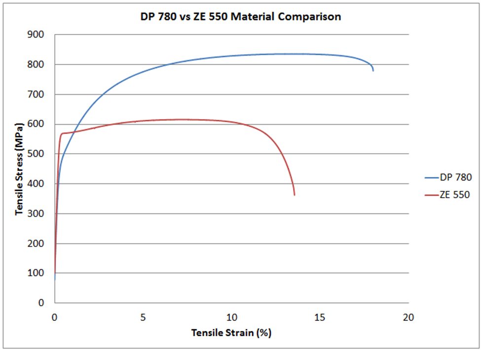
Line graph of stress/strain curves

Figure 11: Stress-strain curves for CR420Y780T-DP (blue) and ZE 550 (red). See text for description of the grades.


Total elongation to fracture is the strain at which the steel breaks during tensile testing, and is a value commonly
reported on certified metal property documents (cert sheets). As observed on the colloquially called “banana diagram”,
elongation generally decreases as the strength of the steel increases.

For lower strength steels, total elongation is a good indicator for a metal’s bendability. Bend severity is described by the
r/t ratio, or the ratio of the inner bend radius to the sheet thickness. The metal’s ability to withstand a given bend can be
approximated by the tensile test elongation, since during a bend, the outermost fibers elongate like a tensile test.

In higher strength steels where the phase balance between martensite, bainite, austenite, and ferrite play a much larger
role in developing the strength and ductility than in other steels, bendability is usually limited by microstructural
uniformity. Dual phase steels, for example, have excellent uniform elongation and resistance to necking coming from
the hardness difference between ferrite and martensite. However, this large hardness difference is also responsible for
relatively poor edge stretchability and bendability. In roll forming applications, those grades with a uniform
microstructure will typically have superior performance. As an example, refer to Figure 11. The dual phase steel shown
in blue can be bent to a 2T radius before cracking, but the recovery annealed ZE 550 grade with noticeably higher yield
strength and lower elongation can be bent to a ½T radius.

Remember that each roll forming station only incrementally deforms the sheet, with subsequent stations working on a
different region. Roll formed parts do not need to use grades associated with high total elongation, especially since
these typically have a bigger gap between yield and tensile strength.


Coil Shape Imperfections Influencing Roll Forming

Along with the mechanical properties of steel, physical shape attributes of the sheet or coil can influence the roll
forming process. These include center buckle, coil set, cross bow, and camber. Receiving coils with these imperfections
may result in substandard roll formed parts.

Flatness is paramount when it comes to getting good shape on roll formed parts. Individual OEMs or processors may
have company-specific procedures and requirements, while organizations like ASTM offer similar information in the
public domain. ASTM A1030/A1030M is one standard covering the practices for measuring flatness, and specification
ASTM A568/A568M shows methods for characterizing longitudinal waves, buckles, and camber. 

Center buckle (Figure 12), also known as full center, is the term to describe pockets or waves in the center or quarter
line of the strip. The height of pocket varies from 1/6” to 3/4”. Center buckle occurs when the central width portion of
the master coil is longer than the edges. This over-rolling of the center portion might occur when there is excessive
crown in the work roll, build-up from the hot strip mill, a mismatched set of work rolls, improper use of the benders, or
improper rolling procedures. A related issue is edge buckle presenting as wavy edges, originating when the coil edges
are longer than the central width position.
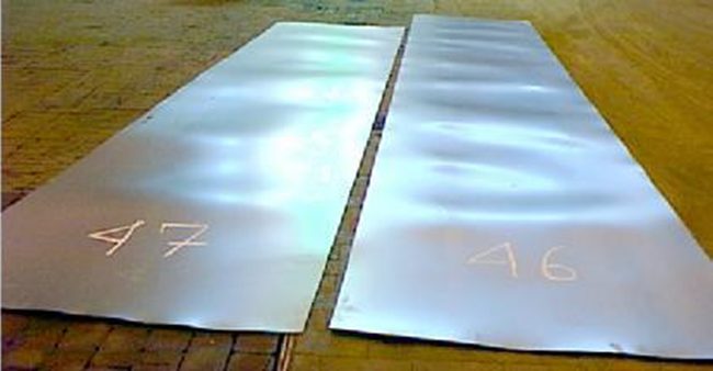
Center Buckle

Figure 12: Coil shape imperfection: Center Buckle


Coil set (Figure 13a), also known as longitudinal bow, occurs when the top surface of the strip is stretched more than the
bottom surface, causing a bow condition parallel with the rolling direction. Here, the strip exhibits a tendency to curl
rather than laying flat. To some extent, coil set is normal, and easy to address with a leveler. Severe coil set may be
induced by an imbalance in the stresses induced during rolling by the thickness reduction work rolls. Potential causes include different diameters or surface speeds of the two work rolls, or different frictional conditions along the two arcs
of contact.

Crossbow (Figure 13b) is a bow condition perpendicular to the rolling direction, and arcs downward from the high point
in the center position across the width of the sheet. Crossbow may occur if improper coil set correction practices are
employed.

Figure 13: Coil shape imperfections: A) Coil set and B) Crossbow

Figure 13: Coil shape imperfections: A) Coil set and B) Crossbow A-30


Camber (Figure 14) is the deviation of a side edge from a straight edge, and results when one edge of the steel is
elongated more than the other during the rolling process due to a difference in roll diameter or speed. The maximum
allowable camber under certain conditions is contained within specification ASTM A568/A568M, among others.

Figure 14 - Camber

Figure 14: Coil shape imperfection: Camber


Coil shape imperfections produce residual stresses in the starting material. These residual stresses combined with the
stresses from forming lead to longitudinal deviations from targeted dimensions after roll forming. Some of the resultant
shapes of roll formed components made from coils having these issues are shown in Figure 15. Leveling the coil prior to
roll forming may address some of these shape concerns, and has the benefit of increasing the yield strength, making a
more uniform product.

Figure 15

Figure 15: Shape deviations in roll formed components initiating from incoming coil shape issues:
a) camber  b) longitudinal bow  c) twist  d) flare  e) center wave (center buckle)  f) edge wave. H-66


Roll Stamping

Traditional roll forming creates products with essentially uniform cross sections.  A newer technique called Roll Stamping enhances the ability to create shapes and features which are not in the rolling axis.

Using a patented processA-48, R-9, forming rolls with the part shape along the circumferential direction creates the desired form, as shown in Figure 16.
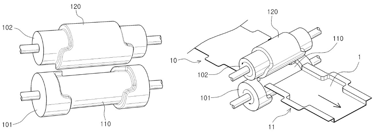
Figure 7: Roll Stamping creates additional shapes and features beyond capabilities of traditional roll forming. (Reference 1)

Figure 16: Roll Stamping creates additional shapes and features beyond capabilities of traditional roll forming. A-48


This approach can be applied to a conventional roll forming line.  In the example of an automotive door impact beam, the W-shaped profile in the central section and the flat section which attaches to the door inner panel are formed at the same time, without the need for brackets or internal spot welds (Figure 17). Sharp corner curvatures are possible due to the incremental bending deformation inherent in the process.

Figure 8: A roll stamped door beam formed on a conventional roll forming line eliminates the need for welding brackets at the edges. (Reference 2)

Figure 17: A roll stamped door part formed on a conventional roll forming line eliminates the need for welding brackets at the edges.R-9


A global automaker used this method to replace a three-piece door impact beam made with a 2.0 mm PHS-CR1500T-MB press hardened steel tube requiring 2 end brackets formed from 1.4 mm CR-500Y780T-DP to attach it to the door frame, shown in Figure 18. The new approach, with a one-piece roll stamped 1.0 mm CR900Y1180T-CP complex phase steel impact beam, resulted in a 10% weight savings and 20% cost savings.K-58 This technique started in mass production on a Korean sedan in 2017, a Korean SUV in 2020, and a European SUV in 2021.K-58
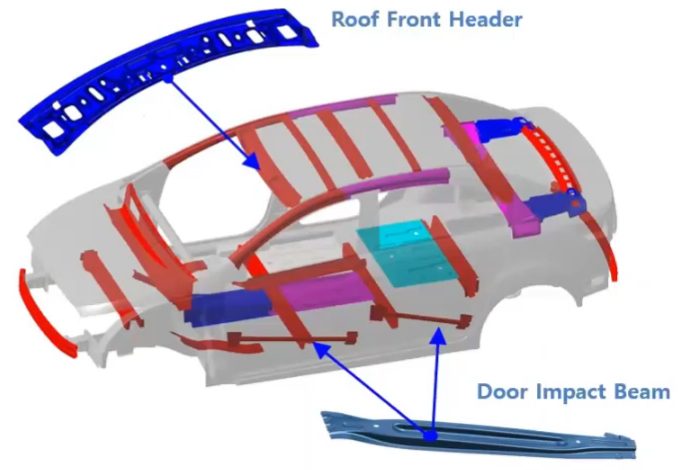
Figure 10: Some Roll Stamping Automotive Applications (Citation D)

Figure 18: Some Roll Stamping Automotive Applications.K-58


Photo of Brian OxleyThanks are given to Brian Oxley, Product Manager, Shape Corporation, for his contributions to the Roll Forming Case Study and Coil Shape Imperfections section. Brian Oxley is a Product Manager in the Core Engineering team at Shape Corp. Shape Corp. is a global, full-service supplier of lightweight steel, aluminum, plastic, composite and hybrid engineered solutions for the automotive industry. Brian leads a team responsible for developing next generation products and materials in the upper body and closures space that complement Shape’s core competency in roll forming. Brian has a Bachelor of Science degree in Material Science and Engineering from Michigan State University.

A New Global Formability Diagram

A New Global Formability Diagram

Bubble chart. Banana diagram. Steel strength ductility diagram—it’s been called a lot of things over the years. But the 2021 chart shown in Figure 1 is the subject of hundreds of requests for use we receive from engineers and students all over the world and appears in thousands of presentations and papers. Because of that, we periodically update it to make sure it reflects the most current picture of both commercially available, as well as emerging steel grades. In this blog, we are providing our updated GFD for download as well as definitions of steel classifications, as agreed to by our member companies.

Figure 2: The Global Formability Diagram comparing strength and elongation of current and emerging steel grades.

Figure 1: The 2021 Global Formability Diagram comparing strength and elongation of current and emerging steel grades.


Steel Classifications

There are different ways to classify automotive steels. One is a metallurgical designation providing some process information. Common designations include lower-strength steels (interstitial-free and mild steels); conventional high strength steels, such as bake hardenable and high-strength, low-alloy steels (HSLA); and Advanced High-Strength Steels (AHSS) such as dual phase and transformation-induced plasticity steels. Additional higher strength steels include press hardening steels and steels designed for unique applications that have improved edge stretch and stretch bending characteristics.

A second classification method important to part designers is strength of the steel. This document will use the general terms HSLA and AHSS to designate all higher strength steels. The principal difference between conventional HSLA steels and AHSS is their microstructure. Conventional HSLA steels are single-phase ferritic steels with a potential for some pearlite in C-Mn steels.

AHSS are primarily steels with a multiphase microstructure containing one or more phases other than ferrite, pearlite, or cementite – for example martensite, bainite, austenite, and/or retained austenite in quantities sufficient to produce unique mechanical properties. Some types of AHSS have a higher strain hardening capacity resulting in a strength-ductility balance superior to conventional steels. Other types have ultra-high yield and tensile strengths and show a bake hardening behavior.

What are 3rd Gen Steels?

Third Generation, or 3rd Gen, AHSS builds on the previously developed 1st Gen AHSS (DP, TRIP, CP, MS, and PHS) and 2nd Gen AHSS (TWIP), with global commercialization starting around 2020. Third Gen AHSS are multi-phase steels engineered to develop enhanced formability as measured in tensile, sheared edge, and/or bending tests. Typically, these steels rely on retained austenite in a bainite or martensite matrix and potentially some amount of ferrite and/or precipitates, all in specific proportions and distributions, to develop these enhanced properties.

Graphical Presentation

Generally, elongation (a measure of ductility) decreases as strength increases. Plotting elongation on the vertical axis and strength on the horizontal axis leads to a graph starting in the upper left (high elongation, lower strength) and progressing to the lower right (lower elongation, higher strength). When considering conventional steels and the first generation of advanced high strength steels, this shape led to the colloquial description of calling this the banana diagram.

With the continued development of advanced steel options, it is no longer appropriate to describe the plethora of options as being in the shape of a banana. Instead, with new grades filling the upper right portion of Figure 1, perhaps it is more accurate to describe this as the football diagram as the options now start to fall into the shape of an American or Rugby Football. Officially, it is known as the steel Global Formability Diagram.

Even this approach has its limitations. Elongation is only one measure of ductility. Other ductility parameters are increasingly important with AHSS grades, such as hole expansion and bendability. There are several other approaches that have been proposed by experts around the world. Have a look at our Defining Steels article, from which this article was drawn, to learn more about them. You will also find within Defining Steels a detailed explanation of the nomenclature used throughout the Guidelines to define steels. If you have questions, please use the Comments tool below or on the Defining Steels page.

Download the GFD

Because of its popularity, we provide high resolution image files of the GFD here for your download and use. Please source it “Courtesy of WorldAutoSteel” in your papers and presentations. We are happy for you to use it.  If you require our signed permission, please write us at steel@worldautosteel.org. We’ll respond quickly.

* The Guidelines use the general terms HSLA and AHSS to designate all higher strength steels.

Talk Like a Metallurgist

Defining Steels


Basis

There are different ways to classify automotive steels. One is a metallurgical designation providing some process information. Common designations include lower-strength steels (interstitial-free and mild steels); conventional high strength steels, such as bake hardenable and high-strength, low-alloy steels (HSLA); and Advanced High-Strength Steels (AHSS) such as dual phase and transformation-induced plasticity steels. Additional higher strength steels include press hardening steels and steels designed for unique applications that have improved edge stretch and stretch bending characteristics.

A second classification method important to part designers is strength of the steel. This document will use the general terms HSLA and AHSS to designate all higher strength steels. The principal difference between conventional HSLA steels and AHSS is their microstructure. Conventional HSLA steels are single-phase ferritic steels with a potential for some pearlite in C-Mn steels. AHSS are primarily steels with a multiphase microstructure containing one or more phases other than ferrite, pearlite, or cementite – for example martensite, bainite, austenite, and/or retained austenite in quantities sufficient to produce unique mechanical properties. Some types of AHSS have a higher strain hardening capacity resulting in a strength-ductility balance superior to conventional steels. Other types have ultra-high yield and tensile strengths and show a bake hardening behavior.

AHSS include all martensitic and multiphase steels having a minimum specified tensile strength of at least 440 MPa. Those steels with very high minimum specified tensile strength are sometimes referred to as Ultra High Strength Steels (UHSS). Several companies choose 980 MPa as the threshold where “Ultra” high strength begins, while others use higher thresholds of 1180 MPa or 1270 MPa. There is no generally accepted definition among the producers or users of the product. The difference between AHSS and UHSS is in terminology only – they are not separate products. The actions taken by the manufacturing community to form, join, or process is ultimately a function of the steel grade, thickness, and mechanical properties. Whether these steels are called “Advanced” or “Ultra” does not impact the technical response.

Third Generation, or 3rd Gen, AHSS builds on the previously developed 1st Gen AHSS (DP, TRIP, CP, MS, and PHS) and 2nd Gen AHSS (TWIP), with global commercialization starting around 2020. 3rd Gen AHSS are multi-phase steels engineered to develop enhanced formability as measured in tensile, sheared edge, and/or bending tests. Typically, these steels rely on retained austenite in a bainite or martensite matrix and potentially some amount of ferrite and/or precipitates, all in specific proportions and distributions, to develop these enhanced properties.

Nomenclature

Historically, HSLA steels were described by their minimum yield strength. Depending on the region, the units may have been ksi or MPa, meaning that HSLA 50 and HSLA 340 both describe a High Strength Low Alloy steel with a minimum yield strength of 50 ksi = 50,000 psi ≈ 340 MPa. Although not possible to tell from this syntax, many of the specifications stated that the minimum tensile strength was 70 MPa to 80 MPa greater than the minimum yield strength.

Development of the initial AHSS grades evolved such that they were described by their metallurgical approach and minimum tensile strength, such as using DP590 to describe a dual phase steel with 590 MPa tensile strength. Furthermore, when Advanced High Strength Steels were first commercialized, there was often only one option for a given metallurgical type and tensile strength level. Now, for example, there are multiple distinct dual phase grades with a minimum 980 MPa tensile strength, each with different yield strength or formability.

To highlight these different characteristics throughout this website, each steel grade is identified by whether it is hot rolled or cold rolled, minimum yield strength (in MPa), minimum tensile strength (in MPa), and metallurgical type. Table 1 lists different types of steels.

Table 1: Different Types of Steels and Associated Abbreviations.

Table 1: Different Types of Steels and Associated Abbreviations.


As an example, CR-500Y780T-DP describes a cold rolled dual phase steel with 500 MPa minimum yield strength and 780 MPa minimum ultimate tensile strength. There is also another grade with the same minimum UTS, but lower yield strength: CR440Y780T-DP. If the syntax is simply DP780, the reader should assume either that the referenced study did not distinguish between the variants or that the issues described in that section applies to all variants of a dual phase steel with a minimum 780 MPa tensile strength.

Another syntax issue is the presentation of the strength (yield or tensile), and whether it is rounded to the nearest 10 or 50 MPa. For example, consider DP980 compared with DP1000. Both forms represent essentially the same grade. In Europe, this steel may be described as having a tensile strength of 100 kgf/mm2, corresponding to 981 N/mm2 (981 MPa), and expressed as DP980. In Asia, the steel may be referred to as 100K (an abbreviation for 100 kgf/mm2). In other parts of the world, it may be rounded to nearest 50 MPa, as DP 1000. This naming approach applies to many grades, with some shown in Table 2. In some cases, although the OEM specification may list the steel as DP800 (for example), the minimum tensile strength requirement may still be 780 MPa. Furthermore, independent of the chosen naming syntax, the steel company will supply to the actual specification requirements, and will use different process controls to meet a 780 MPa minimum compared with an 800 MPa minimum.

Table 1: Syntax Related to AHSS Strength Levels

Table 2: Syntax Related to AHSS Strength Levels


Press hardening steels sometimes require a different syntax. Some OEMs will use a similar terminology as described above. For example: CR-950Y1300T-PH (PH stands for Press Hardenable or Press Hardened) or CR-950Y1300T-MB (MB stands for Manganese-Boron steel) can describe the same cold rolled press hardening steel with 950 MPa minimum yield strength and 1300 MPa minimum tensile strength after completing the press hardening operation. Other specifications may show suffixes which highlight the forming process used, such as -DS for direct hot stamping, -IS for indirect hot stamping and MS for a multi-step process. Furthermore, sources may describe this product focused on its typical tensile strength as PHS1500T. The abbreviation PQS (Press Quenched Steel) is typically used for grades that do not harden after hot stamping. These may be noted as PQS450 and PQS550, where the numbers stand for the approximate minimum tensile strength after the hot stamping cycle (see the section on Grades With Higher Ductility on the linked page).

Graphical Presentation

Generally, elongation (a measure of ductility) decreases as strength increases. Plotting elongation on the vertical axis and strength on the horizontal axis leads to a graph starting in the upper left (high elongation, lower strength) and progressing to the lower right (lower elongation, higher strength). This shape led to the colloquial description of calling this the banana diagram.

Figure 1: A generic banana diagram comparing strength and elongation.

Figure 1: A generic “banana” diagram comparing strength and elongation.


With the continued development of advanced steel options, it is no longer appropriate to describe the plethora of options as being in the shape of a banana. Instead, with new grades filling the upper right portion (see Figure 2), perhaps it is more accurate to describe this as the football diagram as the options now start to fall into the shape of an American or Rugby Football.  Officially, it is known as the steel Global Formability Diagram.

Figure 2: The Global Formability Diagram comparing strength and elongation of current and emerging steel grades.

Figure 2: The Global Formability Diagram comparing strength and elongation of current and emerging steel grades.  Click here for a high resolution download. Source: Courtesy of WorldAutoSteel


Even this approach has its limitations. Elongation is only one measure of ductility. Other ductility parameters are increasingly important with AHSS grades, such as hole expansion and bendability. BillurB-61 proposed a diagram comparing the bend angle determined from the VDA238-100 testV-4 with the yield strength for various press hardened and press quenched steels.

Figure 3: VDA Bending Angle typically decreases with increasing yield strength of PHS/PQS grades.B-61

Figure 3: VDA Bending Angle typically decreases with increasing yield strength of PHS/PQS grades.B-61


Figure 4 shows a local/global formability map sometimes referred to as the Hance Diagram named after the researcher who proposed it.H-16  This diagram combines measures of local formability (characterized by true fracture strain) and global formability (characterized by uniform elongation), providing insight on different characteristics associated with many steel grades and helping with application-specific material grade selection. For example, if good trim conditions still create edge splits, selecting materials higher on the vertical axis may help address the edge-cracking problems. Likewise, global formability necking or splitting issues can be solved by using grades further to the right on the horizontal axis.

Figure 4: The Local/Global Formability Map combines measures of local formability (true fracture strain) and global formability (uniform elongation) to highlight the relative characteristics of different grades. In this version from Citation D-12, the colors distinguish different options at each tensile strength level.

Figure 4: The Local/Global Formability Map combines measures of local formability (true fracture strain) and global formability (uniform elongation) to highlight the relative characteristics of different grades. In this version from Citation D-12, the colors distinguish different options at each tensile strength level.


Grade Portfolio

Previous AHSS Application Guidelines showcased a materials portfolio driven by the FutureSteelVehicle (FSV) program, with more than twenty new grades of AHSS acknowledged as commercially available by 2020. The AHSS materials portfolio continues to grow, as the steel industry responds to requirements for high strength, lightweight steels. Table 3 reflects available AHSS grades as well as grades under development and nearing commercial application.  The Steel Grades page provides details about these grades and their applications.

Table 3:  Commercially available AHSS Grades and grades under development for near-term application.  Grade names shown in Italicized Bold were available in FutureSteelVehicle. For all but PQS/PHS, Grade Name indicates the minimum yield strength, minimum tensile strength, and the type of AHSS. The min EL column indicates a typical minimum total elongation value, which may vary based on test sample shape, gauge length, and thickness. PQS/PHS grade name indicates nominal tensile strength.

Table 3:  Commercially available AHSS Grades and grades under development for near-term application.  Grade names shown in Italicized Bold were available in FutureSteelVehicle. For all but PQS/PHS, Grade Name indicates the minimum yield strength, minimum tensile strength, and the type of AHSS. The min EL column indicates a typical minimum total elongation value, which may vary based on test sample shape, gauge length, and thickness. PQS/PHS grade name indicates nominal tensile strength.


Global automakers create steel specification criteria suited for their vehicle targets, manufacturing infrastructure, and other constraints. Although similar specifications exist at other companies, perfect overlap of all specifications is unlikely.  Global steelmakers have different equipment, production capabilities, and commercial availability.

Minimum or typical mechanical properties shown on this web page and throughout this site illustrates the broad range of AHSS grades that may be available. Properties of hot rolled steels can differ from cold rolled steels. Coating processes like hot dip galvanizing or galvannealing subjects the base metal to different thermal cycles that affect final properties. Test procedures and requirements have a regional or OEM influence, such as preference to using tensile test gauge length of 50 mm or 80 mm, or specifying minimum property values parallel or perpendicular to the rolling direction.

Steel users must communicate directly with individual steel companies to determine specific grade availability and the specific associated parameters and properties, such as:

  • Chemical composition specifications,
  • Mechanical properties and ranges,
  • Thickness and width capabilities,
  • Hot-rolled, cold-rolled, and coating availability,
  • Joining characteristics.


Talk Like a Metallurgist

PHS Tailored Products


Introduction

Some automotive components may require higher stiffness, strength, or energy absorbing capacity in a confined local area. One method to achieve these characteristics is to spot weld separate reinforcement panels to the main component. A strategy for improving energy absorption in high-strength components involves joining a second part made from a more ductile but lower strength material.  Neither of these approaches are ideal in terms of manufacturing efficiency and product/process optimization.

Tailored parts are the term given to those parts that may have zones with different thickness, chemistry, or heat treatment, resulting in a reduced number of components, weight reduction, and/or lower costs.  These goals are achieved through part consolidation and by reducing or in some cases even eliminating joining operations.

In cold stamping operations, tailored parts (tailored products) are typically produced at the incoming coil or blank level, but are typically called “tailored blanks” or the specific process/product produced:

  • Laser Welded Tailored Blanks (LWTB, also known as Tailor Welded Blanks, or TWB) or Tailor Welded Coils (TWC – not common in press hardening),
  • Tailor Rolled Blanks (TRB) or Tailor Rolled Coils (TRC),
  • Tailor Welded Tubes (TWT) or Tailor Rolled Tubes (TRT), or
  • Patchwork Blanks,

In press hardened components, a single component may be press hardened such that it has what are known as soft zones, or areas of lower hardness possessing increased ductility. The tailored processing of these multi-strength parts can be achieved byB-14:

  • Controlling the incoming blank temperature, (Tailored Heating, pre-process)
  • Controlling the quenching rate, (Tailored Quenching, during process)
  • Partially tempering (Tailored Tempering, post-process).

These are typically called tailored parts or tailor processed parts. Lastly it is also possible to combine two techniques, that is, making a tailored part using a tailored blank.


Laser Welded Tailored Blanks (Tailor Welded Blanks)

Laser Welded Tailored Blanks (LWTB) are blanks that are produced by laser butt welding of two or more sub-blanks, as shown in Figure 1. In the industry, the terms Tailor Welded Blanks (TWB) and Laser Welded Blanks (LWB) are also used interchangably.M-46

Figure 1: Steps of making a press hardened laser welded tailored blank (re-created after Citations B-14 and A-8).

Figure 1: Steps of making a press hardened laser welded tailored blank (re-created after Citations B-14 and A-8).


Laser welded tailored blanks consist of sub-blanks with:

  • Different thicknesses, allowing for use of thinner sheet steels in areas of the component having less rigorous loading requirements. Using thinner sheets saves weight.
  • Different grades, optimizing the energy absorption and intrusion resistance characteristics in each area of the same part (such as an automotive B-pillar, see Figure 6b).
  • A combination of both.

Laser welded tailored blanks with the same thickness and grade are used to create blanks having dimensions larger than mill rolling or processing capabilities.

Laser welded tailored blanks offer many paths to weight savings and cost reduction, including:

  • Reducing the number of parts in the subassembly, such as the need for reinforcements;
  • Reducing the number of required forming tools, welding fixtures, etc.; and
  • Improved raw material utilization by sub-blank nesting optimization (see Figure 1 and Figure 10c).

The weld area of press hardened laser welded blanks may not transform to martensite, and therefore may show a significant reduction in the hardness. This can be attributed to weld quality and quenching rate.B-47, W-3

Blanked edge geometry of the sub-blanks (notches, underfillings and weld seam pollution) affects weld quality. Separating the blanking into two operations, rough blanking and precision blanking, may improve blanked edge geometry and the resulting weld quality.M-46

As seen in Figure 1, Aluminium-Silicon (AS) coated sub-blanks may require a secondary ablation operation. The AS coating is removed (ablated) near the weld edge, typically by using a laser. When this AS coating is not removed and filler wire is not used, the aluminium from the coating may pollute the weld. When welding two PHS1500 sub-blanks together, an aluminium-polluted weld may have significantly lower hardness, as shown in Figure 2. A part made of such a blank will fail at the weld zone, both in quasi-static and dynamic conditions.E-8

Figure 2: Effect of ablation and filler wire on hardness distribution around the laser weld of equal thickness PHS1500+AS150 (re-created after Citation E-8).

Figure 2: Effect of ablation and filler wire on hardness distribution around the laser weld of equal thickness PHS1500+AS150 (re-created after Citation E-8).


Another common type of laser welded tailored blank is where a press hardening steel (typically PHS1500) is welded to a press quenched steel (PQS 450 or 550). Lower strength and higher ductility should be observed in the PQS. Without ablation, a hardness drop is observed in AS coated welded blank, seen in Figure 3a. In quasi-static tests, fracture was observed in the PQS base metal. In dynamic tests, the part failed at the weld zone. When ablation is applied, a B-pillar with a PQS base absorbs more energy compared to the welded blank without ablation.E-8   In uncoated and Zn-coated steels, ablation is not required since there is no concern about aluminium pollution in the weld.A-68, M-2 Figure 3b shows the hardness distribution in the weld seam of galvanized sub-blanks.

Figure 3: Hardness distribution in PHS-PQS laser welded blanks.  a) AS coated sub-blanks with and without ablation (re-created after Citation E-8); b) Galvanized sub-blanks without ablation (re-created after Citation M-2). Note that the initial thicknesses of sub-blanks are different.

Figure 3: Hardness distribution in PHS-PQS laser welded blanks.  a) AS coated sub-blanks with and without ablation (re-created after Citation E-8); b) Galvanized sub-blanks without ablation (re-created after Citation M-2). Note that the initial thicknesses of sub-blanks are different.


There are two methods of ablation.  Full ablation removes the AS coating and the interdiffusion layer (IDL) in their entirety.  In contrast, partial ablation removes only the AS coating, but the IDL remains intact. Full ablation may result in oxidation and decarburization in the weld seam.E-8, W-3

In addition to weld pollution, the hardness drop in the weld seam could also be caused by the local quenching rate. When a welded blank is made using sub-blanks with different thicknesses, misalignment (Δx in Figure 4a) may lower the quenching rate. Misalignment greater than 2 mm could cause over 30% hardness drop, from approximately 500 HV to less than 350 HV.B-47 A filler wire with high-C content could reduce the critical cooling rate, as shown in the Figure 4b. In a particular example using a filler wire containing 0.3% C presented in this image, the critical cooling rate was reduced to approximately 13 °C/s. Due to the high-C content, a 20% increase in the weld seam hardness may be possible,E-8 as indicated in Figure 2.

Figure 4: a) Misalignment of the blank in the die could cause lower quenching rate in the weld seam (re-created after Citation B-47);  b) A high-carbon filler wire may reduce the critical cooling rate (re-created after Citation E-8).

Figure 4: a) Misalignment of the blank in the die could cause lower quenching rate in the weld seam (re-created after Citation B-47);  b) A high-carbon filler wire may reduce the critical cooling rate (re-created after Citation E-8).


The fourth generation Audi A4 (2008-2016 also known as B8) contained some of the earliest applications of press hardened laser welded tailored blanks. The car had five components made of blanks with tailored properties: tunnel reinforcement, left/right B-pillar reinforcements, and left/right rear rails, as shown in Figure 5. As PQS grades were not commercially available at that time, High-Strength Low-Alloy (HSLA) steels were used for energy absorbing applications. As delivered, HX340LAD + AS, had a minimum 340 MPa yield strength. Press hardened parts and their final mechanical properties are shown in Figure 5.S-65

Figure 5: PHS applications in Audi A4 (2008-2016). The car had a total of three different components and five parts using laser welded tailored blanks (figure and table re-created using data and images from Citations S-65, D-11, V-21, W-5, and S-13).

Figure 5: PHS applications in Audi A4 (2008-2016). The car had a total of three different components and five parts using laser welded tailored blanks (figure and table re-created using data and images from Citations S-65, D-11, V-21, W-5, and S-13).


In Citation K-25, using a laser welded tailored blank resulted in the highest energy absorbing capacity of a B-pillar reinforcement. In this study, PHS1500 (22MnB5) was laser welded to a HC340LA (uncoated HSLA steel with minimum 340 MPa incoming yield strength). Such a welded blank could absorb 3.3 kJ energy without fracture, whereas a monolithic (same thickness, same hardness all around) PHS1500 failed at 2.3 kJ (see Figure 6). PHS1500 with soft zones (see the Tailored Properties section below) passed a 2.3 kJ test but failed at 3.3 kJ.

Figure 6: Energy absorbing capacity of B-pillars increase significantly with soft zones or laser-welded ductile material (re-created after Citation K-25).

Figure 6: Energy absorbing capacity of B-pillars increase significantly with soft zones or laser-welded ductile material (re-created after Citation K-25).


Conventional High-Strength Steels are not designed for hot stamping process. HSLA 340 and 410 MPa grades (minimum yield strength, as delivered) and CMn440 steel (Carbon-manganese alloyed, minimum 440 MPa tensile strength at delivery) may be softer than their as-delivered condition when heated over austenitization temperature and slowly cooled at 15 °C/s cooling rate. Furthermore, if the local cooling rate is over 60 to 80 °C/s, a significant increase in hardness (see Figure 7) and sharp decrease in elongation may be observed.D-22, T-27

Figure 7: Vickers hardness variation of several cold stamping steels after austenitization and at different cooling rates (re-created using data from Citation D-22).

Figure 7: Vickers hardness variation of several cold stamping steels after austenitization and at different cooling rates (re-created using data from Citation D-22).


Development of PQS grades started around 2007, targeting consistent mechanical properties over a wide range of cooling rates. Currently, typical laser welded blank applications of PQS450 and PQS550 in the automotive industry include B-pillars, front rails, and rear rails. One such car with LWTB components is the 2nd generation Volvo XC90 (2014-Present). The car has a total of 152 kg hot stamped parts, with approximately 132 kg of PHS1500 and 20 kg PQS450, comprising 33% and 5% of the BIW (excluding doors and closures), respectively. The XC90 has a total of six hot stamped welded blanks (three left and three right), as seen in Figure 8.L-29, L-8  More details about welded blanks with PQS450 and PQS550 are presented in the Grades with Higher Ductility Section within our article on PQS Grades.

Figure 8: Use of laser welded PQS-PHS grades in the 2nd generation Volvo XC90 (re-created after Citation L-29).

Figure 8: Use of laser welded PQS-PHS grades in the 2nd generation Volvo XC90 (re-created after Citation L-29).


Recently PHS1000 and PHS1200 grades have been developed. The yield and tensile strength of these grades increase with hot stamping, and as such are considered press hardening steels. Y-12, G-30 More details about these grades are presented in the Grades with Higher Ductility Section within our article on PQS Grades. Renault conducted an experimental study in 2021 to replace PHS1500-PQS550 laser welded tailored blanks with those made from a PHS2000-PHS1000 combination. As seen in Figure 9, the new materials can absorb the same amount of energy with less intrusion. At the same level of intrusion, the energy absorbing capacity improves by 30%.B-62

Figure 9: Stroke vs. energy curves of representative sub-assemblies, emulating B-pillar (re-created after Citation B-62).

Figure 9: Stroke vs. energy curves of representative sub-assemblies, emulating B-pillar (re-created after Citation B-62).


Laser welded tailored blanks may also be used to create larger blanks that may not be otherwise possible or economically feasible.M-4  Door rings represent one such application for hot stamping, as introduced by ArcelorMittal in 2010.A-17  A prototype door ring was produced in 2012, using four sub-blanks, including one PQS550, as shown Figure 10a. The part measured approximately 1500 mm long and 1250 mm high.B-63, T-1  May 2013 saw the first application of a hot stamped door ring with the introduction of the 3rd generation Acura MDX, running from 2013-2020. The vehicle used a two sub-blank LWB door ring, both PHS1500, with thicknesses of 1.2 mm and 1.6 mm. Through sub-blank nesting optimization, material utilization was improved to 63%. Details can be seen in Figures 10b and 10c.M-46

Figure 10: Door rings.  a) one of the earliest concepts from 2010T-1;  b) the first mass produced door ring of the 2013 Acura MDX;  c) sub-blank nesting to improve the material utilization.M-46

Figure 10: Door rings.  a) one of the earliest concepts from 2010T-1;  b) the first mass produced door ring of the 2013 Acura MDX;  c) sub-blank nesting to improve the material utilization.M-46


For door ring manufacturing, a higher tonnage press with larger bolster area may be required, as well as a wider furnace and heavier capacity transfer systems. In most hot stamping lines, typically two or four parts are formed and quenched in one stroke (known as 2-out or 4-out) to improve productivity and reduce the total cost per piece. Due to the large size and additional requirements, door ring manufacturing is typically 1-out. However, as the part itself replaces four components (A and B pillars, hinge pillar and rocker reinforcement), it can be as cost effective as a 4-out hot stamping operation.W-6

Although not common, the Acura TLX (1st generation 2015-2021) and Hyundai Santa Fe (since 2018, 4th generation) utilize single piece (not from a welded blank) door rings with 1.4 mm and 1.1 mm thicknesses respectively. B-14, H-4  The 2nd generation Acura TLX (2021-present) has the door-ring of the 1st generation model as a carryover.L-61

Since its inception, laser welded door rings have been used in several Honda / Acura models. The number of sub-blanks was increased to 4 with the 2nd generation Honda Ridgeline (2017-present). This was the first door ring application in a pick-up truck.B-52  The Chrysler Pacifica started production in 2017 with 5 sub-blanks, as shown in Figure 11a, including PQS550 for crash energy absorption.T-19  The 5th generation RAM 1500 pick-up truck, which debuted in 2018, has a six sub-blank door ring, as seen in Figure 11b.R-3  In 2018, Acura RDX became the first car to have inner and outer door rings made of PHS1500 laser welded blanks. As seen in Figures 11c and 11d, five and four sub-blanks were used respectively for the inner and outer door rings, all PHS1500. This design further allowed downgauging and lightweighting.R-26

Figure 11: Laser welded door ring applications: (a) Chrysler Pacifica (SOP 2017) has five sub-blanks (recreated after Citation T-19); (b) RAM 1500 (SOP 2018) has six sub-blanks (re-created after Citation R-3);  Acura RDX was the first car to have two door rings: (c) inner and (d) outer, both with four sub-blanks of PHS1500 (re-created after R-26).

Figure 11: Laser welded door ring applications: (a) Chrysler Pacifica (SOP 2017) has five sub-blanks (recreated after Citation T-19); (b) RAM 1500 (SOP 2018) has six sub-blanks (re-created after Citation R-3);  Acura RDX was the first car to have two door rings: (c) inner and (d) outer, both with four sub-blanks of PHS1500 (re-created after R-26).


Currently, the European Standard for Laser Welded Tailored Blanks (LWTB), EN 10359D-2, covers only LWTBs for cold stamping materials. This standard will be expanded to include press hardened laser welded blanks, with an expected release in 2023.


Tailor Rolled Blanks

Tailor Rolled Blanks (TRB) or variable thickness rolled blanks (VTRB) are produced by a secondary cold rolling of an already cold rolled and possibly coated coil. In this secondary cold rolling, the roll gap is adjusted during the process so that the thickness can be varied (tailored) locally, shown in the left image of Figure 12. TRBs can be an alternative to “same material-different thickness” welded blanks.B-14 Contrary to an LWB, thickness changes are not abrupt, but instead are continuous. Thus, TRBs do not have stress concentration due to the notch effect. Problems associated with weld quality in welded blanks (pollution, geometry, quenching rate, etc.) do not apply to TRBs since welding the blank is not necessary.H-7

Tailor rolled blanks are typically named by their thicknesses from head-to-tail, and symmetrical sections with same thicknesses are written once. For example, the B-pillars of previous generation Ford Focus (2011-2018), as shown in the right image of Figure 12, has five thicknesses in nine zones. This blank would be named as: 1.35-2.30-2.10-2.40-2.70. The process starts with a 2.70 mm thick coil, and thickness reductions up to 50% would be completed during the tailor rolling process. The typical slope in the Thickness Transition Zones (TTZ) are 1:100, meaning 1 mm change in thickness would require a 100 mm long TTZ. Different slopes could also be utilized.Q-7, H-8

Figure 12: Left image: Principle of tailor rolling process (re-created after Citation Z-5);  Right image: thickness profile and nesting of a B-pillar in a tailor rolled coil (re-created after Citation Q-7).

Figure 12: Left image: Principle of tailor rolling process (re-created after Citation Z-5);  Right image: thickness profile and nesting of a B-pillar in a tailor rolled coil (re-created after Citation Q-7).


The tailor rolling process squeezes and thins any coating, and possibly damages the coating as well.T-4  For this reason, TRBs are typically used in dry areas. Because of similar reasons, in AS coated TRB applications, AS150 (75 g/m2 on each side, Al-Si coating) is preferred instead of thinner coatings such as AS80.

One of the first press hardened TRB applications was the B-pillar reinforcement of the BMW X5 (2nd generation, 2006-2013). The application saved 4 kg/car, compared to a monolithic press hardened part.P-1  Other applications include: heel piece of MQB (Modularer Querbaukasten, translating from German to “Modular Transversal Toolkit) platform cars – covering many VW Group cars with transverse engine orientation, since 2012S-107, front crossmember of MLB Evo (Modularer Längsbaukasten, translating from German to “Modular Longitudinal Matrix) platform cars – covering Audi vehicles with longitudinal engine orientation, since 2015H-44, and roof crossmember of the 10th generation Honda Accord (2017-present).M-7  Many other OEMs use tailor rolled blanks, with a more detailed list presented in Citation B-14.

Figure 13: Several TRB applications in recent vehicles (re-created after Citations H-44, P-1, S-107, and M-7).

Figure 13: Several TRB applications in recent vehicles (re-created after Citations H-44, P-1, S-107, and M-7).


Patchwork Blanks

In a patchwork blank, one or more “patch blanks” (reinforcements) are overlapped with a “master blank” and spot welded. The spot-welded blanks are then heated in a furnace and hot stamped as a single piece in one stroke. The final part will have increased thickness in the areas of interest. A patchwork blank may reduce the need for post-forming assemblies of reinforcements, as seen in Figure 14. Since the spot welds are also austenitized and quenched, their hardness distribution is typically better than spot welding after hot stamping, as shown clearly in Figure 15.B-20, U-12, N-3

Figure 14: Master blank and patch geometries of a sample B-pillar: (a) before, and (b) after spot welding, (c) after hot stamping (re-created after Citations B-14 and L-52).

Figure 14: Master blank and patch geometries of a sample B-pillar: (a) before, and (b) after spot welding, (c) after hot stamping (re-created after Citations B-14 and L-52).


Figure 15: Hardness distribution in a spot weld, comparing when spot welding is done before or after press hardening,  (Re-created after Citations B-14 and U-12)

Figure 15: Hardness distribution in a spot weld, comparing when spot welding is done before or after press hardening,  (Re-created after Citations B-14 and U-12)


Patchwork blanks allow for the possibility of reducing the number of forming tools and the associated fixed costs. Stamping and post-process joining costs may be reduced as well, leading to a variable cost reduction.  Depending on how the part is engineered, a weight savings may be achieved.  These benefits come at the expense of the additional blanking operation to create the patch blanks, and the pre-process welding stations.U-12, T-42

Optimizing the initial geometry of the patch blank helps reduce these costs.  One approach is to use a one-step inverse simulation in the early planning / feasibility phase. In this method, the initial outline is estimated based on deformation theory of plasticity, requiring only relatively short CPU-times (in the order of a few minutes using a modern PC), with low accuracy (up to 3 mm deviation is common). A trim optimization method is recommended during the design phase of the patch blank blanking dies. In this method, an incremental solver is used with an initially assumed blank outline. Typically, the result of one-step solution is used for the first iteration. The software then compares the outline of the patch after forming and calculates the differences with the desired geometry. Then the initial geometry is modified accordingly, and another forming simulation is carried out. These iterations continue until the deviation is less than the set tolerances. For example, in a B-pillar patch optimization, ±0.25 mm deviation may be achieved in two to three iterations.W-8, Z-12, S-108

Reducing the number of spot welds also reduces the cost of the patch blank. Minimizing the number of spot welds may also reduce the cycle time in welding stations. In some cases, it may also affect the number of spot-welding stations — thus, the initial fixed cost. However, severe wrinkles may form if using an insufficient number of spot welds. Using finite element analysis may assist in finding the optimum number of spot welds for formability.A-19  In some cases, although the part could be hot formed with a smaller number of spot welds without any problems, more spot welds are applied for crash performance.U-12

Some of the earliest patchwork PHS applications were used in the B-pillars of 3rd generation Volvo V70 (2007-2016) and Fiat 500 (2007-present). In the Volvo V70, a total of 46 spot welds were used to create the patchwork blank. Both blanks were uncoated PHS1500, with a 1.4 mm thick master blank and a 2.0 mm thick patch.L-53  In the Fiat 500, the master blank was 2 mm thick, supported by a 1 mm thick patch, both AS coated, as seen in Figure 16a.Z-13  In recent years, patchwork PHS blanks have been used in more car bodies, including but not limited to several parts in the 2nd generation Volvo XC90 (2014-Present)L-29, rear rail of the Fiat 500X (2014-Present)M-45, B-pillar of the Opel Astra K (2015-Present)K-8, B-pillar of the 2nd generation Range Rover EvoqueF-1, and several Subaru models.U-12, A-73

In the rear rail of the Fiat 500X, the master blank is laser welded with 1.5 mm PHS1500 and 1.6 mm PQS450 sub-blanks. The patch blank is a 1.5 mm thick PHS1500.M-45  A similar design with different thicknesses was also used in Fiat Tipo/Egea, as shown in Figure 16b.B-14  For the Opel Astra, the master blank is a 1.3 mm thick PHS1500 with soft zones (see the Tailored Properties discussion below). The patch is a TRB with 1.00-1.95-1.00 thickness distribution.K-8

Figure 16: Sample automotive applications of patchwork PHS: B-pillar reinforcements of (a) 2007 Volvo V70 (re-crated after Citation N-4), (b)  2007 Fiat 500 (re-created after Citation Z-13); and (c) rear rail of 2015 Fiat Tipo/Egea (Citation T-43, recreated after Citation B-14).

Figure 16: Sample automotive applications of patchwork PHS: B-pillar reinforcements of (a) 2007 Volvo V70 (re-crated after Citation N-4), (b)  2007 Fiat 500 (re-created after Citation Z-13); and (c) rear rail of 2015 Fiat Tipo/Egea (Citation T-43, recreated after Citation B-14).


Jaguar I-PACE is an aluminium-intensive electric SUV making its debut in 2018. In this car, the B-pillar reinforcement is made up of a patchwork blank. Contrary to most earlier applications, the master blank is a PQS450, which could be joined easily to the rest of the body by mechanical joining. The patch is PHS1500, which improves the side impact and roof crush performance.B-21  In 2018, a global Tier 1 supplier showed the possibility of using PHS2000 master blank and patch for a rear bumper beam.N-6

Improvements in patchwork blank technology includes the weld type and quality. Conventional resistance spot welding has been used in making patchwork blanks. There are studies on using remote laser welding for this purpose as well. In one study, joining a patchwork blank with approximately 50 welds was completed in 35 seconds using 2.2 kW laser power, and in 23 seconds using 2.8 kW.L-54  Another study showed that when laser welding is used with AS-coated blanks, weld strength is reduced by approximately 40% compared to uncoated blanks.G-1

“Overlap patch blanks” are a sub-set of patchwork blanks. As seen in Figure 17a, instead of a master and patch blanks, two (or more) sub-blanks are spot welded over an “overlap region” to create a blank like a laser welded tailored blank. The technology was initially applied in cold stamped components.P-4   Recently an international tier 1 supplier developed door rings and floor panels made from overlap patch blanks that were press hardened. As seen in Figure 17 b and c, a door ring can be created using 5 sub-blanks, including one PQS (shown in green).G-3

Figure 17: Overlap patch blanks: (a) schematic of a B-pillar blank (re-created after B-75), (b) door ring concept from outer view, and (c) inner view.G-3

Figure 17: Overlap patch blanks: (a) schematic of a B-pillar blank (re-created after B-75), (b) door ring concept from outer view, and (c) inner view.G-3


One of the benefits of using overlap patch blanks is the ability to build up larger welded blanks of Al-Si coated steel without the need to employ ablation technology. The overlapped sub-blanks can be resistance spot welded together, thereby avoiding the risk of aluminum polluting the weld pool that ablation would otherwise mitigate.

Patches can be engineered to increase stiffness in critical locations, and the spot welds provide easy adjustment to both the blank and weld as needed.

Overlap patch blanks created with resistance spot welding eliminates the need to use laser welding and ablation techniques. Citation S-111

Figure 18: Overlap patch blanks created with resistance spot welding eliminates the need to use laser welding and ablation techniques.S-111


Tailored Properties

Tailored properties is a term used for the technology to make a part with hard and soft zones. Hard zones are nearly 100% martensitic, whereas soft zones have a lower percentage of martensite. This type of part may be called a “multi-strength part”. In Europe, the term “tailored tempering” may be used to denote a part with tailored properties. In this article, tailored tempering describes a part which was press hardened as a whole and later locally softened to modify properties in specific areas.

Soft zones may be used for several reasons:

  • To improve crashworthiness: Local areas with higher ductility aid in crash energy absorption. An example B-pillar is shown in Figure 6. This type of usage is very common in B-pillars, front rails, and rear rails, as shown in Figure 8. The first application for this purpose was realized in the B-pillar of the first-generation VW Tiguan (2007-2018).S-13  The technology is also used in rear rails. Both applications are shown in Figure 19. The technology is also used in rear rails of 10th generation Honda Civic (2015-present)C-22, and 10th generation Honda Accord (2017-present). In this particular application, shown in Figure 20, soft zones were designed such that the rear frame would deform in a pre-defined manner and absorb the crash energy efficiently.C-22, M-7, K-52  Tailored parts are used for improved energy absorption in numerous models from Audi, BMW, Ford, Honda, Mercedes and others.B-14

Figure 18: Rear rail assembly of Honda Civic (10th gen., 2015-Present): (a) Isometric view of the assembly, (b) bottom view of the frame, during rear crash condition (re-created after Citation K-52). A similar design was also employed in Honda Accord.M-7

Figure 19: Rear rail assembly of Honda Civic (10th gen., 2015-Present): (a) Isometric view of the assembly, (b) bottom view of the frame, during rear crash condition (re-created after Citation K-52). A similar design was also employed in Honda Accord.M-7


Figure 19: Example uses of soft zones for improved energy absorption: (a) first application was in 1st generation (2007-2018) VW Tiguan’s B-pillars (re-created after Citations V-22 and M-8), (b) a more recent application in 2013 Ford Escape’s rear rails (known as Ford Kuga in EU, sold between 2013 and 2019) (re-created after Citation M-59).

Figure 20: Example uses of soft zones for improved energy absorption: (a) first application was in 1st generation (2007-2018) VW Tiguan’s B-pillars (re-created after Citations V-22 and M-8), (b) a more recent application in 2013 Ford Escape’s rear rails (known as Ford Kuga in EU, sold between 2013 and 2019) (re-created after Citation M-59).


  • To improve weld/joint strength: When base metal hardness is over 350 HV, the heat affected zone (HAZ) in the spot weld may be the weakest point of an assembly.B-20  Several other studies have proven the hardness drop and early fractures around spot weld of fully hardened parts, as summarized in Figure 21. When flanges are induction tempered (see the Tailored Tempering discussion below, a B-pillar assembly may absorb 30% more energy than a fully hardened B-pillar.H-61, F-2  In multi-material mix cars, such as the 2nd generation Audi Q7 (2015-present), “soft flanges” can be used for mechanical joining the PHS B-pillar reinforcement to aluminium components. Hemming of aluminium, around the PHS, can also be used to join the components.H-62

Figure 20: When spot welding is done on a soft zone: (a) hardness distribution would not have a soft HAZ, and (b) early fractures at spot welds are not observed (re-created after Citations B-14, H-61, and B-64).

Figure 21: When spot welding is done on a soft zone: (a) hardness distribution would not have a soft HAZ, and (b) early fractures at spot welds are not observed (re-created after Citations B-14, H-61, and B-64).


  • For secondary bending operations: Tailored tempering (softening areas of interest after a fully hardened press hardening process) may be used in bumper beams, where a secondary bending may be required to form an inner flange.L-40
  • To facilitate trimming/piercing: Although not very common, local soft zones may reduce the force/energy requirements and improve the cutting tool life if hard trimming will be used.L-55

There are three methods to create the soft zones leading to tailored properties:B-14

  • Tailored heating during austenitization of the blank (typically achieved in the furnace),
  • Tailored quenching after austenitization (can be achieved in tempering stations or in the forming die),
  • Tailored tempering after fully hardening a part (after the press hardening process).


1)      Tailored Heating (Pre-Process)

In tailored heating, areas of interest (the soft zones) are not fully austenitized. The critical heating temperature has been reported as 750 °C by several researchers. When heated below 750 °C and hot stamped, the part has a tensile strength of approximately 600 MPa and over 15% total elongation. As seen in Figure 22, mechanical properties will stay relatively constant with heating temperatures between 650 and 750 °C. Above this critical heating temperature, hardness (almost directly proportional with tensile strength) may increase significantly.K-53

Figure 21: Effect of blank heating temperature on hardness and converted tensile strength of PHS1500 (re-created after Citation K-53).

Figure 22: Effect of blank heating temperature on hardness and converted tensile strength of PHS1500 (re-created after Citation K-53).


There are several methods to achieve tailored heating. In the direct process, where an undeformed blank is being heated, there were four main methods proposed:

  • Using a divided furnace,
  • Masking soft zones in furnace,
  • Heating by segmented contact plates, and
  • Conduction heating with controlled current flow.

A divided roller hearth furnace may have gas or electric heating for the first half of its length, ensuring a uniform temperature distribution during heating. In the second half of the furnace length (soaking zone), there may be several electric heating zones across the furnace width direction that can be set to different temperatures. To simplify the schematic, Figure 23 shows a two-zone divided furnace. In the soaking zone, five-zone furnaces were already available as early as 2011. By 2018, furnaces with 32 zones were industrially used to make parts for several German OEMs.H-47, E-12, O-13

Figure 22: Divided furnace concept (simplified with 2-zones): (a) temperature setting in the furnace affects the temperature distribution in the soft and hard zones; (b) in the tailored soaking area, up to 32 zones may be realized (re-created after Citations B-14, E-12, and O-13).

Figure 23: Divided furnace concept (simplified with two zones): (a) temperature setting in the furnace affects the temperature distribution in the soft and hard zones; (b) in the tailored soaking area, up to 32 zones may be realized (re-created after Citations B-14, E-12, and O-13).


As heating of the blank in furnace is mostly achieved by radiation, an insulating mask may reduce the local temperature in the soft zones. Ceramic insulators or machined steel blocks may be used for masking purposes. Areas that are not masked will be heated above the austenitization temperature, whereas the masked areas will be at lower temperatures.N-3  Figure 24 shows a schematic of the process. In addition to masking duty, the inlay should have enough heat capacity to absorb the heat from the blank. When steel inlays (masks) are used, they should be thicker than the blank to have the necessary heat capacity. Stainless steels could be used to avoid scaling of the steel inlay.B-65, B-66

Figure 23: (a) Using masking for tailored heating (re-created after Citations B-14 and N-3); (b) an example mask and blank from Citation K-54.

Figure 24: (a) Using masking for tailored heating (re-created after Citations B-14 and N-3); (b) an example mask and blank from Citation K-54.


Although not commonly used for mass production, it was proven that contact plates may be used in tailored heating. Blanks are isolated from the environment during contact plate heating, significantly reducing oxidation on uncoated blanks. Fraunhofer IWU in Chemnitz, Germany, has developed a lab-scale contact plate heater that can generate soft zones. In the hard zones (those heated over 900 °C), the heating rate may be as high as 300 °C/s. The heater and a sample blank are shown in Figure 25.S-109, G-48

Figure 24: Tailored heating in contact plate heating: (a) right after the heating before the discharge, (b) a tailor heated blank with dimensions and approximate temperatures (re-created after Citation S-109).

Figure 25: Tailored heating in contact plate heating: (a) right after the heating before the discharge, (b) a tailor heated blank with dimensions and approximate temperatures (re-created after Citation S-109).


Two different strategies were developed to generate tailored heat blanks using conductive heating while ensuring no current passes through the targeted soft zones.M-60  These approaches are applicable only to rectangular blanks. Researchers in Hanover University improved the technology to heat non-rectangular blanks with tailored temperature distribution. In a sample (non-rectangular) B-pillar blank, temperature was kept at 950 °C in the heated zones and approximately at 700 °C in the soft zones. Significant temperature drops were observed in the proximity of electrodes, resulting in non-uniform heating.B-67  Neither of the techniques are used in mass production for tailored parts.

In the indirect hot stamping process, the parts are formed prior to heating. Thus, it is not practical to apply any of the earlier strategies to get a cold zone in the part. For such components, soft zones are generated by using machined steel blocks known as absorption masses, which have high heat capacity to absorb the heat from the blank. As seen in Figure 26, correctly sized absorption masses keep the soft zones below 750 °C. When quenched, these areas have approximately 500 MPa tensile strength, over 20% total elongation (A50) and over 150° bending angle according to VDA bending test. The tailored parts have narrow transition zones, and are spot weldable, both in hard and soft zones. The technology is used in the B-pillar reinforcements of several BMW models.M-2, K-53, R-27  

Figure 25: Tailored heating of galvanized PHS1500 in the indirect process: (a) Blank temperature evolution in hard and soft zones, in a roller hearth furnace using absorption mass in the soft zone; (b) hardness distribution and approximate tensile strength in hard and soft zones (re-created after Citation K-53).

Figure 26: Tailored heating of galvanized PHS1500 in the indirect process: (a) Blank temperature evolution in hard and soft zones, in a roller hearth furnace using absorption mass in the soft zone; (b) hardness distribution and approximate tensile strength in hard and soft zones (re-created after Citation K-53).


Tailored heating technologies are beneficial for their energy efficiency, as the soft zones are heated to lower temperatures. The technology may be applied to uncoated and Zn-coated blanks; however, AS-coated blanks are at risk for incomplete coating diffusion in the soft zones. For these reasons, similar technologies (excluding conduction heating) also are used in a secondary heating device after the furnace.O-13  These techniques are listed in the Intermediate Pre-Cooling section below.


2)      Tailored Quenching

In tailored quenching methods, the whole blank is austenitized in the furnace and the cooling rate is controlled such that the soft zones cannot develop high percentages of martensite. This can be achieved by two main process routes:

  • Intermediate pre-cooling, where a secondary furnace is employed where the temperature of hard zones is maintained, but soft zones are allowed to cool.
  • In-die cooling, where a fully austenitized blank with uniform temperature distribution is placed on the tool, but the part is cooled at different cooling rates through several process routes.

Intermediate Pre-Cooling

Complete coating diffusion does not occur in AS-coated blanks subjected to tailored heating profiles. To ensure the full coating diffusion and uniformity of the coating all around the blank, the blanks must be fully austenitized. One of the earliest approaches kept the hard zones in the roller hearth furnace, while extending the soft zones out of the furnace. This technology produced a part with two zones only, with a linear transition zone (Figure 27). AS-coating is fully developed for weldability and e-coat adhesion. Tailored properties are reproducible. For this furnace-extending method, no extra investment is necessary other than automation programming.L-56

Figure 26: Simplest pre-cooling technology: extending the soft zones out of the furnace. (a) Schematic of extending out of furnace (not to scale, from Citation B-55), (b) B-pillars made by this technology.A-74

Figure 27: Simplest pre-cooling technology: extending the soft zones out of the furnace. (a) Schematic of extending out of furnace (not to scale, from Citation B-55), (b) B-pillars made by this technology.A-74


Intermediate pre-cooling can also be done in a divided furnace. In this case, contrary to Figure 23a, the uniform heating temperature is set over 885 °C. The soft zone area is then set to a lower temperature and thus pre-cooled. The rear rails of the 2013 Ford Escape shown in Figure 20b are produced with this technique.M-59

Most of the tailored heating strategies discussed so far are suitable only for larger soft zone areas, but not for small areas. Intermediate pre-cooling by extending out of furnace and pre-cooling using a divided furnace strategy can only produce a two-zone tailored part, such as in Figure 28b. Since 2011, there has been an interest in producing three-zone tailored parts. By 2015, the Audi Q7 employed a three zone B-pillar with soft flanges for joining purposes. Soft spot weld areas are also under development.H-62, A-74, B-68

Figure 27: Tailored B-pillar evolution: (a) monolithic, (b) two-zones tailored, (c) three-zones tailored, (d) soft flanges, (e) soft spots (re-created after Citations A-74, B-68, P-3).

Figure 28: Tailored B-pillar evolution: (a) monolithic, (b) two-zones tailored, (c) three-zones tailored, (d) soft flanges, (e) soft spots (re-created after Citations A-74, B-68, P-3).


To address these challenges, several intermediate cooling systems have been developed. AP&T uses multi-layer furnaces, with an addition of a TemperBox®. The blanks are austenitized in the multi-layer furnace. Before being fed into the press, the blanks are first moved into another layer (the TemperBox®) where re-heating is done with masking. Masked areas cool below 700 °C, whereas the unmasked areas are re-heated to 930 °C. The cycle time varies between 30 and 70 seconds, depending on the thickness of the blanks (Figure 29). For continuous production, one TemperBox® supports five-chamber furnaces.K-41

Figure 28: Time-temperature evolution in the TemperBox®.K-41

Figure 29: Time-temperature evolution in the TemperBox®.K-41


Similar technologies have been developed by other furnace makers: Schwartz has developed a thermal printer which can be a stand-alone unit or installed at the end of a roller hearth furnace.L-56  EBNER has developed their PACC module, which can be integrated to a roller hearth furnace and cools the areas of interest by contact cooling.O-13

In-Die Tailored Cooling

In this process, the blanks are fully austenitized in the furnace, but the cooling rate is locally adjusted. Areas with a local cooling rate over 27 °C/s are expected to transform to nearly 100% martensite. In soft zones, cooling rates should be lower than this critical number. The cooling rate is a function of the thermal contact conductance (see Figure 31a) and the temperature gradient (ΔT) between the tool surface and the blank. Thus, lower cooling rates can be achieved byB-14, M-61:

  • Heated die inserts,
  • Die relief method, or
  • Local die inserts with low thermal conductivity.

If a segment of the die is heated, sections of the blank in contact with this area have a smaller temperature gradient (ΔT), leading to reduced heat flow and lower cooling rates. In addition, sometimes this phenomenon occurs unintentionally if the dies are not cooled efficiently and hot spots are observed.B-14

In the automotive industry, heated die inserts are used typically between 300 °C and 550 °C. Typically electric cartridge heaters are used, Figure 30a. If the inserts are heated over 420 °C (the martensite start temperature for 22MnB5), no martensite formation occurs while the blank is in contact with the dies. For productivity purposes, sheets should stay in the dies as short as possible. After industrial quenching times (10-15 seconds), soft zones may still have phase transformation during air cooling in the exit conveyor. This may cause distortion in the final part. One simulation study found that 80 seconds of air cooling was needed to transform all the austenite into other phases.B-14, M-61, B-69, B-70

Figure 29: Tailored parts with heated die inserts: (a) Simulation model with cooling channels in hard zones and heating in soft zones, (b) phase transformation may continue in soft zones.B-70

Figure 30: Tailored parts with heated die inserts: (a) Simulation model with cooling channels in hard zones and heating in soft zones, (b) phase transformation may continue in soft zones.B-70


This process has been applied as early as 2009 (if not earlier) in  the Audi A5 Sportback.B-20 The car had a three-zone B-pillar, similar to the sketch in Figure 28c. Since then, several complicated geometries have been realized in an industrial scale with “heated die insert” technology. In 2015, the 10th generation Honda Civic was equipped with complicated rear rails, shown in Figure 19. These components are also made with heated inserts.C-22  Also debuting in 2015, the Audi Q7 was equipped with B-pillar reinforcements with soft band and soft flanges (similar to Figure 28d).H-62  As of 2021, heated dies appear to be one of the most common process routes to create tailored parts.

Another method to get lower cooling rates is to reduce the contact pressure or introduce an air gap between the blank and the die. As seen in Figure 31a, as the contact is lost, thermal contact conductance (hc, the amount of heat passing through the unit area of blank to the tool) is reduced significantly. For example, at 5 MPa contact pressure, hc is equal to 1.5 kW/m2°K. As soon as the contact is lost, the value is less than 0.3 kW/m2°K.B-70  A Schematic showing an “air gap” design for soft flanges is presented in Figure 31c and compared with a conventional die in Figure 31b.C-4

Figure 30: (a) Thermal contact conductance is less than 0.3 kW/m2°K, once there is an air gap (own work, raw data from Citations O-14 and M-62); (b) schematic of a conventional press hardening die, (c) introducing air gap to obtain soft flanges.C-4

Figure 31: (a) Thermal contact conductance is less than 0.3 kW/m2°K, once there is an air gap (own work, raw data from Citations O-14 and M-62); (b) schematic of a conventional press hardening die, (c) introducing air gap to obtain soft flanges.C-4


Use of insulated die inserts is another method to obtain tailored cooling.  These reduce the heat flow from the blank to the die. Typical hot forming tool steels have a heat conductivity of 27-32 W/m2°K. When ceramic insulators with less than 6 W/m2°K conductivity are used (Figure 32a), the inserts will heat over 200 °C after a few strokes. In the meantime, tool steel temperature is around 60 °C, as they can dissipate more heat energy. The strength in the soft zones may be as low as 650 MPa, corresponding to approximately 200 HV hardness.K-55  The method may not be feasible for mass production, as the first few parts will not have the same strength/elongation level until a “steady-state” is achieved, shown in Figure 32b and 32c. In real production conditions, the production may be halted for maintenance, safety, or work hours reasons.

Figure 31: Insulating inserts: (a) experimental die set at TU Graz, (b) hardness distribution of the first part, (c) hardness distribution after a few cycles (re-created after Citations B-14 and K-55).

Figure 32: Insulating inserts: (a) experimental die set at TU Graz, (b) hardness distribution of the first part, (c) hardness distribution after a few cycles (re-created after Citations B-14 and K-55).


3)      Tailored Tempering (Post-Process Annealing)

The last method for obtaining tailored properties is to produce soft zones by annealing a fully hardened part. This can be done by induction or laser, as seen in Figure 32. Post-process annealing is relatively simple to implement, as the blank is heated and quenched uniformly in press hardening line. Annealing is added as a follow-up operation, which adds cost, but gives flexibility. The number of soft zones, their geometries and mechanical properties can be varied during the project timeline. Soft zones could be adjusted for different cars/variants that share the same component but require different soft zones.B-14, G-48, J-22

With this approach, however, final properties of soft zones may vary significantly depending on the temperature-time curves. Several studies have shown yield strength may spread from 450 MPa to 1300 MPa, and tensile strength between 550 and 1350 MPa.  In addition, geometric distortion may also occur, since the heating and cooling is done in a local area.  Finally, surface and coating conditions may change, affecting weldability, corrosion resistance and/or e-coat adhesion.L-40, M-61, B-72

BMW has been using induction annealed B-pillars in their 3-Series Sedan/Touring (2011-2019) and X5 SUV (2013-2018)R-27, and possibly other vehicles. Volvo has studied the technology with induction annealing, Figure 33a.H-61  Benteler has been using induction annealing for secondary bending of bumper beams.L-40  Gestamp evaluated laser tempering on prototype parts, Figure 33b.B-71

Figure 32: Post-process tailored annealing can be done by: (a) inductionH-61, and/or (b) laser.B-71

Figure 33: Post-process tailored annealing can be done by: (a) inductionH-61, and/or (b) laser.B-71


Post Hardening Processing: Trimming 

Options include setting the trim line with a developed blank, laser cutting, soft zones, hard trimming, and hot cutting.

A developed blank might be appropriate for areas which can accommodate larger tolerances.

Soft zone development to aid in easier trimming and joining is discussed in the prior section.

Laser trimming leads to improved fatigue strength and raises the failure strains, but suffers from relatively long cycle times, high capital investment and maintenance cost.  More powerful high-end lasers measurably reduce cycle times.

Hard trimming is not usually the best long-term option for high volume applications since the hardness of the PHS part is about the same as the hardness of trim steels. A harder, more wear resistant tool steel would now fail by chipping.  

Hard trimming creates burrs, large shear zone, and microcracks in the fracture zone.  Each of these lowers the fracture strain required for failure, which lowers component crashworthiness.

Trimming of fully hardened PHS needs extra consideration since the scale formed on uncoated PHS leads to abrasive wear and Al-Si coatings may stick to the tool creating galling conditions.  A PVD coating improves wear resistance. World-class operations which use hard trimming specify advanced powder metallurgy tool steels with advanced tool coatings.

In-die hot cutting may occur after heating but before forming, and is usually limited to approximately 90° cuts.  Microstructural changes occurring during the heating and cooling cycle influences flange position tolerances.

Hot cutting may also occur after forming but before quenching.  This approach requires less force and causes reduced damage to the tooling and dies since the steel is softer to cut. One challenge is that the formed part is cooling during the cutting operation, with the part changing dimensions as it cools. Hot cutting improves cycle time and may reduce capital investment.  Grains of fine ferrite rather than martensite form at hot sheared edge, reducing the delayed fracture risk associated with hydrogen embrittlement.

Honda developed this process to both trim the part as well as create holes during hot stamping to replace time- and energy-intensive laser cutting.  (Figure 33, Figure 34).  Their approach uses a high-speed hydraulic system, and further reduces cooling time by spraying the part with water. The first production application was the 2012 Honda N-Box Center Pillar Reinforcement. H-49, S-112

Figure 33:  Honda N-Box Center Pillar Reinforcement created with In-Die Trimming during Hot Stamping.

Figure 33:  Honda N-Box Center Pillar Reinforcement created with In-Die Trimming during Hot Stamping. H-49


Figure 34: Internal Die Trimming Process at Honda

Figure 34: Internal Die Trimming Process at Honda.H-49


eren billur, PhD Thanks are given to Eren Billur, Ph.D., Billur MetalForm, who contributed to this article.


Back To Top