Key materials characteristics for formed parts include strength, thickness, and corrosion protection. Tailored products provide opportunities to place these attributes where they are most needed for part function, and remove weight that does not contribute to part performance.
Figure 1 highlights some of the areas within the body structure where companies have considered transitioning to welded tailored blanks. Other tailored products may be suitable in other areas.
Figure 1: Applications suited for welded tailored blanks.A-31
Tailored products offer numerous advantages over the conventional approach involving the stamping and assembly of individual monolithic blanks which have a single grade, thickness, and coating, including:
Improved materials utilization
Certain parts, like door rings, window frames, and door inner panels, have large cutout areas contributing to engineered scrap. Converting these to welded tailored blanks allows for optimized nesting of the individual components. Figure 2 presents an example of optimized nesting associated with body side aperture designs using a tailor welded blank. Reduced blank width requirements may allow for additional suppliers or use of master coils yielding slit mults. In the other extreme, blank dimensions larger than rolling mill capabilities are now feasible.
Elimination of reinforcement parts and reduced manufacturing infrastructure requirements
In areas needing additional thickness for stiffness or crash performance, conventional approaches require stamping both the primary part and an additional smaller reinforcement and then spot welding the two parts together. The tailored product directly incorporates the required strength and thickness. Compared with a tailored product, the conventional approach requires twice the stamping time and dunnage, creates inventory, and adds the spot welding operation. Tolerance and fit-up issues appear when joining two formed parts, since their individual springback characteristics must be accommodated.
Part consolidation
Similar to the benefits of eliminating reinforcements, tailored products may combine the function of what would otherwise be multiple distinct parts which would need to be joined.
Weight savings
Conventional approaches to body-in-white construction requires individual parts to have flat weld flanges to facilitate spot welding. Combining multiple parts into a tailored product removes the need for weld flanges, and their associated weight.
Improved NVH, safety, and build quality
Joining formed parts is more challenging than joining flat blanks first and then stamping. Tailored products have better dimensional integrity. Elimination of spot welds leads to a reduction in Noise, Vibration, and Harshness (NVH). A continuous weld line in tailored products means a more efficient load path.
Enhanced engineering flexibility
Using tailored products provides the ability to add sectional strength in precise locations to optimize body structure performance.
Easily integrated with advanced manufacturing technologies for additional savings
Tailored products incorporated into hot stamping or hydroforming applications magnify the advantages described here, and open up additional benefits.
TEASER!: A future post will highlight how these tailored products are applied to press hardening steels to create a single component having strength levels tuned to the needs of each segment of the body structure. Stay tuned!
Key materials characteristics for formed parts include strength, thickness, and corrosion protection. Tailored products provide opportunities to place these attributes where they are most needed for part function, and remove weight that does not contribute to part performance.
Welded Tailored Blanks (Tailor Welded Blanks)
Welded tailored blanks are a type of tailored product, as are patchwork blanks, tailor welded coils, tailor rolled coils, tailor rolled tubes and tailor welded tubes.
Laser welding is the most common approach to creating these products, but other options like resistance mash seam welding are possible. Mash seam welding requires that the blanks overlap, which adds mass. The heat affected zone (HAZ) for mash seam welds is considerably larger than that of laser welds. Compared with laser welding, the temperature reached when resistance mash seam welding is lower. This may improve formability due to reduced martensite formation, but the larger HAZ and thicker joint may negate this benefit. Non-linear welds are more challenging to produce with the mash seam approach. Welded Tailored Blanks refers to blanks made via either laser welding or mash seam welding. The following discussion centers on blanks and coils joined by lasers.
Butt-welding two or more flat sheets into a single blank creates a laser welded tailored blank (LWTB), also known as a tailor welded blank or laser welded blank (LWB). Steel grades and thickness may be (and usually are) different in the component sheets. Corrosion protection strategies may be different on each component of the welded blank. “Sub blanks” is another name for these component sheets.
Figure 1 shows a laser welded door ring with multiple grades and thicknesses. This technology allows for a reduction in panel thickness in non-critical areas, thus contributing to an overall mass reduction of the part. The lower strength product in the bottom section of the B-Pillar helps dissipate the crash energy in the event of a side impact, playing a key role in crash energy management.
Figure 1: Six-piece Laser Welded Tailored Blank with multiple grades and thickness.R-3
Patchwork Blank
An alternate approach to a laser welded tailored blank involves the creation of what is known as a patchwork blank, consisting of two or more blanks potentially having different thickness or grades. The unique characteristic is that the blanks are placed one on top of the other and (typically) spot welded together while still flat. The patched blank requires only one stamping operation, eliminating the need to join them after forming the components separately. This approach is satisfactory for both cold stamping and hot stamping. The correct number of spot-welds is important in terms of cost and safety. Furthermore, if the components shift relative to one another during the forming operation, the spot welds may shear. There is excellent fit between both parts after forming, allowing for easy application of additional spot welds if needed. Part size, the number and location of reinforcements, and available infrastructure are among the key considerations in deciding between a laser welded or patch blank approach. For example, patchwork blanks may be preferred if the reinforced area is relatively small with complex contours or located within the boundaries of the main blank.
Tailor Welded Coils
Rather than building blanks from individual components, a similar approach is to join entire coils together, edge to edge. These tailor welded coils (Figure 2) are used in coil-fed processes such as blanking, progressive die stamping, transfer press stamping, and roll forming operations. The basic process takes separate coils, prepares their edges for contiguous joining, and laser welds these together into one master coil. The new strip is either directly blanked or re-coiled for future blanking or use as feedstock for a continuous coil-fed stamping or roll forming line (Figure 3). Variations in strength, thickness, and coating occur across the width.
Figure 2: Production Process of Tailor Welded Coils.S-28
Figure 3: General usage of Tailor Welded Coils.S-28
Tailor Rolled Coils
Whereas tailor welded coils can vary in properties across the coil width, tailor rolled coils have variable thickness down the length of the coil. Production facilities for tailor rolled coils vary the gap between the rolls used for thickness reduction, allowing for different strip thicknesses in the direction of rolling (Figure 4). Accurate measuring and feedback control technology guarantees the strip thickness tolerances. A significant advantage to this approach results from the transition from one thickness to another with no joints or discontinuities, providing an efficient load path without stress risers. A tailor rolled coil can be either used for blanking operations (for stamping or tubular blanks), or as feedstock into a roll forming line.
Figure 4: Tailor Rolled Coils vary in thickness down the length of the coil.Z-5
After cold rolling to achieve the targeted thickness variation, coils are annealed to reset the mechanical properties. Tensile properties can be uniform in the blank, with only the thickness varying. Tailored properties are generated by adjusting the incoming coil thickness and the associated thickness reductions, leading to different degrees of recrystallization occurring in the annealing step.Z-14TRBs used in press hardening do not need to be annealed first, and tailored properties can be produced with the appropriate PHS process.
Tailor Rolled Tubes
Tailor rolled coils are the feedstock to produce variable thickness tailor rolled tubes.
Tailor Welded Tubes
Conventional tube production involves roll forming strips to the desired shape and welding the free ends together to create a closed section. A tailor welded tube production process allows the designer to create complex variations in shape, thickness, strength, and coating (Figure 5)
Figure 5: Tailored tube production allows for differing thickness and strength within the same tube. A) 1-piece cylindrical tube with monolithic properties; B and C) 2-piece tailored tube with property variation down the length of the tube; D) 1-piece conical tube; E) 2-piece conical tube with a patchwork blank.
With hydroforming technology, the next step in tubular components is to bring the sheet metal into a shape closer to the design of the final component without losing tailored blank features (Figure 6).
Figure 6: Mechanical properties of tailored tubes are close to the original metal properties in the sheet condition. Hydroforming changes the properties based on the local deformation.G-8
Hydroformed conical tailored tubes offer automotive body engineers an additional approach to crash energy management while achieving a lightweight design. In frontal crash and side impacts the load paths have a key importance on the body design as they have a major bearing on the configuration of the structural members and joints. Figure 7 shows an example of a front-rail hydroformed prototype. The conical tailored tubes for this purpose take advantage of the high work hardening potential of TRIP steel.
Figure 7: Front-rail prototype based on a conical tube having 40 mm end to end difference in diameter.F-3
Another approach to create a tube with differential wall thickness is by ironing the inner surface.
One method to achieve this is to fix one end of the tube with a stopper, and expand that tube by pushing the punch (Figure 8) into the other end. Next, the stopper is removed and, with the part expanded in the first process engaged with the die, the punch is pushed in to iron the inner tube surface which reduces its wall thickness. The punch is pushed in until the length of the ironed part has reached the targeted value. Finally, the punch is retracted and removed. As a result of these forming processes, a tube with differential wall thickness consisting of a longitudinal expanded part (thick), ironed part (thin), and unprocessed part (thick) can be obtained.K-67 Among the factors contributing to forming success are the interaction of the punch design, including the length of the parallel section (LP) and semiangle (αP), and the clearance between the punch and die (CP). The length of the parallel section and the semiangle have been shown to have a significant effect on the forming load, but the clearance did not.K-67 The punch with larger LP, or the punch with smaller αP or smaller CP, results in improved formability. This happens because steel tube slipping does not occur even at small friction differences between the tube-punch and tube-die interfaces (Δµ) due to the forces being in equilibrium.K-67 Finite element modeling of these parameters, as well as experimental verification, can be found in this citation as well.
Figure 8: Punch shape to facilitate production of tailored tube, according to Citation K-67.
Benefits of Tailored Products in Automotive Body Construction
Figure 9 highlights some of the areas within the body structure where companies have considered transitioning to welded tailored blanks. Other tailored products may be suitable in other areas.
Figure 9: Applications suited for welded tailored blanks.A-31
Tailored products offer numerous advantages over the conventional approach involving the stamping and assembly of individual monolithic blanks which have a single grade, thickness, and coating, including:
Improved materials utilization
Certain parts, like door rings (Figure 1), window frames, and door inner panels, have large cutout areas contributing to engineered scrap. Converting these to welded tailored blanks allows for optimized nesting of the individual components. Figure 10 presents an example of optimized nesting associated with body side aperture designs using a tailor welded blank. Reduced blank width requirements may allow for additional suppliers or use of master coils yielding slit mults. In the other extreme, blank dimensions larger than rolling mill capabilities are now feasible.
Elimination of reinforcement parts and reduced manufacturing infrastructure requirements
In areas needing additional thickness for stiffness or crash performance, conventional approaches require stamping both the primary part and an additional smaller reinforcement and then spot welding the two parts together. The tailored product directly incorporates the required strength and thickness. Compared with a tailored product, the conventional approach requires twice the stamping time and dunnage, creates inventory, and adds the spot welding operation. Tolerance and fit-up issues appear when joining two formed parts, since their individual springback characteristics must be accommodated.
Part consolidation
Similar to the benefits of eliminating reinforcements, tailored products may combine the function of what would otherwise be multiple distinct parts which would need to be joined.
Weight savings
Conventional approaches to body-in-white construction requires individual parts to have flat weld flanges to facilitate spot welding. Combining multiple parts into a tailored product removes the need for weld flanges, and their associated weight.
Improved NVH, safety, and build quality
Joining formed parts is more challenging than joining flat blanks first and then stamping. Tailored products have better dimensional integrity. Elimination of spot welds leads to a reduction in Noise, Vibration, and Harshness (NVH). A continuous weld line in tailored products means a more efficient load path.
Enhanced engineering flexibility
Using tailored products provides the ability to add sectional strength in precise locations to optimize body structure performance.
Easily integrated with advanced manufacturing technologies for additional savings
Tailored products incorporated into hot stamping or hydroforming applications magnify the advantages described here, and open up additional benefits.
Edge Quality of Component Blanks Used to Create the Welded Blank
Minimal burr, maximized sheared edge stretchability, and maximized tool life are characteristics of good sheared edge quality in conventional blanking operations. When creating sub-blanks for assembly into a laser welded tailored blank, there is an additional critical characteristic: squared edges with high straightness are a prerequisite to avoid local gaps between the blank edges causing undercut in the weld bead and the associated loss of mechanical properties (Figure 11). Conventional shearing operations produce the edge seen in Figure 11a. Precision die blanking with tight clearances, as well as laser blanking, produce edges suitable for the blank welding operation (Figure 11b). Another option is to use a conventional shearing approach to produce a slightly oversize blank, and then use precision shears as the first step in the laser welding line. The advantage to this approach minimizes the impact of edge damage which might occur during transportation.
Figure 11: Edge condition and welding result. A) Poor edge resulting in increased residual butt gap and weld undercut; B) Optimum squared edge by precision die blanking or laser welding resulting in flush weld surfaces.S-29
Forming analysis of Welded Blanks
The weld joint and adjacent heat affected zone complicates the forming analysis of welded blanks. There are generally two scenarios that occur: failure perpendicular to the weld and failure parallel to the weld (Figure 12).
Figure 12: Major strain axis relative to weld line orientation. A) Weld line is perpendicular to the major strain axis; B) Weld line is parallel to the major strain axis.
Consider the scenario in Figure 12A, where the major strain is perpendicular to the weld line orientation. Failure occurs parallel to the weld in the lower strength, more ductile material. The restraining force provided by the higher strength material results in the weld line shifting towards that side.
With the weld seam moving towards the thicker and stronger metal, deformation occurs in thinner and weaker metal. The movement of the weld seam during stamping requires that a blankholder design with appropriate clearances so the welds can move through the blankholder during the drawing process. The punch-cavity clearances must allow for movement as well – otherwise a pinch-point is created and metal flow stops. These clearances are necessary for movement of the heavier gauge metal and the welds, but can also be a source of wrinkling on the lighter gauge side due to the lack of hold-down force in this area. Also, the potential exists for die wear in the locations in contact with weld seam. To counter the weld line motion to the higher strength side, consider allowing greater material flow from that side of the weld through a less severe draw bead design, reduced blankholder pressure or modified blank outline. These strategies help minimize the risk of this type of split.
Now consider the scenario in Figure 12B, where the major strain is parallel to the weld line orientation. Here, fracture occurs perpendicular to the weld line – typically within the weld itself – due to the poorer mechanical properties of the weld with respect to the base material. To avoid splits in the weld, orient the weld away from the major strain direction and away from areas with high strain concentration.
Use of Advanced High Strength Steels in Laser Welded Tailored Products
As sub-blanks are welded together to create the main blank, the beginning or ending of each of the weld lines are not in a steady state condition. As such, the start or stop action of the welding may create a stress riser. After the main blank is built-up, a scalloped cut can remove the affected areas so that only sections of uniform edge quality are formed in subsequent operations.
Laser welding is a high energy density process that focuses the heat in a very localized region as the laser travels at a high speed. This results in a narrow heat affected zone and the rapid quenching leads to the formation of a high-hardness martensite. Increased welding speeds generally require higher energy intensity at the weld which increases peak hardness.
Different welding parameters must be used for advanced high strength steels due to the presence of martensite in the base metal. The microstructure in the heat affected zone is a function of the local time/temperature profile, which changes with distance away from the weld as well as with the composition of the alloy in question. Laser welding some AHSS grades results in tempered martensite in the heat affected zone, leading to a locally softened region. Crash modeling should incorporate the influence of the softened region, which may help dissipate a portion of the crash energy.
However, this softened region creates an area for high strain concentration, leading to premature failure in martensite-containing AHSS grades. Higher strength dual phase steels have more martensite than lower strength dual phase grades, and therefore are more likely to generate HAZ soft zones and reduced formability when used in laser welded blanks. CP and TRIP steels have a lower incidence of HAZ soft zones due to higher alloying content. More information about laser welding is found here.
Blank Stacking, Destacking, and Feeding Problems
Depending on the thickness differences between the component blanks and their relative sizes, embossed dimples on the thinner gauge side can balance the thickness difference and to allow stable coil winding (in the case of tailor welded coil production) or stacking as they are blanked onto a lift. The stack weight and banding of the pallets may contribute to collapsing the dimples, so some companies choose to minimize the stack height.
Automatic destackers and feeders typically require uniform blanks and stacks for trouble-free operation. Dimples and cutouts may interfere with proper operation of overhead vacuum cups or magnetic belts. Moving or deactivating Vacuum cups may be necessary. Dimples should either be outside of the magnetic belt area or have their form away from the belt. Dimples may be a problem for some in-line blank washers and die-lube roll coaters.
Press and Tooling Considerations
When there is a large thickness difference within the component blanks, press tonnage and balance can be a problem. Press tonnage monitors are essential for this type of part, not only for protection of the press equipment, but also for good process control. If press balance is a problem, the tonnage monitors will indicate where the problem is. Supplemental balance devices in the die, such as nitrogen cylinders, may be appropriate, or the stamping may need to move to a larger press.
Tailored products often contain sub-blanks of mixed strength and thickness. The chosen die process must reflect those differences, and account for changes in side-wall curl, springback and drawability characteristics across the part. Mild steel can usually be formed with high strength steel die processes, but high strength steel will not always form satisfactorily with conventional die processes used with mild steels.
Laser-welded blanks (LWBs) allow the combination of different steel grades, thicknesses, and even coating types into a single blank. This results in stamping a single component with the right material in the right place for on-vehicle requirements. This technology allows the consolidation of multiple stampings into a single component.
One example is the front door inner. A two-piece design will have an inner panel and a reinforcement in the hinge area. As shown in Figure 13, a laser welded front door inner incorporates a thicker front section in the hinge area and a thinner rear section for the inner panel, providing on-vehicle mass savings. This eliminates the need for additional components, reducing the tooling investment in the program. This also simplifies the assembly process, eliminating the need to spot weld a reinforcement onto the panel.
Figure 13: Front Door Inner Stamped from a Laser Welded Blank
Today, large opportunities exist to consolidate components in a BEV in the battery structure. Design strategies vary from different automakers, including how the enclosure is constructed or how the battery mounts into the vehicle. The battery tray can have over 100 stamped components, including sealing surfaces, structural members, and reinforcementsM-68. As an idea, a battery tray perimeter could be eight pieces, four lateral and longitudinal members, and four corners. The upper and lower covers are two additional stamped components, for a total of ten stampings that make up the sealing structure of the battery tray. On a large BEV truck, that results in over 17m of external sealing surfaces.
Part consolidation in the battery structure provides cost savings in material requirements and reduced investment in required tooling. Another benefit of assembly simplification is improved quality. Fewer components mean fewer sealing surfaces, resulting in less rework in the assembly process, where every battery tray is leak-tested.
The deep-drawn battery tub is a consolidated lower battery enclosure and perimeter. This can be seen in Figure 14; a three-piece welded blank incorporates a thicker and highly formable material at the ends and in the center section, either a martensitic steel for intrusion protection or a low-cost mild steel. This one-piece deep-drawn tub reduces the number of stampings and sealing surfaces, resulting in a more optimized and efficient design when considered against a multi-piece assembly. In the previous example of a BEV truck, the deep-drawn battery tub would reduce the external sealing surface distance by 40%. To validate this concept, component level simulations of crash, intrusion, and formability were conducted. As well as a physical prototype built that was used for leak and thermal testing Y-14 with the outcomes proving the validity of this concept, as well as developing preliminary design guidelines. Additional work is underway to increase the depth of the draw while minimizing the draft angle on the tub stamping.
Figure 14: Deep Battery Tub Stamped from a Laser Welded Blank
In most BEVs today, the passenger compartment has a floor structure common in an ICE vehicle. However, the BEV also has a top cover on the battery assembly that, in most cases, is the same size as the passenger compartment floor. In execution of part consolidation, the body floor and battery top cover effectively seal the same opening and can be consolidated into one component. An example is shown below, where seat reinforcements found on the vehicle floor are integrated into the battery top cover, and the traditional floor of the vehicle is removed. Advanced high-strength steels are used in different grades and thicknesses. Figure 15 show what the laser welded battery top cover looks like on the assembly.
Figure 15: Battery Top Cover from a Laser Welded Blank
Vehicle assembly can also be radically simplified as front seats are mounted on the battery before being installed in the vehicle as shown in Figure 16, the ergonomics of the assembly operation are improved by increased access inside the passenger compartment through the open floor.
Figure 16: Ergonomics of the Assembly Operation
Cost mitigation is more important than ever before, with reductions in piece cost and investment and assembly costs being important. At the foundation BEVs currently have cost challenges in comparison to their ICE counterparts, however the optimization potential for the architecture remains high, specifically in part consolidation. Unique concepts such as using laser welded blanks for deep-drawn battery tubs and integrated floor/battery top covers are novel approaches to improve challenges faced with existing BEV designs. Laser welded blank applications throughout the body in white and closures remain relevant in BEVs, providing further part consolidation opportunities.
Thanks go to Isaac Luther for his contribution of this case study. Luther is a senior product engineer on the new product development team at TWB Company. TWB Company provides tailor-welded solutions in North America. In this role, Isaac is responsible for application development in vehicle body and frame applications and battery systems. Isaac has a Bachelor of Science in welding engineering from The Ohio State University.
Some automotive components may require higher stiffness, strength, or energy absorbing capacity in a confined local area. One method to achieve these characteristics is to spot weld separate reinforcement panels to the main component. A strategy for improving energy absorption in high-strength components involves joining a second part made from a more ductile but (typically) lower strength material. Neither of these approaches are ideal in terms of manufacturing efficiency and product/process optimization.
Tailored parts are the term given to those parts that may have zones with different thickness, chemistry, and/or heat treatment, resulting in a reduced number of components, weight reduction, and/or lower costs. These goals are achieved through part consolidation and by reducing or in some cases even eliminating joining operations.
In cold stamping operations, tailored parts (tailored products) are typically produced at the incoming coil or blank level, but are typically called “tailored blanks” or the specific process/product produced:
Laser Welded Tailored Blanks (LWTB, also known as Tailor Welded Blanks, or TWB) or Tailor Welded Coils (TWC – not common in press hardening),
Tailor Rolled Blanks (TRB) or Tailor Rolled Coils (TRC),
Tailor Welded Tubes (TWT) or Tailor Rolled Tubes (TRT), or
Patchwork Blanks,
In press hardened components, a single component may be press hardened such that it has what are known as soft zones, or areas of lower hardness possessing increased ductility. The tailored processing of these multi-strength parts can be achieved byB-14:
Controlling the incoming blank temperature, (Tailored Heating, pre-process)
Controlling the quenching rate, (Tailored Quenching, during process)
Partially tempering (Tailored Tempering, post-process). Note that Tailored Tempering is a term used for Tailored Parts, especially in texts translated from the German language.
These are typically called tailored parts or tailor processed parts. Lastly it is also possible to combine two techniques, that is, making a tailored part using a tailored blank.
Laser Welded Tailored Blanks (LWTB) are blanks that are produced by laser butt welding of two or more sub-blanks, as shown in Figure 1. In the industry, the terms Tailor Welded Blanks (TWB) and Laser Welded Blanks (LWB) are also used interchangably.M-46
Figure 1: Steps of making a press hardened laser welded tailored blank (re-created after Citations B-14 and A-8).
Laser welded tailored blanks consist of at least two sub-blanks with:
Different thicknesses, allowing for use of thinner sheet steels in areas of the component having less rigorous loading requirements. Using thinner sheets saves weight.
Different grades, optimizing the energy absorption and intrusion resistance characteristics in each area of the same part (such as an automotive B-pillar, see Figure 6b).
A combination of both.
Laser welded tailored blanks with the same thickness and grade are used to create blanks having dimensions larger than mill rolling or processing capabilities. Another reason for such a tailored blank could be optimizing the material yield ratio by nesting (Figure 10c).
Laser welded tailored blanks offer many paths to weight savings and cost reduction, including:
Reducing the number of parts in the subassembly, such as the need for reinforcements;
Reducing the number of required forming tools, welding fixtures, etc.; and
Improved raw material utilization by sub-blank nesting optimization (see Figure 1 and Figure 10c).
The weld area of press hardened laser welded tailored blanks may not transform to martensite, and therefore may show a significant reduction in the hardness. This can be attributed to weld quality and quenching rate.B-47, W-3
Blanked edge geometry of the sub-blanks (notches, underfillings and weld seam pollution) affects weld quality. Separating the blanking into two operations, rough blanking and precision blanking, may improve blanked edge geometry and the resulting weld quality.M-46
As seen in Figure 1, Aluminium-Silicon (AS) coated sub-blanks may require a secondary ablation operation. The AS coating is removed (ablated) near the weld edge, typically by using a laser. When this AS coating is not removed and filler wire is not used, the aluminium from the coating may pollute the weld. When welding two AS coated PHS1500 sub-blanks together, an aluminium-polluted weld may have significantly lower hardness, as shown in Figure 2. A part made of such a blank will fail at the weld zone, both in quasi-static and dynamic conditions.E-8
Figure 2: Effect of ablation and filler wire on hardness distribution around the laser weld of equal thickness PHS1500+AS150 (re-created after Citation E-8).
Prior to 2023, the European Standard for Laser Welded Tailored Blanks (LWTB), EN 10359D-2, covered only LWTBs for cold stamping materials. This standard was expanded to include press hardened laser welded blanks in 2023. The new standard clearly defines that the average hardness in the weld zone shall not drop below the soft base material’s average hardness minus 30 HV, Figure 2. Al-polluted weld cannot be accepted. The standard also defines a maximum hardness in the weld zone. This cannot be more than 15% of the hardness of the stronger base material if the UTS of the stronger base material is over 1200 MPa. If the LTWB has a maximum UTS lower than 1200 MPa, the weld seam is allowed to have a maximum average hardness of 500 HV. In the weld zone, a minimum of 9 hardness measurements are required to get the average.E-16
Another common type of laser welded tailored blank is where a press hardening steel (typically PHS1500) is welded to a press quenched steel (PQS 450 or 550). Lower strength and higher ductility should be observed in the PQS region. Without ablation, a hardness drop is observed in AS coated welded blank, seen in Figure 3a. In quasi-static tests, fracture was observed in the PQS base metal. In dynamic tests, the part failed at the weld zone. When ablation is applied, a B-pillar with a PQS base absorbs more energy compared to the welded blank without ablation.E-8 In uncoated and Zn-coated steels, ablation is not required since there is no concern about aluminium pollution in the weld.A-68, M-2Figure 3b shows the hardness distribution in the weld seam of galvanized sub-blanks.
Figure 3: Hardness distribution in PHS-PQS laser welded blanks. a) AS coated sub-blanks with and without ablation (re-created after Citation E-8); b) Galvanized sub-blanks without ablation (re-created after Citation M-2). Note that the initial thicknesses of sub-blanks are different.
There are two methods of ablation. Full ablation removes the AS coating and the interdiffusion layer (IDL) in their entirety. In contrast, partial ablation removes only the AS coating, but the IDL remains intact. Full ablation may result in oxidation and decarburization in the weld seam.E-8, W-3
In addition to weld pollution, the hardness drop in the weld seam could also be caused by the local quenching rate. When a welded blank is made using sub-blanks with different thicknesses, misalignment (Δx in Figure 4a) may lower the quenching rate. Misalignment greater than 2 mm could cause over 30% hardness drop, from approximately 500 HV to less than 350 HV.B-47 A filler wire with high-C content could reduce the critical cooling rate, as shown in the Figure 4b. In a particular example using a filler wire containing 0.3% C presented in this image, the critical cooling rate was reduced to approximately 13 °C/s. Due to the high-C content, a 20% increase in the weld seam hardness may be possible,E-8 as indicated in Figure 2.
Figure 4: a) Misalignment of the blank in the die could cause lower quenching rate in the weld seam (re-created after Citation B-47); b) A high-carbon filler wire may reduce the critical cooling rate (re-created after Citation E-8).
The fourth generation Audi A4 (2008-2016 also known as B8) contained some of the earliest applications of press hardened laser welded tailored blanks. The car had five components made of laser welded tailored blanks: tunnel reinforcement, left/right B-pillar reinforcements, and left/right rear rails, as shown in Figure 5. As PQS grades were not commercially available at that time, High-Strength Low-Alloy (HSLA) steels were used for energy absorbing applications. As delivered, HX340LAD + AS, had a minimum 340 MPa yield strength. Press hardened parts and their final mechanical properties are shown in Figure 5.S-65
Figure 5: PHS applications in Audi A4 (2008-2016). The car had a total of three different components and five parts using laser welded tailored blanks (figure and table re-created using data and images from Citations S-65, D-11, V-21, W-5, and S-13).
In Citation K-25, using a laser welded tailored blank resulted in the highest energy absorbing capacity of a B-pillar reinforcement. In this study, PHS1500 (22MnB5) was laser welded to a HC340LA (uncoated HSLA steel with minimum 340 MPa incoming yield strength). Such a welded blank could absorb 3.3 kJ energy without fracture, whereas a monolithic (same thickness, same hardness all around) PHS1500 failed at 2.3 kJ (see Figure 6). PHS1500 with soft zones (see the Tailored Properties section below) passed a 2.3 kJ test but failed at 3.3 kJ.
Figure 6: Energy absorbing capacity of B-pillars increase significantly with soft zones or laser-welded ductile material (re-created after Citation K-25).
Conventional High-Strength Steels are not designed for hot stamping process. HSLA 340 and 410 MPa grades (minimum yield strength, as delivered) and CMn440 steel (Carbon-manganese alloyed, minimum 440 MPa tensile strength at delivery) may be softer than their as-delivered condition when heated over austenitization temperature and slowly cooled at 15 °C/s cooling rate. Furthermore, if the local cooling rate is over 60 to 80 °C/s, a significant increase in hardness (see Figure 7) and sharp decrease in elongation may be observed.D-22, T-27
Figure 7: Vickers hardness variation of several cold stamping steels after austenitization and at different cooling rates (re-created using data from Citation D-22).
Development of PQS grades started around 2007, targeting consistent mechanical properties over a wide range of cooling rates. Currently, typical laser welded blank applications of PQS450 and PQS550 in the automotive industry include B-pillars, front rails, and rear rails. One such car with LWTB components is the 2nd generation Volvo XC90 (2014-Present). The car has a total of 152 kg hot stamped parts, with approximately 132 kg of PHS1500 and 20 kg PQS450, comprising 33% and 5% of the BIW (excluding doors and closures), respectively. The XC90 has a total of six hot stamped welded blanks (three left and three right), as seen in Figure 8.L-29, L-8 More details about welded blanks with PQS450 and PQS550 are presented in the Grades with Higher Ductility Section within our article on PQS Grades.
Figure 8: Use of laser welded PQS-PHS grades in the 2nd generation Volvo XC90 (re-created after Citation L-29).
Recently PHS1000 and PHS1200 grades have been developed. The yield and tensile strength of these grades increase with hot stamping, and as such are considered press hardening steels (PHS, but not PQS). Y-12, G-30 More details about these grades are presented in the Grades with Higher Ductility Section within our article on PHS and PQS Grades. Renault conducted an experimental study in 2021 to replace PHS1500-PQS550 laser welded tailored blanks with those made from a PHS2000-PHS1000 combination. As seen in Figure 9, the new materials can absorb the same amount of energy with less intrusion. At the same level of intrusion, the energy absorbing capacity improves by 30%.B-62
Figure 9: Stroke vs. energy curves of representative sub-assemblies, emulating B-pillar (re-created after Citation B-62).
Laser welded tailored blanks may also be used to create larger blanks that may not be otherwise possible or economically feasible.M-4 Door rings represent one such application for hot stamping, as introduced by ArcelorMittal in 2010.A-17 A prototype door ring was produced in 2012, using four sub-blanks, including one PQS550, as shown Figure 10a. The part measured approximately 1500 mm long and 1250 mm high.B-63, T-1 May 2013 saw the first application of a hot stamped door ring with the introduction of the 3rd generation Acura MDX, running from 2013-2020. The vehicle used a two sub-blank LWB door ring, both PHS1500, with thicknesses of 1.2 mm and 1.6 mm. Through sub-blank nesting optimization, material utilization was improved to 63%. Details can be seen in Figures 10b and 10c.M-46
Figure 10: Door rings. a) one of the earliest concepts from 2010T-1; b) the first mass produced door ring of the 2013 Acura MDX; c) sub-blank nesting to improve the material utilization.M-46
For door ring manufacturing, a higher tonnage press with larger bolster area may be required, as well as a wider furnace and heavier capacity transfer systems. In most hot stamping lines, typically two or four parts are formed and quenched in one stroke (known as 2-out or 4-out) to improve productivity and reduce the total cost per piece. Due to the large size and additional requirements, door ring manufacturing is typically 1-out. However, as the part itself replaces four components (A and B pillars, hinge pillar and rocker reinforcement), it can be as cost effective as a 4-out hot stamping operation.W-6
Although not common, the Acura TLX (1st generation 2015-2021) and Hyundai Santa Fe (since 2018, 4th generation) utilize single piece (not from a welded blank) door rings with 1.4 mm and 1.1 mm thicknesses respectively. B-14, H-4 The 2nd generation Acura TLX (2021-present) has the door-ring of the 1st generation model as a carryover.L-61
Since its inception, laser welded door rings have been used in several Honda / Acura models. The number of sub-blanks was increased to 4 with the 2nd generation Honda Ridgeline (2017-present). This was the first door ring application in a pick-up truck.B-52 The Chrysler Pacifica started production in 2017 with 5 sub-blanks, as shown in Figure 11a, including PQS550 for crash energy absorption.T-19 The 5th generation RAM 1500 pick-up truck, which debuted in 2018, has a six sub-blank door ring, as seen in Figure 11b.R-3 In 2018, Acura RDX became the first car to have inner and outer door rings made of PHS1500 laser welded blanks. As seen in Figures 11c and 11d, five and four sub-blanks were used respectively for the inner and outer door rings, all PHS1500. This design further allowed downgauging and lightweighting.R-26
Figure 11: Laser welded door ring applications: (a) Chrysler Pacifica (SOP 2017) has five sub-blanks (recreated after Citation T-19); (b) RAM 1500 (SOP 2018) has six sub-blanks (re-created after Citation R-3); Acura RDX was the first car to have two door rings: (c) inner and (d) outer, both with four sub-blanks of PHS1500 (re-created after R-26).
Tesla Model Y uses a door ring with 4 sub-blanks, including PHS 1000 for the energy absorbing area of the B-pillar.B-79, A-84 One of the most complicated door rings is found in the Voyah Dream, a Chinese minivan that started production in 2022. The main door-ring consists of 5 sub-blanks laser welded to each other. The base of the B-pillar is again PHS1000. In addition to these 5 sub-blanks, 2 patches are also spot welded, where one of these is PHS1900.H-70 Figure 13 of our page on PHS Grades shows these door rings.
Double door rings (see Figure 12 and Figure 13) have been long discussed. One of the earliest applications was found in Tesla Cybertruck (SOP 2023). This was the first in-house hot stamping done at Tesla’s own hot stamping lines.B-81 The second application was found in the compact BEV car, GAC Aion UT (see Figure 13a) in 2025. The full-size SUV Lynk & Co 900 may have the largest double door ring in production as of 2025 (Figure 13b). The hot stamped part has all 4 pillars (A, B, C, and D) integrated into a single piece.
Figure 12: Double door ring of Tesla Cybertruck: (a) approximate dimensions of the inner part (image re-created after M-72), (b) schematic of outer ring and (c) inner ring (re-created after F-49).
Figure 13: Double door ring applications: (a) GAC Aion UT (SOP 2025)G-50, (b) Lynk & Co 900 (SOP 2025)P-30.
A study from 2023 showed that, it was possible to save 22.2 kg per vehicle by using inner and outer double door ring – compared to a legacy design. The total part number was reduced from 14 to 2, also reducing significant area from the body shop. Material utilization was improved to 70% (by means of sub-blank nesting optimization). The total steel usage was reduced from 170.7 kg to 129.1 kg (an almost 25% improvement).G-51 Another study from 2024 showed that B-pillar-less designs can be realized with a hot stamped double door ring.B-82
Tailor Rolled Blanks
Tailor Rolled Blanks (TRB), also known as flexibly rolled blanks (FRB) or variable thickness rolled blanks (VTRB) are produced by a secondary cold rolling of an already cold rolled and possibly coated coil. In this secondary cold rolling, the roll gap is adjusted during the process so that the thickness can be varied (tailored) locally, shown in Figure 14a. TRBs can be an alternative to “same material-different thickness” welded blanks.B-14 Contrary to an LWTB, thickness changes are not abrupt, but instead are continuous. Thus, TRBs do not have stress concentration due to the notch effect. Problems associated with weld quality in welded blanks (pollution, geometry, quenching rate, etc.) do not apply to TRBs since laser welding is not utilized to create local thickness changes.H-7
Tailor rolled blanks are typically named by their thicknesses from head-to-tail, and symmetrical sections with same thicknesses are written once. For example, the B-pillars of previous generation Ford Focus (2011-2018), as shown in Figure 14b, has five thicknesses in nine zones. This blank would be named as: 1.35-2.30-2.10-2.40-2.70. The process starts with a coil slightly thicker than 2.70 mm, and thickness reductions up to 50% would be completed during the tailor rolling process. The typical slope in the Thickness Transition Zones (TTZ) are 1:100, meaning 1 mm change in thickness would require a 100 mm long TTZ. Different slopes could also be utilized.Q-7, H-8
Figure 14: a) Principle of tailor rolling process (re-created after Citation Z-5); b) thickness profile and nesting of a B-pillar in a tailor rolled coil (re-created after Citation Q-7).
The tailored rolling process squeezes and thins any coating, and possibly damages the coating as well.T-4 For this reason, TRBs are typically used in dry areas. Because of similar reasons, in AS coated TRB applications, AS150 (75 g/m2 on each side, Al-Si coating) is preferred instead of thinner coatings such as AS80.
One of the first press hardened TRB applications was the B-pillar reinforcement of the BMW X5 (2nd generation, 2006-2013). The application saved 4 kg/car, compared to a monolithic press hardened part.P-1 Other applications include: heel piece of MQB (Modularer Querbaukasten, translating from German to “Modular Transversal Toolkit”) platform cars – covering many VW Group cars with transverse engine orientation, since 2012S-107, front crossmember of MLB Evo (Modularer Längsbaukasten, translating from German to “Modular Longitudinal Toolkit”) platform cars – covering Audi vehicles with longitudinal engine orientation, since 2015H-44, and roof crossmember of the 10th generation Honda Accord (2017-present).M-7Figure 15 summarizes these. Many other OEMs use tailor rolled blanks in press hardening, some recent applications include, but not limited to:
2024 Li Mega (A pillar uppers, B-pillars, Hinge pillars)C-42
Figure 15: Several TRB applications in recent vehicles (re-created after Citations H-44, P-1, S-107, and M-7).
Patchwork Blanks
In a patchwork blank, one or more “patch blanks” (reinforcements) are overlapped with a “master blank” and spot welded. The spot-welded blanks are then heated in a furnace and hot stamped as a single piece in one stroke. The final part will have increased thickness in the areas of interest. A patchwork blank may reduce the need for post-forming assemblies of reinforcements, as seen in Figure 16. Since the spot welds are also austenitized and quenched, their hardness distribution is typically better than spot welding after hot stamping, as shown clearly in Figure 17.B-20, U-12, N-3
Figure 16: Master blank and patch geometries of a sample B-pillar: (a) before, and (b) after spot welding, (c) after hot stamping. (re-created after Citations B-14 and L-52)
Figure 17: Hardness distribution in a spot weld, comparing when spot welding is done before or after press hardening. (Re-created after Citations B-14 and U-12)
Patchwork blanks allow for the possibility of reducing the number of forming tools and the associated fixed costs. Stamping and post-process joining costs may be reduced as well, leading to a variable cost reduction. Depending on how the part is engineered, a weight savings may be achieved. These benefits come at the expense of the additional blanking operation to create the patch blanks, and the pre-process welding stations.U-12, T-42
Optimizing the initial geometry of the patch blank helps reduce these costs. One approach is to use a one-step inverse simulation in the early planning / feasibility phase. In this method, the initial outline is estimated based on deformation theory of plasticity, requiring only relatively short CPU-times (in the order of a few minutes using a modern PC), with low accuracy (up to 3 mm deviation is common). A trim optimization method is recommended during the design phase of the patch blank blanking dies. In this method, an incremental solver is used with an initially assumed blank outline. Typically, the result of one-step solution is used for the first iteration. The software then compares the outline of the patch after forming and calculates the differences with the desired geometry. Then the initial geometry is modified accordingly, and another forming simulation is carried out. These iterations continue until the deviation is less than the set tolerances. For example, in a B-pillar patch optimization, ±0.25 mm deviation may be achieved in two to three iterations.W-8, Z-12, S-108
Reducing the number of spot welds also reduces the cost of the patch blank. Minimizing the number of spot welds may also reduce the cycle time in welding stations. In some cases, it may also affect the number of spot-welding stations — thus, the initial fixed cost. However, severe wrinkles may form if using an insufficient number of spot welds. Using finite element analysis may assist in finding the optimum number of spot welds for formability.A-19 In some cases, although the part could be hot formed with a smaller number of spot welds without any problems, more spot welds are applied for crash performance.U-12
Some of the earliest patchwork PHS applications were used in the B-pillars of 3rd generation Volvo V70 (2007-2016) and Fiat 500 (2007-2024). In the Volvo V70, a total of 46 spot welds were used to create the patchwork blank, Figure 18a. Both blanks were uncoated PHS1500, with a 1.4 mm thick master blank and a 2.0 mm thick patch.L-53 In the Fiat 500, the master blank was 2 mm thick, supported by a 1 mm thick patch, both AS coated, as seen in Figure 18b.Z-13 In recent years, patchwork PHS blanks have been used in more car bodies, including but not limited to several parts in the 2nd generation Volvo XC90 (2014-Present)L-29, rear rail of the Fiat 500X (2014-2024)M-45, B-pillar of the Opel Astra K (2015-Present)K-8, B-pillar of the 2nd generation Range Rover EvoqueF-1, and several Subaru models.U-12, A-73
In the rear rail of the Fiat 500X (2015-2024), the master blank is a laser welded tailored blank, consisting of 1.5 mm PHS1500 and 1.6 mm PQS450 sub-blanks. The patch blank is 1.5 mm thick PHS1500, spot welded onto the PHS1500 portion of the laser welded tailored blank.M-45 A similar design with different thicknesses was also used in Fiat Tipo/Egea (2015-present), as shown in Figure 18c.B-14 For the Opel Astra, the master blank is a 1.3 mm thick PHS1500 with soft zones (see the Tailored Properties discussion below). The patch is a TRB with 1.00-1.95-1.00 thickness distribution.K-8 A more recent application is seen in Voyah Dream minivan’s door ring. The door ring is consisting of 5 sub-blanks laser welded to each other and two patches spot welded to the main blank. The details can be seen in Figure 18d.H-70
Figure 18: Sample automotive applications of patchwork PHS: B-pillar reinforcements of (a) 2007 Volvo V70 (re-created after Citation N-4), (b) 2007 Fiat 500 (re-created after Citation Z-13); and (c) rear rail of 2015 Fiat Tipo/Egea (Citation T-43, recreated after Citation B-14); and (d) door ring of 2022 Voyah Dream (re-created after Citation H-70).
Jaguar I-PACE is an aluminium-intensive electric SUV making its debut in 2018. In this car, the B-pillar reinforcement is made up of a patchwork blank. Contrary to most earlier applications, the master blank is a PQS450, which could be joined easily to the rest of the body by mechanical joining. The patch is PHS1500, which improves the side impact and roof crush performance.B-21 In 2018, a global Tier 1 supplier showed the possibility of using PHS2000 master blank and patch for a rear bumper beam.N-6 Using PHS1900 as a patch is also a common method – since weldability of this material after hot stamping may be problematic (See Figure 18d).
Improvements in patchwork blank technology includes the weld type and quality. Conventional resistance spot welding has been used in making patchwork blanks. There are studies on using remote laser welding for this purpose as well. In one study, joining a patchwork blank with approximately 50 welds was completed in 35 seconds using 2.2 kW laser power, and in 23 seconds using 2.8 kW.L-54 Another study showed that when laser welding is used with AS-coated blanks, weld strength is reduced by approximately 40% compared to uncoated blanks.G-1
“Overlap patch blanks” are a sub-set of patchwork blanks. As seen in Figure 19a, instead of a master and patch blanks, two (or more) sub-blanks are spot welded over an “overlap region” to create a blank like a laser welded tailored blank. The technology was initially applied in cold stamped components.P-4 Recently an international tier 1 supplier developed door rings and floor panels made from overlap patch blanks that were press hardened. As seen in Figure 19 b and c, a door ring can be created using 5 sub-blanks, including one PQS (shown in green).G-3
Figure 19: Overlap patch blanks: (a) schematic of a B-pillar blank (re-created after B-75), (b) door ring concept from outer view, and (c) inner view.G-3
One of the benefits of using overlap patch blanks is the ability to build up larger welded blanks of Al-Si coated steel without the need to employ ablation technology. The overlapped sub-blanks can be resistance spot welded together, thereby avoiding the risk of aluminum polluting the weld pool that ablation would otherwise mitigate.
Patches can be engineered to increase stiffness in critical locations, and the spot welds provide easy adjustment to both the blank and weld as needed (Figure 20).S-111
Figure 20: Overlap patch blanks created with resistance spot welding eliminates the need to use laser welding and ablation techniques.S-111
Tailored Properties
Tailored properties is a term used for the technology to make a part with hard and soft zones. Hard zones are nearly 100% martensitic, whereas soft zones have a lower percentage of martensite. This type of part may be called a “multi-strength part”. In Europe, the term “tailored tempering” may be used to denote a part with tailored properties or the technique to make such a part. In this article, the “tailored tempering” term is specifically used to describe a part which was press hardened as a whole and later locally softened to modify properties in specific areas.
Soft zones may be used for several reasons:
To improve crashworthiness: Local areas with higher ductility aid in crash energy absorption. An example B-pillar is shown in Figure 6. This type of usage is very common in B-pillars, front rails, and rear rails, as shown in Figure 8. The first application for this purpose was realized in the B-pillar of the first-generation VW Tiguan (2007-2018).S-13 The technology is also used in rear rails. Both applications are shown in Figure 21. The technology is also used in rear rails of 10th generation Honda Civic (2015-2021)C-22, and 10th generation Honda Accord (2017-2024). In this particular application, shown in Figure 22, soft zones were designed such that the rear frame would deform in a pre-defined manner and absorb the crash energy efficiently.C-22, M-7, K-52 Tailored parts are used for improved energy absorption in numerous models from Audi, BMW, Ford, Honda, Mercedes and others.B-14
Figure 21: Example uses of soft zones for improved energy absorption: (a) first application was in 1st generation (2007-2018) VW Tiguan’s B-pillars (re-created after Citations V-22 and M-8), (b) a more recent application in 2013 Ford Escape’s rear rails (known as Ford Kuga in EU, sold between 2013 and 2019) (re-created after Citation M-59).
Figure 22: Rear rail assembly of Honda Civic (10th gen., 2015-2022): (a) Isometric view of the assembly, (b) bottom view of the frame, during rear crash condition (re-created after Citation K-52). A similar design was also employed in Honda Accord.M-7
To improve weld/joint strength: When base metal hardness is over 350 HV, the heat affected zone (HAZ) in the spot weld may be the weakest point of an assembly.B-20 Several other studies have proven the hardness drop and early fractures around spot weld of fully hardened parts, as summarized in Figure 23. When flanges are induction tempered (see the Tailored Tempering discussion below, a B-pillar assembly may absorb 30% more energy than a fully hardened B-pillar.H-61, F-2 In multi-material mix cars, such as the 2nd generation Audi Q7 (2015-present), “soft flanges” can be used for mechanical joining the PHS B-pillar reinforcement to aluminium components. Hemming of aluminium, around the PHS, can also be used to join the components.H-62 Since development of TemperBox® and Thermal Printer, soft zones for improving weld quality has significantly increased. Several new applications include Renault 5 BEV.G-53 and Mercedes EQE SUV BEV.D-47, as seen in Figure 24.
Figure 23: When spot welding is done on a soft zone: (a) hardness distribution would not have a soft HAZ, and (b) early fractures at spot welds are not observed (re-created after Citations B-14, H-61, and B-64).
Figure 24: Soft zone applications to improve weld quality: (a) Mercedes EQE SUVD-47, and (b) Renault 5 BEVG-53.
For secondary bending operations: Tailored tempering (softening areas of interest after a fully hardened press hardening process) may be used in bumper beams, where a secondary bending may be required to form an inner flange.L-40
To facilitate trimming/piercing: Although not very common, local soft zones may reduce the force/energy requirements and improve the cutting tool life if hard trimming will be used.L-55
In addition to the engineered use of soft zones, it is possible that they could be produced unintentionally. While the theoretical production press hardening process results in fully martensitic content, the real product may have a multiphase microstructure. For example, there must be good and continuous contact between the sheet and the stamping tools to achieve sufficient heat extraction such that the critical cooling rate is met. However, there may be unexpected regions of poor contact preventing the required rapid cooling. This might occur at the vertical sidewalls of a channel section, or after tooling wear creates an air gap between the punch and cavity. As such, the martensite volume fraction in production PHS may not be 100%. This leads to changes in strength-ductility properties, as well as the cutting force requirements: as the martensite percentage decreases, so does the force required to cold cut processed PHS. These are reflected in Table 1.W-44
Table 1: Mechanical properties and cutting force requirements of 22MnB5 as a function of the martensite volume fraction.W-44
Phase Composition
Yield Strength(MPa)
Tensile Strength(MPa)
Elongation
(%)
Max Cutting Force
(kN)
100% Martensite
1151
1675
8.40
54.42
87% M + 13% B
1003
1529
7.23
53.31
68% M + 32% B
767
1328
9.50
45.23
52% M + 48% B
604
1057
10.28
37.09
23% M + 77% B
567
976
13.83
32.66
100% Bainite
550
809
17.39
28.69
There are three methods to create the soft zones leading to tailored properties:B-14
Tailored heating during austenitization of the blank (typically achieved in the furnace),
Tailored quenching after austenitization (can be achieved in tempering stations or in the forming die),
Tailored tempering after fully hardening a part (after the press hardening process).
1) Tailored Heating (Pre-Process)
In tailored heating, areas of interest (the soft zones) are not fully austenitized. The critical heating temperature has been reported as 750 °C by several researchers. When heated below 750 °C and hot stamped, the part has a tensile strength of approximately 600 MPa and over 15% total elongation. As seen in Figure 25, mechanical properties will stay relatively constant with heating temperatures between 650 and 750 °C. Above this critical heating temperature, hardness (almost directly proportional with tensile strength) may increase significantly.K-53
Figure 25: Effect of blank heating temperature on hardness and converted tensile strength of PHS1500 (re-created after Citation K-53).
There are several methods to achieve tailored heating. In the direct process, where an undeformed blank is being heated, there were four main methods proposed:
Using a divided furnace,
Masking soft zones in furnace,
Heating by segmented contact plates, and
Conduction heating with controlled current flow.
A divided roller hearth furnace may have gas or electric heating for the first half of its length, ensuring a uniform temperature distribution during heating. In the second half of the furnace length (soaking zone), there may be several electric heating zones across the furnace width direction that can be set to different temperatures. To simplify the schematic, Figure 26 shows a two-zone divided furnace. In the soaking zone, five-zone furnaces were already available as early as 2011. By 2018, furnaces with 32 zones were industrially used to make parts for several German OEMs.H-47, E-12, O-13
Figure 26: Divided furnace concept (simplified with two zones): (a) temperature setting in the furnace affects the temperature distribution in the soft and hard zones; (b) in the tailored soaking area, up to 32 zones may be realized (re-created after Citations B-14, E-12, and O-13).
As heating of the blank in furnace is mostly achieved by radiation, an insulating mask may reduce the local temperature in the soft zones. Ceramic insulators or machined steel blocks may be used for masking purposes. Areas that are not masked will be heated above the austenitization temperature, whereas the masked areas will be at lower temperatures.N-3Figure 27 shows a schematic of the process. In addition to masking duty, the inlay should have enough heat capacity to absorb the heat from the blank. When steel inlays (masks) are used, they should be thicker than the blank to have the necessary heat capacity. Stainless steels could be used to avoid scaling of the steel inlay.B-65, B-66
Figure 27: (a) Using masking for tailored heating (re-created after Citations B-14 and N-3); (b) an example mask and blank from Citation K-54.
Although not commonly used for mass production, it was proven that contact plates may be used in tailored heating. Blanks are isolated from the environment during contact plate heating, significantly reducing oxidation on uncoated blanks. Fraunhofer IWU in Chemnitz, Germany, has developed a lab-scale contact plate heater that can generate soft zones. In the hard zones (those heated over 900 °C), the heating rate may be as high as 300 °C/s. The heater and a sample blank are shown in Figure 28.S-109, G-48
Figure 28: Tailored heating in contact plate heating: (a) right after the heating before the discharge, (b) a tailor heated blank with dimensions and approximate temperatures (re-created after Citation S-109).
Two different strategies were developed to generate tailored heat blanks using conductive heating while ensuring no current passes through the targeted soft zones.M-60 These approaches are applicable only to rectangular blanks. Researchers in Hanover University improved the technology to heat non-rectangular blanks with tailored temperature distribution. In a sample (non-rectangular) B-pillar blank, temperature was kept at 950 °C in the heated zones and approximately at 700 °C in the soft zones. Significant temperature drops were observed in the proximity of electrodes, resulting in non-uniform heating.B-67 Neither of the techniques are used in mass production for tailored parts.
In the indirect hot stamping process, the parts are formed prior to heating. Thus, it is not practical to apply any of the earlier strategies to get a cold zone in the part. For such components, soft zones are generated by using machined steel blocks known as absorption masses, which have high heat capacity to absorb the heat from the blank. As seen in Figure 29, correctly sized absorption masses keep the soft zones below 750 °C. When quenched, these areas have approximately 500 MPa tensile strength, over 20% total elongation (A50) and over 150° bending angle according to VDA bending test. The tailored parts have narrow transition zones, and are spot weldable, both in hard and soft zones. The technology is used in the B-pillar reinforcements of several BMW models.M-2, K-53, R-27
Figure 29: Tailored heating of galvanized PHS1500 in the indirect process: (a) Blank temperature evolution in hard and soft zones, in a roller hearth furnace using absorption mass in the soft zone; (b) hardness distribution and approximate tensile strength in hard and soft zones (re-created after Citation K-53).
Tailored heating technologies are beneficial for their energy efficiency, as the soft zones are heated to lower temperatures. The technology may be applied to uncoated and Zn-coated blanks; however, AS-coated blanks are at risk for incomplete coating diffusion in the soft zones. For these reasons, similar technologies (excluding conduction heating) also are used in a secondary heating device after the furnace.O-13 These techniques are listed in the Intermediate Pre-Cooling section below.
2) Tailored Quenching
In tailored quenching methods, the whole blank is austenitized in the furnace and the cooling rate is controlled such that the soft zones cannot develop high percentages of martensite. This can be achieved by two main process routes:
Intermediate pre-cooling, where a secondary furnace is employed where the temperature of hard zones is maintained, but soft zones are allowed to cool.
In-die cooling, where a fully austenitized blank with uniform temperature distribution is placed on the tool, but the part is cooled at different cooling rates through several process routes.
Intermediate Pre-Cooling
Complete coating diffusion may not occur in AS-coated blanks subjected to tailored heating profiles. To ensure the full coating diffusion and uniformity of the coating all around the blank, the blanks must be fully austenitized and soaked in the furnace for a dwell time. One of the earliest approaches kept the hard zones in the roller hearth furnace, while extending the soft zones out of the furnace. This technology produced a part with two zones only, with a linear transition zone (Figure 30). AS-coating is fully developed for weldability and e-coat adhesion. Tailored properties are reproducible. For this furnace-extending method, no extra investment is necessary other than automation programming.L-56
Figure 30: Simplest pre-cooling technology: extending the soft zones out of the furnace. (a) Schematic of extending out of furnace (not to scale, from Citation B-55), (b) B-pillars made by this technology.A-74
Intermediate pre-cooling can also be done in a divided furnace. In this case, contrary to Figure 26a, the uniform heating temperature is set over 885 °C. The soft zone area is then set to a lower temperature and thus pre-cooled. The rear rails of the 2013 Ford Escape (also known as Kuga) shown in Figure 21b are produced with this technique.M-59
Most of the tailored heating strategies discussed so far are suitable only for larger soft zone areas, but not for small areas. Intermediate pre-cooling by extending out of furnace and pre-cooling using a divided furnace strategy can only produce a two-zone tailored part, such as in Figure 31b. Since 2011, there has been an interest in producing three-zone tailored parts. By 2015, the Audi Q7 employed a three zone B-pillar with soft flanges for joining purposes. Soft zones for spot weld purposes are also commonly employed.H-62, A-74, B-68
Figure 31: Tailored B-pillar evolution: (a) monolithic, (b) two-zones tailored, (c) three-zones tailored, (d) three zones + soft flanges, (e) three zones + soft spots (re-created after Citations A-74, B-68, P-3).
To address these challenges, several intermediate cooling systems have been developed. AP&T uses multi-layer furnaces, with an addition of a TemperBox®. The blanks are austenitized in the multi-layer furnace. Before being fed into the press, the blanks are first moved into another layer (the TemperBox®) where re-heating is done with masking. Masked areas cool below 700 °C, whereas the unmasked areas are re-heated to 930 °C. The cycle time varies between 30 and 70 seconds, depending on the thickness of the blanks (Figure 32). For continuous production, one TemperBox® supports five-chamber furnaces.K-41
Figure 32: Time-temperature evolution in the TemperBox®. (re-created after Citation K-41).
Similar technologies have been developed by other furnace makers: Schwartz has developed a thermal printer which can be a stand-alone unit or installed at the end of a roller hearth furnace.L-56
In-Die Tailored Cooling
In this process, the blanks are fully austenitized in the furnace, but the cooling rate is locally adjusted. Areas with a local cooling rate over 27 °C/s are expected to transform to nearly 100% martensite. In soft zones, cooling rates should be lower than this critical number. The cooling rate is a function of the thermal contact conductance (see Figure 34a) and the temperature gradient (ΔT) between the tool surface and the blank. Thus, lower cooling rates can be achieved byB-14, M-61:
Heated die inserts,
Die relief method, or
Local die inserts with low thermal conductivity.
If a segment of the die is heated, sections of the blank in contact with this area have a smaller temperature gradient (ΔT), leading to reduced heat flow and lower cooling rates. It is possible for this phenomenon to occur unintentionally if the dies are not cooled efficiently and hot spots are observed.B-14
In the automotive industry, heated die inserts are used typically between 300 °C and 550 °C. Electric cartridge heaters are commonly used, Figure 33a. If the inserts are heated over 420 °C (the martensite start temperature for 22MnB5), no martensite formation occurs while the blank is in contact with the dies. For productivity purposes, sheets should stay in the dies as short as possible. After industrial quenching times (10-15 seconds), soft zones may still have phase transformation during air cooling in the exit conveyor. This may cause distortion in the final part. One simulation study found that 80 seconds of air cooling was needed to transform all the austenite into other phases.B-14, M-61, B-69, B-70
Figure 33: Tailored parts with heated die inserts: (a) Simulation model with cooling channels in hard zones and heating in soft zones, (b) phase transformation may continue in soft zones.B-70
This process has been applied as early as 2009 (if not earlier) in the Audi A5 Sportback.B-20 The car had a three-zone B-pillar, similar to the sketch in Figure 31c. Since then, several complicated geometries have been realized in an industrial scale with “heated die insert” technology. In 2015, the 10th generation Honda Civic was equipped with complicated rear rails, shown in Figure 22. These components are also made with heated inserts.C-22 Also debuting in 2015, the Audi Q7 was equipped with B-pillar reinforcements with soft band and soft flanges (similar to Figure 31d).H-62
Another method to get lower cooling rates is to reduce the contact pressure or introduce an air gap between the blank and the die. As seen in Figure 34a, as the contact is lost, thermal contact conductance (hc, the amount of heat passing through the unit area of blank to the tool) is reduced significantly. For example, at 5 MPa contact pressure, hc is equal to 1.5 kW/m2°K. As soon as the contact is lost, the value is less than 0.3 kW/m2°K.B-70 A Schematic showing an “air gap” design for soft flanges is presented in Figure 34c and compared with a conventional die in Figure 34b.C-4
Figure 34: (a) Thermal contact conductance is less than 0.3 kW/m2°K, once there is an air gap (Citation B-55, raw data from CitationsO-14 and M-62); (b) schematic of a conventional press hardening die, (c) introducing air gap to obtain soft flanges.C-4
Use of insulated die inserts is another method to obtain tailored cooling. These reduce the heat flow from the blank to the die. Typical hot forming tool steels have a heat conductivity of 27-32 W/m2°K. When ceramic insulators with less than 6 W/m2°K conductivity are used (Figure 35a), the inserts will heat over 200 °C after a few strokes. In the meantime, tool steel temperature is around 60 °C, as they can dissipate more heat energy. The strength in the soft zones may be as low as 650 MPa, corresponding to approximately 200 HV hardness.K-55 The method may not be feasible for mass production, as the first few parts will not have the same strength/elongation level until a “steady-state” is achieved, shown in Figure 35b and 35c. In real production conditions, the production may be halted for maintenance, safety, or work hours reasons, thus every re-start will have several “out-of-spec” parts.
Figure 35: Insulating inserts: (a) experimental die set at TU Graz, (b) hardness distribution of the first part, (c) hardness distribution after a few cycles (re-created after Citations B-14 and K-55).
3) Tailored Tempering (Post-Process Annealing)
The last method for obtaining tailored properties is to produce soft zones by annealing a fully hardened part. This can be done by induction or laser, as seen in Figure 36. Post-process annealing is relatively simple to implement, as the blank is heated and quenched uniformly in press hardening line. Annealing is added as a follow-up operation, which adds cost, but gives flexibility. The number of soft zones, their geometries and mechanical properties can be varied during the project timeline. Soft zones could be adjusted for different cars/variants that share the same component but require different soft zones.B-14, G-48, J-22
With this approach, however, final properties of soft zones may vary significantly depending on the temperature-time curves. Several studies have shown yield strength may spread from 450 MPa to 1300 MPa, and tensile strength between 550 and 1350 MPa. In addition, geometric distortion may also occur, since the heating and cooling is done in a local area. Finally, surface and coating conditions may change, affecting weldability, corrosion resistance and/or e-coat adhesion.L-40, M-61, B-72
BMW has been using induction annealed B-pillars in their 3-Series Sedan/Touring (2011-2019) and X5 SUV (2013-2018)R-27, and possibly other vehicles. Volvo has studied the technology with induction annealing, Figure 36a.H-61 Benteler has been using induction annealing for secondary bending of bumper beams.L-40 Gestamp evaluated laser tempering on prototype parts, around 2016, Figure 36b.B-71 Since 2022, Gestamp has been using laser tempering, initially starting with Nissan Ariya BEV.N-29
Figure 36: Post-process tailored annealing can be done by: (a) inductionH-61, and/or (b) laser.B-71
Post Hardening Processing: Trimming
Options include setting the trim line with a developed blank, laser cutting, soft zones, hard trimming, and hot cutting.
A developed blank might be appropriate for areas which can accommodate larger tolerances.
Soft zone development to aid in easier trimming and joining is discussed in the prior section.
Laser trimming leads to improved fatigue strength and raises the failure strains, but suffers from relatively long cycle times, high capital investment and operation and maintenance cost. More powerful high-end lasers measurably reduce cycle times.
Hard trimming is not usually the best long-term option for high volume applications since the hardness of the PHS part can be about the same as the hardness of trim steels. A harder, more wear resistant tool steel would now fail by chipping.
Hard trimming creates burrs, large shear zone, and microcracks in the fracture zone. Each of these lowers the fracture strain required for failure, which lowers component crashworthiness.
Hard trimming of fully hardened PHS needs extra consideration since the scale formed on uncoated PHS may lead to abrasive wear and Al-Si coatings may stick to the tool creating galling conditions. Uncoated blanks may be hard trimmed after sandblasting. PVD coatings improve wear resistance on trimming surfaces. World-class operations which use hard trimming specify advanced powder metallurgy tool steels with advanced tool coatings.
In-die hot cutting may occur after heating but before forming, and is usually limited to approximately 90° cuts. Microstructural changes occurring during the heating and cooling cycle influences flange position tolerances.
Hot cutting may also occur after forming but before quenching. This approach requires less force and causes reduced damage to the tooling and dies since the steel is softer to cut. One challenge is that the formed part is cooling during the cutting operation, with the part changing dimensions as it cools. Hot cutting improves cycle time and may reduce capital investment. Grains of fine ferrite rather than martensite form at hot sheared edge, reducing the delayed fracture risk associated with hydrogen embrittlement.
Honda developed this process to both trim the part as well as pierce holes during hot stamping to replace time- and energy-intensive laser cutting. (Figure 37, Figure 38). Their approach uses a high-speed hydraulic system, and further reduces cooling time by spraying the part with water (see Direct Water Quenching in PHS Processes). The first production application was the 2012 Honda N-Box Center Pillar Reinforcement. H-49, S-112
Figure 37: Honda N-Box Center Pillar Reinforcement created with In-Die Trimming during Hot Stamping.H-49
Figure 38: Internal Die Trimming Process at Honda. (re-created after Citations H-49 and T-40).
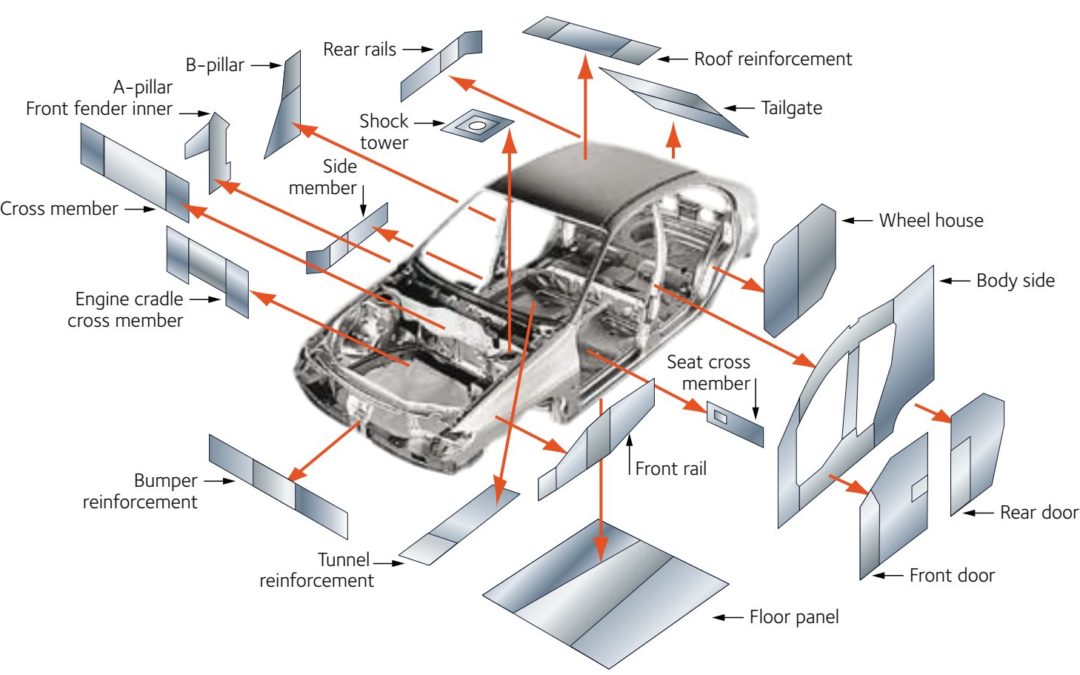
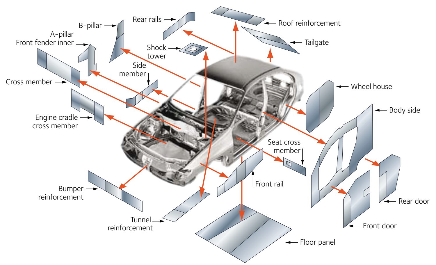
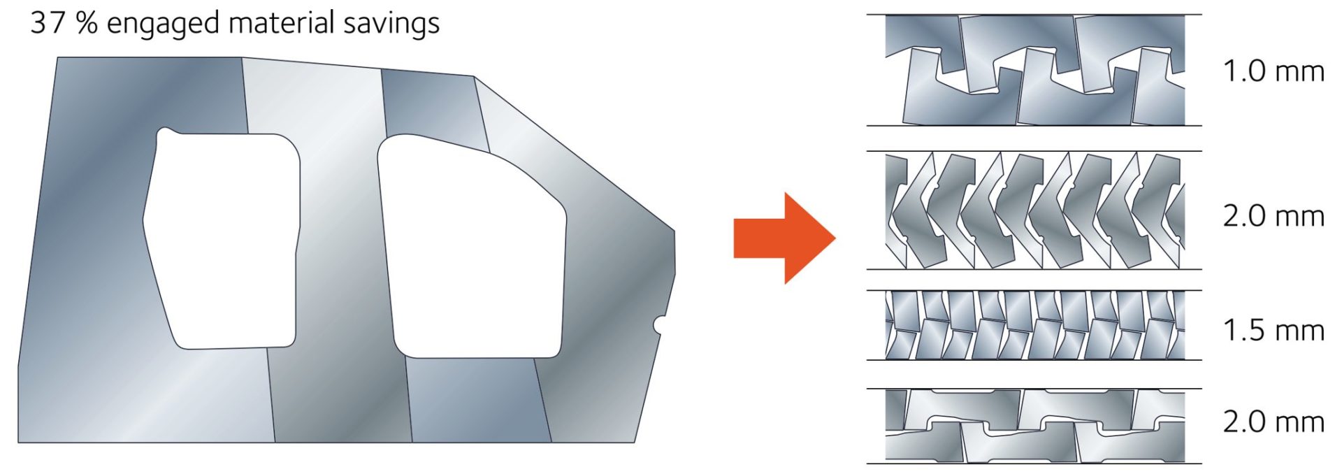
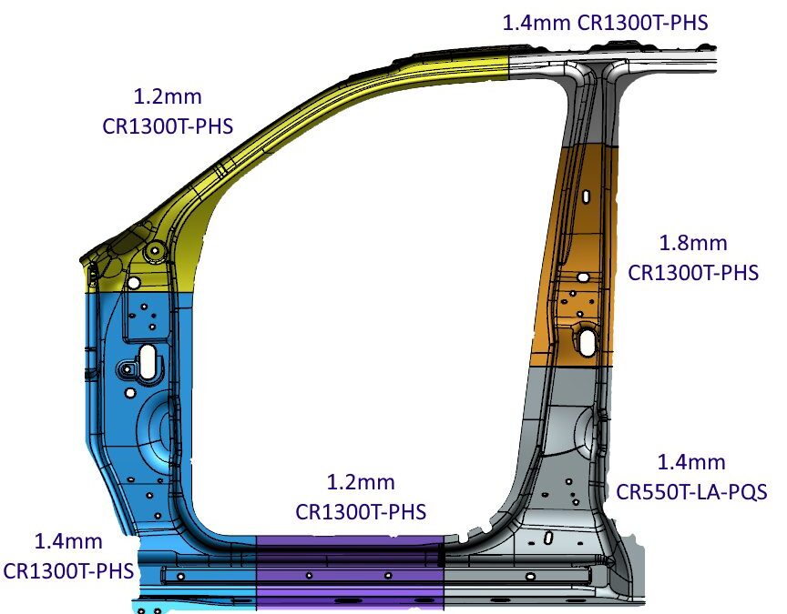
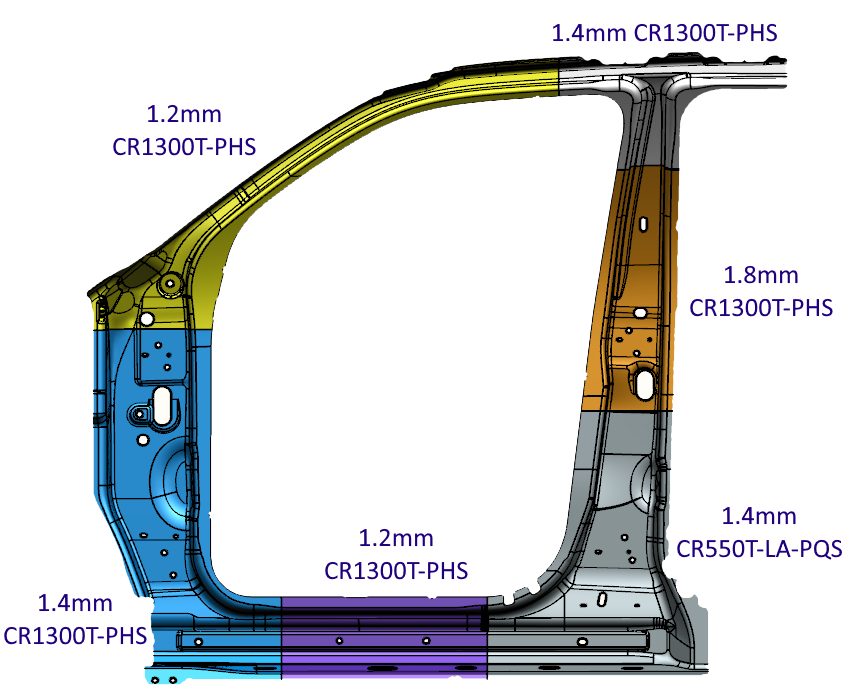
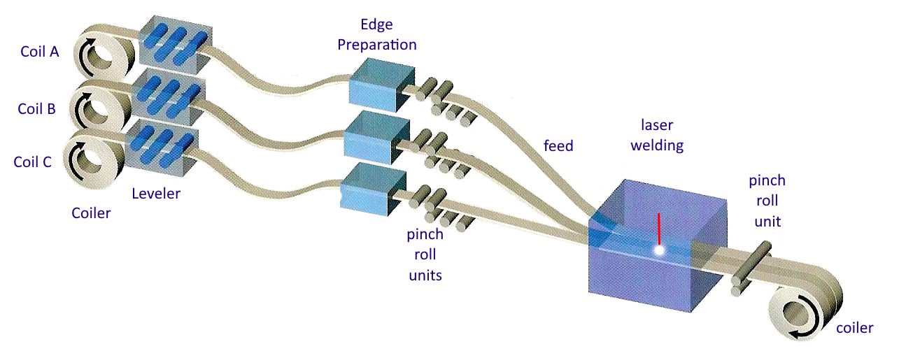
![Figure 3: General usage of Tailor Welded Coils [S-28]](https://ahssinsights.org/wp-content/uploads/2020/07/tailor-welded-cole-common-use.jpg)
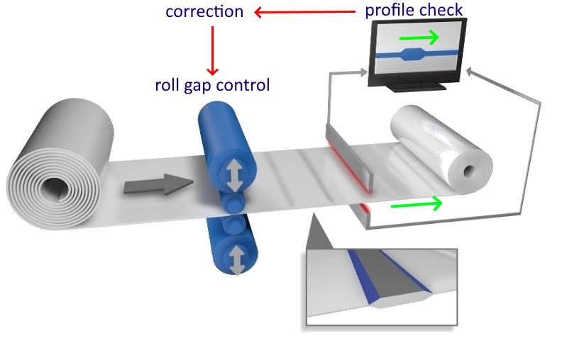
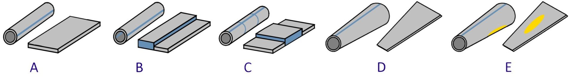
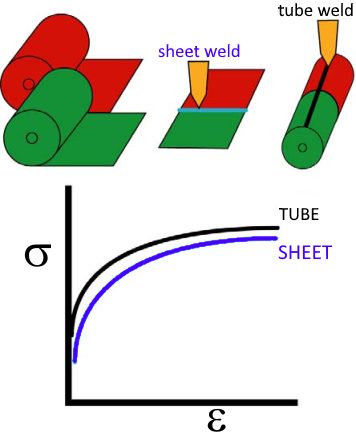
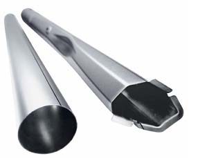

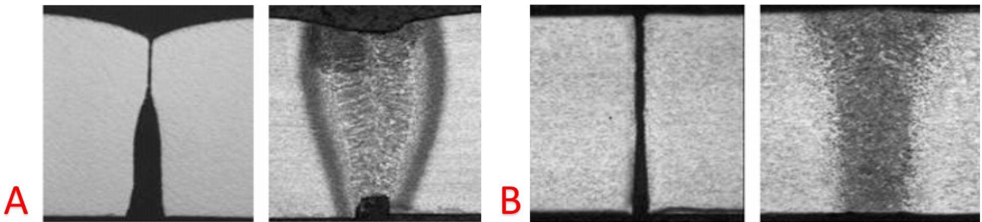
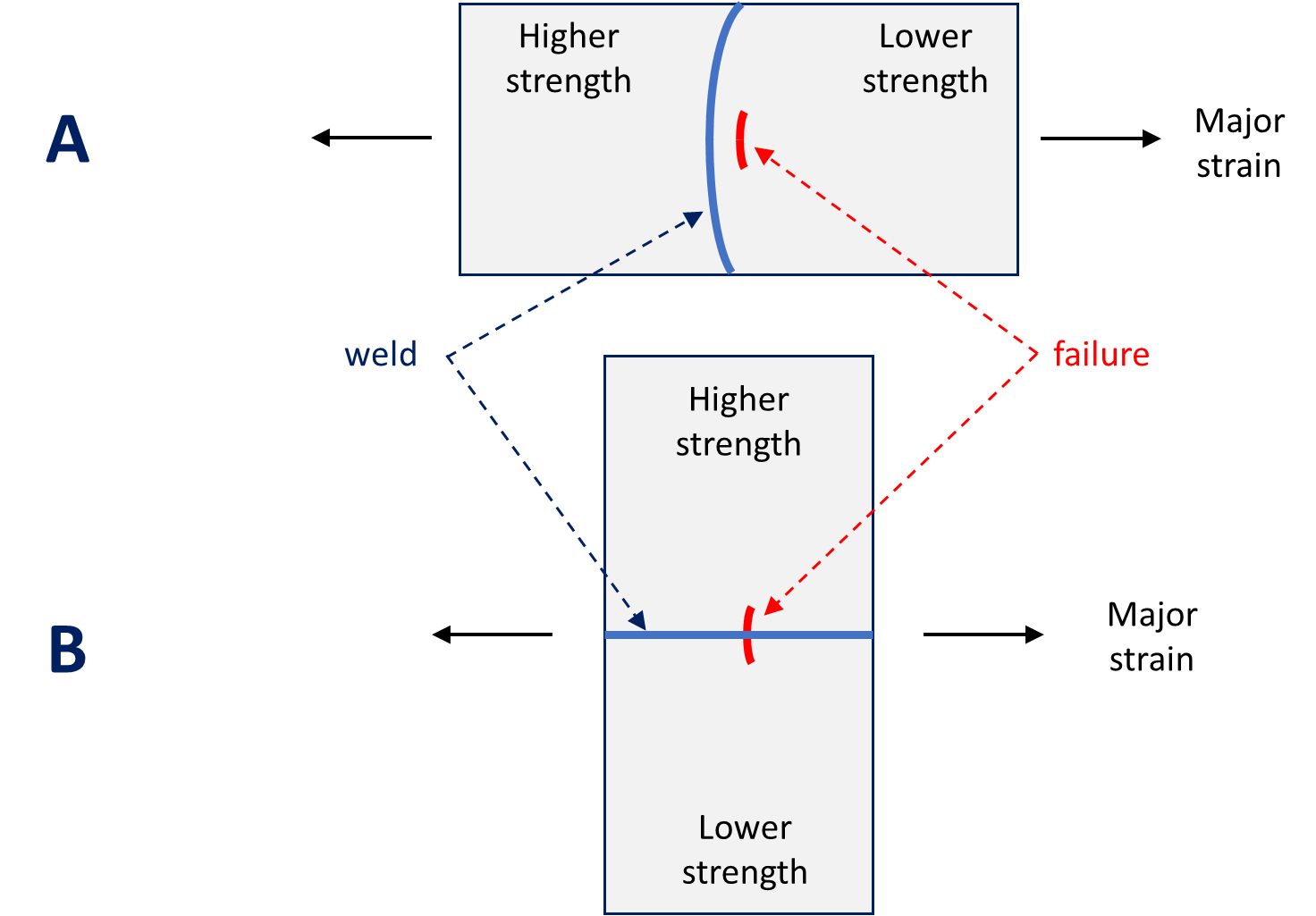
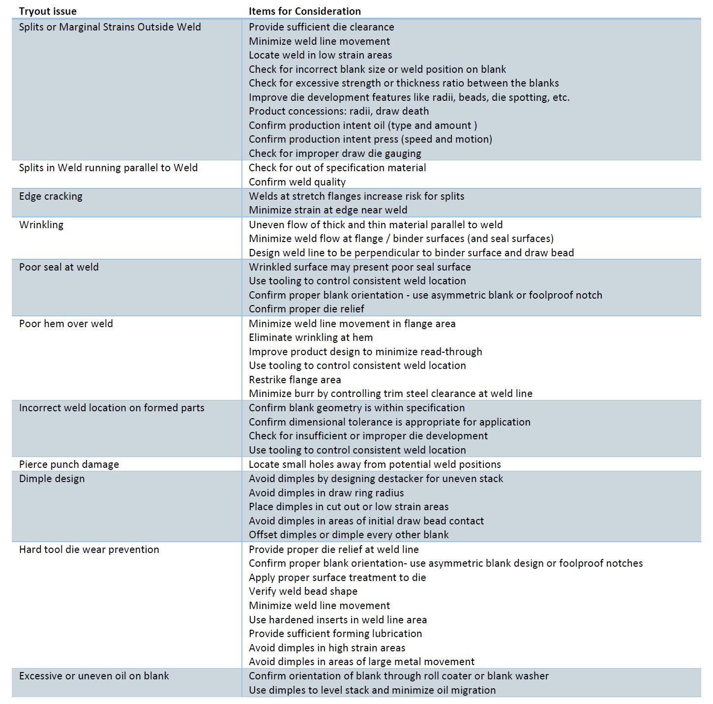
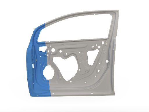
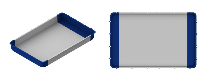
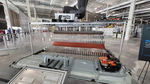


![Figure 12: Double door ring of Tesla Cybertruck: (a) approximate dimensions of the inner part (image re-created after [3]M-72), (b) schematic of outer ring and (c) inner ring (re-created after [4]=F-49).](https://ahssinsights.org/wp-content/uploads/2025/09/PHS-TailoredProps-Figure-12.svg)
![Figure 13: Double door ring applications: (a) GAC Aion UT (SOP 2025) [5]=G-50, (b) Lynk & Co 900 (SOP 2025) [6]=P-30.](https://ahssinsights.org/wp-content/uploads/2025/09/PHS-TailoredProps-Figure-13.svg)


![Figure 18: Sample automotive applications of patchwork PHS: B-pillar reinforcements of (a) 2007 Volvo V70 (re-crated after Citation N-4), (b) 2007 Fiat 500 (re-created after Citation Z-13); and (c) rear rail of 2015 Fiat Tipo/Egea (Citation T-43, recreated after Citation B-14); and (d) door ring of 2022 Voyah Dream (re-created after Citation [13]).H-70](https://ahssinsights.org/wp-content/uploads/2025/09/PHS-TailoredProps-Figure-18.svg)


![Figure 24: Soft zone applications to improve weld quality: (a) Mercedes EQE SUV [15]=D-47, and (b) Renault 5 BEV [14]=G-53.](https://ahssinsights.org/wp-content/uploads/2025/09/PHS-TailoredProps-Figure-24.svg)


