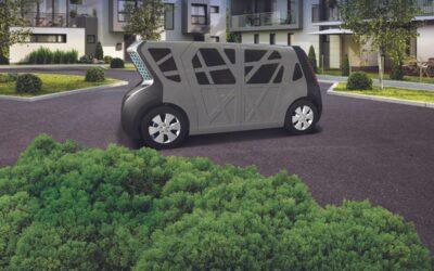
Urbanization and waning interest in vehicle ownership point to new transport opportunities in megacities around the world. Mobility as a Service (MaaS) – characterized by autonomous, ride-sharing-friendly EVs – can be the comfortable, economical, sustainable transport...
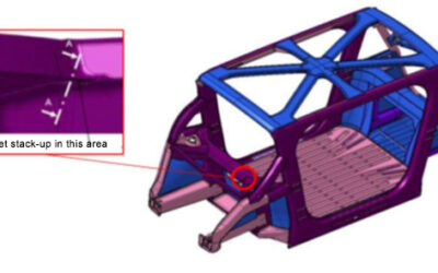
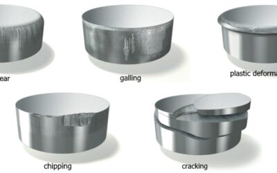
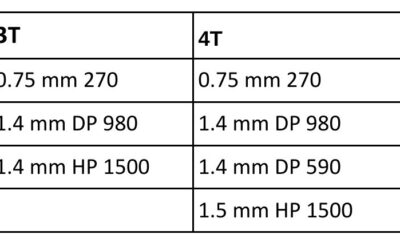
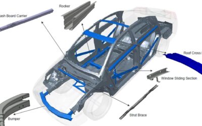
Resistance Spot Welding: 5T Dissimilar Steel Stack-ups for Automotive Applications
read more