As an organization focused on advancing the advantages of steel to the automotive, autonomous vehicle, and future mobility industries, WorldAutoSteel is committed to engaging with future engineers at universities and colleges around the globe.
Our most recent engineering project, Steel E-Motive, was designed to unveil and meet the challenges of future autonomous vehicles that will help the automotive industry reach net zero emissions targets.
For the Steel E-Motive project, we engaged Ricardo plc to collaborate with our technical directors to develop a Level 5 Autonomous Vehicle. The project uncovered a few challenges that were solved by student engineering teams through Senior Capstone Projects.
Here we summarize the Side Door and Door Hinges project, created at Michigan Technological University by the students and faculty members listed herein.
Steel E-Motive Side Door Functionality and Door Hinge Assessment
The MTU Senior Capstone Team members were Gavin Sheffer, Leander Daavettila, Rob Oestreich, Steven Turnbull, Andrew Mitteer, and Jesse Ebenhoeh.
Introduction and Background
The MTU Senior Capstone Design Team, sponsored by WorldAutoSteel and the Auto/Steel Partnership, was challenged to design a new door hinge for the Steel E-Motive side closure mechanism. The current hinge design was referenced, but a few operational issues were identified for this team’s assessment and engineering study.
The door had unconstrained degrees of freedom, allowing it to swing freely about one axis. Thus, the project included a review of the kinematics of the door opening and hinge design for attachment to the A and C pillars.
The previous hinge design interferes with the all-wheel steering, meaning in emergency situations, passengers could get trapped in the vehicle. For SEM1, it was also observed that when the wheels are turned, they would block the doors from opening fully, constraining the passenger exit (Figure 1 below).
An emergency release mechanism was needed to allow users to escape if a crash or electrical failure prevented the doors from opening. Power requirements and electric motor sizing for the hinge mechanism needed to be defined.
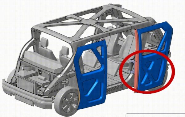
Figure 1: Side door opening constrained by present hinge mechanism and wheel position.
Project Details and Results – Autonomous Vehicle Solutions
MTU’s design solution uses a four-bar linkage hinge design to keep the door parallel to the vehicle’s body to avoid damage to either the door or the body. The team used a 4:1 gear ratio for the drive motor to open the door. Finally, one of the pins in the secondary arm linkage is accessible by passengers and removable, allowing users to manually push the door open in the event of an emergency (see Figure 2).
Their solution includes pressing a button to open and close the door. The stepper motor receives the input from the button and rotates the gears; the gears then rotate the primary arm, which drives the door. The primary arm is mounted to the door in two locations with bolts. The secondary arm is added to the mechanism to create a four-bar linkage, which helps maintain door orientation during operation. An emergency release was designed and added to the secondary arm to release the four-bar linkage. This allows the door to swivel around a turned wheel in the event of an emergency.
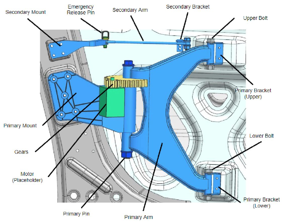
Figure 2: 3D model of the final design less the gear cover for clarity.
The emergency release was designed for safety and manufacturability of the autonomous vehicle. The emergency release pin was simplified to utilize off-the-shelf pins. A relay is suggested to cut power to the motor and allow the door to be manually pushed open. A gear cover was added for safety to protect the occupants from getting pinched by the gears. To maintain and service the design, each assembly part was designed to be attached with threaded fasteners. A gear drive was created so we could use a more cost-efficient motor. The gear ratio decreased the amount of torque required. The material was chosen based on strength and sustainability.
Conclusions
The CAD geometry and the quarter-scale prototype met all of our engineering requirements and objectives. The CAD model defines the mass and emergency release mechanism, and the kinematics are verified by the quarter-scale prototype. The FEA simulation verified set and sag under normal and abusive loading conditions.
In identifying specifications required for the full model, the projected production cost for one mechanism is $471. This includes stamped and cast components, off-the-shelf components such as the stepper motor and fasteners, and the assembly cost.
The team compared using AHSS for the components as opposed to an aluminum alloy. Steel components are stronger, half the price of aluminum, and produce 1/3 of the carbon emissions compared to the same amount of aluminum.
The prototype was 3D printed from PLA plastic at a quarter scale. This serves as a model to be shown by Auto/Steel Partnership for future presentations. It was also used to verify the kinematics of the door motion.
Learn more about Steel E-Motive and download the FREE Engineering Report here: Steel E-Motive