“Bainitizing, 20MnB8, 22MnB5, 22MnSiB9-5, AlSi, Bainitizing, Blog, BQP, direct press hardening, furnace, grades, high ductility PHS, homepage-featured-top, indirect press hardening, main-blog, Manganese-Boron, multi-step press hardening, PHS, PQS, pre-cooled stamping, Press Hardened Steels, Press Hardening Steel, Press Quenched Steel, Quenching and Partitioning”, SIBORA, Unisteel
You’ll find most of this content as part of our page on Press Hardening Steel Grades, but this month, we want to highlight it in our AHSS Insights blog. Thanks to Eren Billur, Ph.D., President, Billur Metal Form, for providing this information.
What Are Press Hardening Steel Grades and How Are They Made?
Press hardening is a special hot forming process, where the part is quenched in a forming die to receive its high hardness. It has been used in the automotive industry for over 40 years now.
The most common press hardening steel (PHS) is 22MnB5, a low carbon steel with Manganese-Boron alloying. Since it achieves a typical tensile strength of 1500 MPa after heat treatment, this material is mostly named as PHS1500 or CR1500T-MB (Cold Rolled, 1500 MPa typical Tensile strength, Manganese-Boron alloyed).B-14, V-19
The Direct Press Hardening Steel Process
The direct press hardening process involves heating the blanks over 900°C (1650°F) in an industrial furnace. The blanks are then removed from the furnace and quickly transferred to a forming die. The formed parts are not removed immediately. Instead, they are kept under force in a water-cooled tool set for quenching. With a 22MnB5 steel, the quenched part typically reaches 1500 MPa tensile strength. B-14
Coatings and Early Process Enhancements
Over the years, the first improvement on the 22MnB5 material was the application of an aluminum-silicon coating around early 2000’s. The addition of the coating did not affect its strength or elongation but improved the process as it eliminated scale formation during forming and quenching. AlSi coating however limited the process to the aforementioned direct process.B-14
Zinc Coatings and the Indirect Process
Some OEMs, especially in Europe, wanted to use Zn-based coatings for corrosion protection. The typical 22MnB5 is available with hot-dip galvanized (GI) and galvannealed (GA) coatings. Liquid metal embrittlement (LME) with Zn-based coatings is avoided with an indirect press hardening process. Forming is done at ambient temperatures, with the part subsequently heated and quenched in a press tool. These materials and techniques have been available since 2008.P-5
Figure 1 summarizes the most common 22MnB5 grades and coatings before and after the press hardening process.
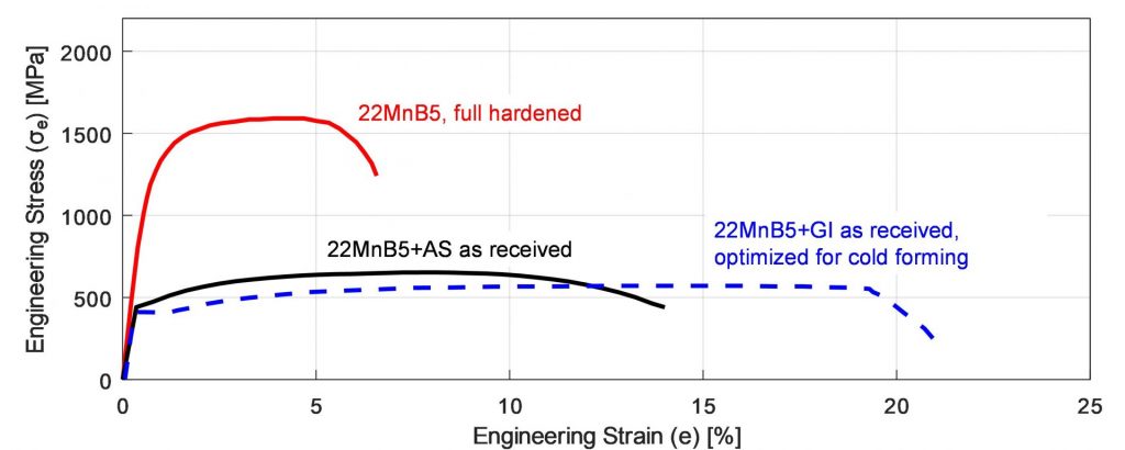
Figure 1: 22MnB5 before and after the hot stamping and quenching cycle. The incoming material is similar to HSLA 380 or DP600 and can be cold formed if needed. After hot stamping, typical tensile strength is around 1500 MPa (re-created after: B-18, O-8, U-9).
Measuring Performance: VDA Standards
In 2010, German Association of the Automotive Industry (VDA) developed a new bending test (238-100) to evaluate energy absorbing capacity of PHS and PQS grades.V-4 This test gave a “bending angle” measurement, which replaced – to some extent – the use of “total elongation” value for energy absorbing calculations.
PHS1800 and Beyond
In 2011, a Japanese steel maker developed the first 1800 MPa (typical) tensile strength material. The material was AlSi coated with a modified, higher carbon, 30MnB5 chemistry and Nb alloying.H-33 One Japanese OEM applied the material in their bumper beams. The higher strength allowed using 1.4 mm thick PHS1800 material, instead of 1.6 mm PHS1500.M-28
Tailored Solutions for Specific Applications
A German OEM designed a B-pillar with a PHS1500 upper section, laser welded to a lower section formed from HSLA 340LA (340 MPa yield strength) steel for improved energy absorption.S-13 It was later found that typical HSLA steels not designed for hot stamping process may show significant variation in mechanical properties depending on the cooling rate.D-22
The Rise of Press Quenched Steels (PQS)
Steel companies subsequently developed “Press Quenched Steels” (PQS) which are also HSLA but have been specifically modified to achieve consistent material properties at varying cooling rates.H-69 PQS grades are not hardenable, even after hot stamping and quenching cycle.
These steels were not used in the automotive industry until 2014, and have been commercially available since that time.L-29 These can be named as PQS450 and PQS550 (named after minimum tensile strength) or CR500T-LA and CR600T-LA (named after typical tensile strength, LA stands for Low Alloy).
Expanding Options: Pre-Cooled Steels
In 2015, a steel company in Europe developed 20MnB8 with GI coating. Chemistry with slightly lower carbon and higher manganese allowed forming to be done at lower temperatures. The company developed a new process route where the heated blank is first pre-cooled to around 500°C (930°F) and then formed and quenched – solving any LME concerns. The grade’s mechanical properties are nearly identical to 22MnB5 after quenching.K-21 Thus, it may be called PHS1500, but to differentiate the material, they are typically named CR1500T-MB-PS (PS stands for Pre-cooled Stamping).V-9
Expanding Options: Composite Steels
In 2016, two different composite steels were developed for hot stamping. These are 3-layers, hot rolled cladded grades with PQS on the outer skin and PHS1500 in the core. These were 1200 and 1400 MPa tensile strength level grades, with significantly improved bendability. There is only a commercial name for this material. To avoid using those names, the grades may be referred to as PHS1200 Sandwich and PHS1400 Sandwich.L-68
Improving Formability and Weldability
Around 2016, steel makers started developing another PHS grade which has 1000-1200 MPa tensile strength after quenching. The grade had almost similar elongation with PHS1500 (almost 5%), but higher bendability (75° vs. 50°). These grades also have lower metallurgical notch effects when spot welded. The material may be named CR1100T-MB.V-9
Multi-Step and Air-Hardening Innovations
In 2019, a Japanese steel company developed “air-hardening” 22MnSiB9-5 alloy with GA coating. After hot forming and quenching, the material had mechanical properties almost equivalent to 22MnB5. Thus, this material can also be named as PHS1500. Since the material is air-hardenable, meaning that it hardens even at very low cooling rates, it can be hot formed in a multi-station servo-mechanical-transfer press [16]. The technique is then named as “multi-step hot forming”, with the grade referred to as CR1500T-MB-MS (the last MS stands for Multi-Step).V-9
Ultra High Strength and the VDA Naming System
Since 2020, steel companies rolled out 1900 or 2000 MPa (typical) tensile strength materials. These grades are now commonly referred to as CR1900T-MB. These grades are already available uncoated, AlSi coated or GA coated.V-9
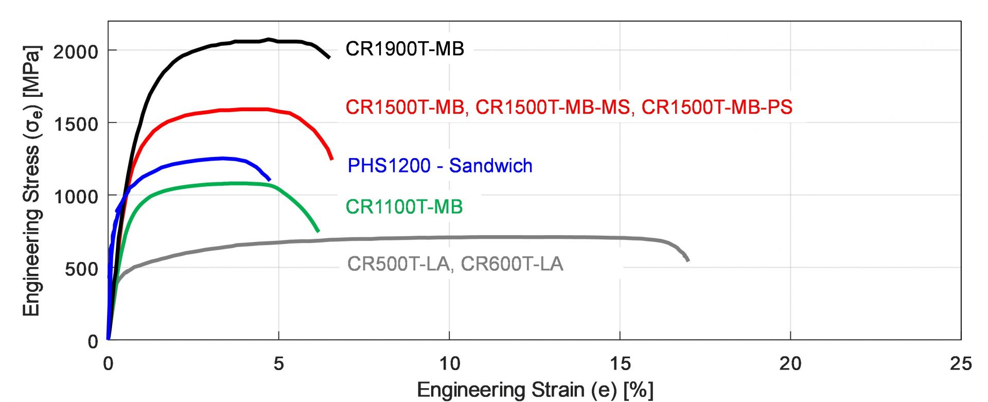
In 2021, VDA published a new standard (239-500), which standardizes the naming, chemistry and mechanical properties of PHS and PQS grades. All the grades shown in Figure 2 (excluding the sandwich) are named based on this VDA standard.V-9
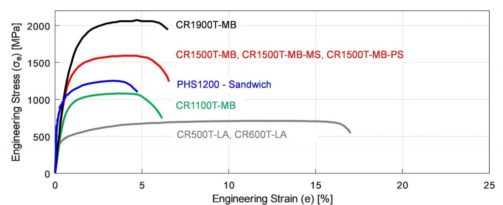
Figure 2: Stress-strain curves of commercially available PHS and PQS grades after quenching. (re-created after: B-18,Y-12, R-14).
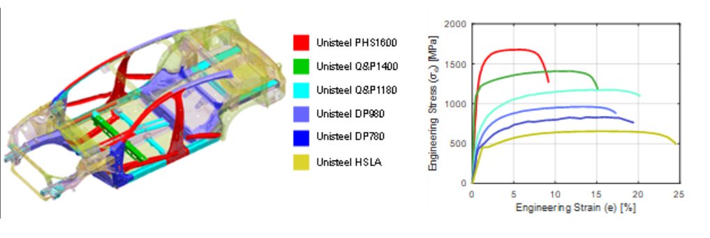
The UniSteel Concept: One Alloy, Many Properties
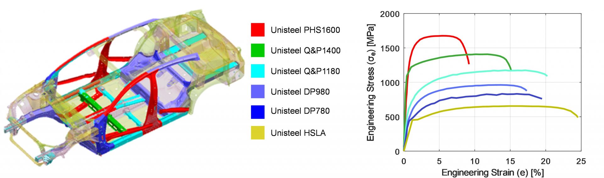
In late 2021, researchers from China came up with a concept of using one chemistry (a modified 22MnB5) combined with different thermal processes to tailor the production of differing mechanical properties. Thus, it became possible to make a whole car from the same alloy, named as “UniSteel”. The different properties and their use areas are shown in Figure 3. The research was published in Science magazine.L-68

Figure 3: UniSteel concept: (a) material usage in a car body, (2) mechanical properties after heat treatments (re-created after R-14)
The Future: BQP and SIBORA Development
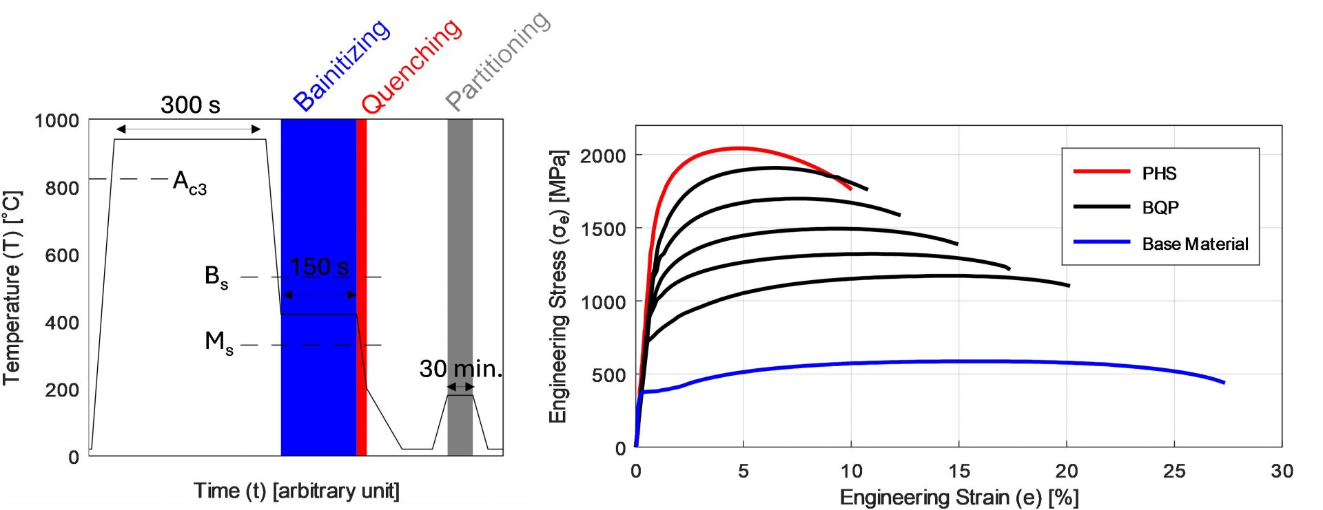
In 2025, a German consortium developed a new grade 37SiB6 and a new process route called Bainitizing, Quenching and Partitioning (BQP). Similar to the Chinese UniSteel concept, the new SIBORA (Silicon Boron with Retained Austenite) material can have various strength and elongation levels. Both the process and resulting mechanical properties are given in Figure 4. Different strength levels can be achieved by changing the bainitizing temperature between 360 and 460°C (680 and 860°F).O-15
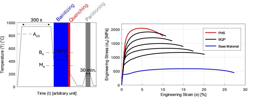
Figure 4: (a) the BQP process (shown here is 360°C bainitizing temperature), (b) the mechanical properties after PHS or BQP processes (re-created after O-15).
We encourage you to visit this steel grades page to learn more about these grades available for Press Hardening, and head to this PHS and PQS Overview page for our PHS Primer. Thank you to Eren Billur for providing this information.
 Thanks go to Eren Billur, Ph.D. for his contribution of this article to the AHSS Insights blog. Eren Billur is the Technical Manager of Billur Makine and Billur Metal Form, based in Ankara, Turkey, specializing in advanced sheet metal forming technologies. He holds a Ph.D. in Mechanical Engineering from The Ohio State University and has extensive experience in material characterization, sheet metal forming processes, and finite element simulations. Eren has contributed significantly to the understanding and application of hot stamping and advanced high-strength steels (AHSS) in the automotive industry. He is a regular columnist for MetalForming Magazine’s “Cutting Edge” column and has authored numerous scientific papers and book chapters, including contributions to the WorldAutoSteel AHSS Applications Guidelines. Passionate about advancing manufacturing knowledge, Eren provides engineering consulting, training, and simulation services worldwide, helping manufacturers optimize forming processes and successfully implement new-generation AHSS materials.

AHSS, Blog, homepage-featured-top, Joining, Joining Dissimilar Materials, main-blog, Steel Grades
The discussions relative to cold stamping are applicable to any forming operation occurring at room temperature such as roll forming, hydroforming, or conventional stamping. Similarly, hot stamping refers to any set of operations using Press Hardening Steels (or Press Quenched Steels), including those that are roll formed or fluid formed.
Automakers contemplating whether a part is cold stamped or hot formed must consider numerous factors. This blog covers some important considerations related to welding these materials for automotive applications. Most important is the discussion on Resistance Spot Welding (RSW) as it is the dominating process in automotive manufacturing.
Setting Correct Welding Parameters for Resistance Spot Welding
Specific welding parameters need to be developed for each combination of material type and thickness. In general, the Hot Press (HP) steels require more demanding process conditions. One important factor is electrode force which should be higher for the HP steel than for cold press type steel of the same thickness. The actual recommended force will depend on the strength level, and the thickness of the steel. Of course, this will affect the welding machine/welding gun force capability requirement.
Another important variable is the welding current level and even more important is the current range at which acceptable welds can be made. The current range is weldability measurement, and the best indicator of the welding process robustness in the manufacturing environment and sometime called proceed window. Note the relative range of current for different steel types. A smaller process window may require more frequent weld quality evaluation such as for weld size.
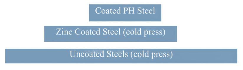
Relative Current Range (process windows) for Different Steel Types
The Effect of Coating Type on Weldability
In all cases of resistance spot welding coated steels, it is imperative to move the coating away from the weld area during and in the beginning of the weld cycle to allow a steel-to-steel weld to occur. The combination of welding current, weld time and electrode force are responsible for this coating displacement.
For all the coated steels, the ability of the coating to flow is a function of the coating type and properties, such as electrical resistivity and melting point, as well as the coating thickness.
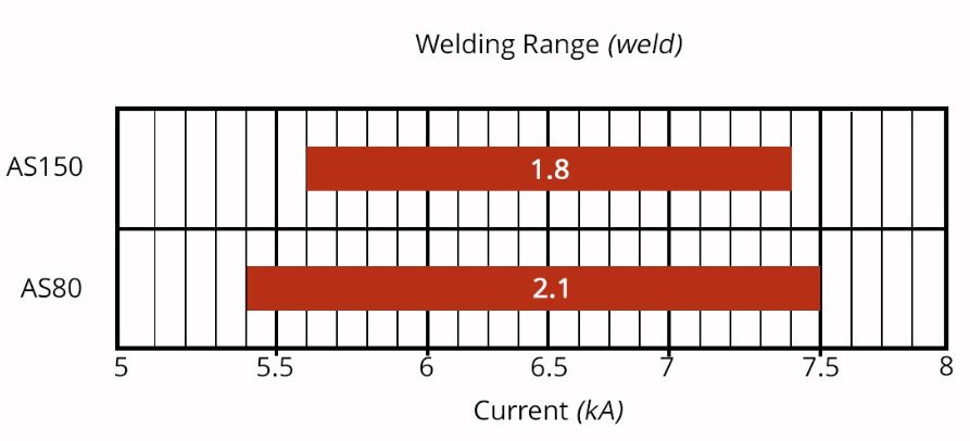
An example of cross sectioned spot welds made on Hot Press Steel with Aluminum -Silicon coating is shown below. It shows two coating thicknesses and the displaced coating at the periphery of weld. This figure also shows the difference in current range for the different coating thickness. The thicker coating shows a smaller current range. In addition, the Al-Si coating has a much higher melting point than the zinc coatings on the cold stamped steels, making it more difficult to displace from the weld area.
Hot Press Steel with Aluminum -Silicon
Liquid Metal Embrittlement and Resistance Spot Welding
Cold-formable, coated, Advance High Strength Steels such as the 3rd Generation Advanced High Strength Steels are being widely used in automotive applications. One welding issue these materials encounter is the increased hardness in the weld area, that sometime results in brittle fracture of the weld.
Another issue is their sensitivity to Liquid Metal Embrittlement (LME) cracking. These two issues are discussed in detail on the WorldAutoSteel AHSS Guidelines website and our recently released Phase 2 Report on LME.
Resistance Spot Welding Using Current Pulsation
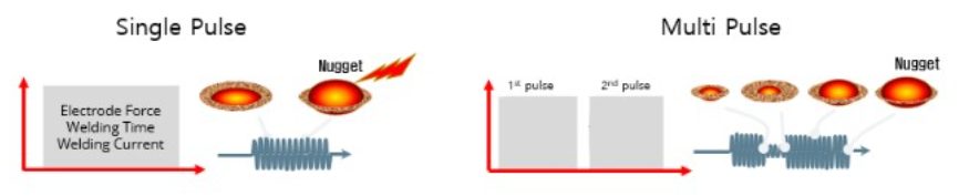
The most effective solution for the issues described above is using current pulsation during the welding cycle. A schematic description is shown below.
The pulsation allows much better control of the heat generation and the weld nugget development. The pulsation variables include the number of pulses (typically 2-4), the current level and time for each pulse, and the cool time between the pulses.
In summery, pulsation (and sometime current upslope) in Resistance Spot Welding proved to be beneficial for the following applications:
- Coated Cold Stamped steels
- Cold stamped Advance High Strength Steels
- Multi materials stack-ups – As described in our articles here on 3T/4T and 5T Stack-Ups

Thanks is given to Menachem Kimchi, Associate Professor-Practice, Dept of Materials Science, Ohio State University and Technical Editor – Joining, AHSS Application Guidelines, for this article.

Blog, homepage-featured-top, main-blog
Grade Options and Corrosion Protection Considerations When Deciding How A Part Gets Formed
Automakers contemplating whether a part is cold stamped or hot formed must consider numerous ramifications impacting multiple departments. Our prior blog on this topic highlighted the equipment differences and the property development differences between each approach. We continue this blog series, now focusing on grade options and corrosion protection.
The discussions below relative to cold stamping are applicable to any forming operation occurring at room temperature such as roll forming, hydroforming, or conventional stamping. Similarly, hot stamping refers to any set of operations using Press Hardening Steels (or Press Quenched Steels), including those that are roll formed or fluid-formed.
Grade Options for Cold Stamped or Hot Formed Steel
There are two types of parts needed for vehicle safety cage applications: those with the highest strength that prevent intrusion, and those with some additional ductility that can help with energy absorption. Each of these types can be achieved via cold stamping or hot stamping.
When it comes to cold stamped parts, many grade options exist at 1000 MPa that also have decent ductility. The advent of the 3rd Generation Advanced High Strength Steels adds to the tally. Most of these top out at 1200 MPa, with some companies offering cold-formable Advanced High Strength Steels with 1400 or 1500 MPa tensile strength. The chemistry of AHSS grades is a function of the specific characteristics of each production mill, meaning that OEMs must exercise diligence when changing suppliers.

Figure 1: Stress-strain curve of industrially produced QP980.W-35
Martensitic grades from the steel mill have been in commercial production for many years, with minimum strength levels typically ranging from 900 MPa to 1470 MPa, depending on the grade. These products are typically destined for roll forming, except for possibly those at the lower strengths, due to limited ductility. Until recently, MS1470, a martensitic steel with 1470 MPa minimum tensile strength, was the highest strength cold formable option available. New offerings from global steelmakers now include MS1700, with a 1700 MPa minimum tensile strength, as well as MS 1470 with sufficient ductility to allow for cold stamping. Automakers have deployed these grades in cold stamped applications such as crossmembers and roof reinforcements.

Figure 2: Cold-Stamped Martensitic Steel with 1500 MPa Tensile Strength used in the Nissan B-Segment Hatchback.K-57
Until these recent developments, hot stamping was the primary option to reach the highest strength levels in part shapes having even mild complexity. Under proper conditions, a chemistry of 22MnB5 could routinely reach a nominal or aim strength of 1500 MPa, which led to this grade being described as PHS1500, CR1500T-MB, or with similar nomenclature. Note that in this terminology, 1500 MPa nominal strength typically corresponds to a minimum strength of 1300 MPa.
The 22MnB5 chemistry is globally available, but the coating approaches discussed below may be company-specific.
Newer PHS options with a modified chemistry and subsequent processing differences can reach nominal strength levels of 2000 MPa. Other options are available with additional ductility at strength levels of 1000 MPa or 1200 MPa. A special class called Press Quenched Steels have even higher ductility with strength as low as 450 MPa.
The spectrum of grades available for cold-stamped and hot formed steel parts allows automakers to fine-tune the crash energy management features within a body structure, contributing to steel’s “infinite tune-ability” capability which gives automotive engineers design flexibility and freedoms not available from other structural materials.
Corrosion Protection
Uncoated versions of a grade must take a different chemistry approach than the hot dip galvanized (GI) or hot dipped galvannealed (HDGA) versions since the hot dip galvanizing process acts as a heat treatment cycle that changes the properties of the base steel. Steelmakers adjust the base steel chemistry to account for this heat treatment to ensure the resultant properties fall within the grade requirements.

Figure 3: Schematic of a typical hot-dipped galvanizing line with galvanneal capability.
This strategy has limitations as it relates to grades with increasing amounts of martensite in the microstructure. Complex thermal cycles are needed to produce the highly engineered microstructures seen in advanced steels. Above a certain strength level, it is not possible to create a GI or HDGA version of that grade.
For example, when discussing fully martensitic grades from the steel mill, hot dip galvanizing is not an option. If a martensitic grade needs corrosion protection, then electrogalvanizing is the common approach since an EG coating is applied at ambient temperature, which is low enough to avoid negatively impacting the properties. Automakers might choose to forgo a galvanized coating if the intended application is in a dry area that is not exposed to road salt.

Figure 4: Schematic of an electrogalvanizing line.
For press hardening steels, coatings serve multiple purposes. Without a coating, uncoated steels will oxidize in the austenitizing furnace and develop scale on the surface. During hot stamping, this scale layer limits efficient thermal transfer and may prevent the critical cooling rate from being reached. Furthermore, scale may flake off in the tooling, leading to tool surface damage. Finally, scale remaining after hot stamping is typically removed by shot blasting, an off-line operation that may induce additional issues.
Using a hot dip galvanized steel in a conventional direct press hardening process (blank -> heat -> form/quench) may contribute to liquid metal embrittlement (LME). Getting around this requires either changing the steel chemistry from the conventional 22MnB5 or using an indirect press hardening process that sees the bulk of the part shape formed at ambient temperatures followed by heating and quenching.
Those companies wishing to use the direct press hardening process can use a base steel having an aluminum-silicon (Al-Si) coating, providing that the heating cycle in the austenitizing furnace is such that there is sufficient time for alloying between the coating and the base steel. Welding practices using these coated steels need to account for the aluminum in the coating, but robust practices have been developed and are in widespread use.
For more information about PHS grades and processing, see our Press Hardened Steel Primer.

Danny Schaeffler is the Metallurgy and Forming Technical Editor of the AHSS Applications Guidelines available from WorldAutoSteel. He is founder and President of Engineering Quality Solutions (EQS). Danny wrote the monthly “Science of Forming” and “Metal Matters” column for Metalforming Magazine, and provides seminars on sheet metal formability for Auto/Steel Partnership and the Precision Metalforming Association. He has written for Stamping Journal and The Fabricator, and has lectured at FabTech. Danny is passionate about training new and experienced employees at manufacturing companies about how sheet metal properties impact their forming success.
Blog, homepage-featured-top, main-blog
Equipment, Responsibilities, and Property Development Considerations When Deciding How A Part Gets Formed
Automakers contemplating whether a part is cold stamped or hot formed must consider numerous ramifications impacting multiple departments. Over a series of blogs, we’ll cover some of the considerations that must enter the discussion.
The discussions relative to cold stamping are applicable to any forming operation occurring at room temperature such as roll forming, hydroforming, or conventional stamping. Similarly, hot stamping refers to any set of operations using Press Hardening Steels (or Press Quenched Steels), including those that are roll formed or fluid-formed.
Equipment
There is a well-established infrastructure for cold stamping. New grades benefit from servo presses, especially for those grades where press force and press energy must be considered. Larger press beds may be necessary to accommodate larger parts. As long as these factors are considered, the existing infrastructure is likely sufficient.
Progressive-die presses have tonnage ratings commonly in the range of 630 to 1250 tons at relatively high stroke rates. Transfer presses, typically ranging from 800 to 2500 tons, operate at relatively lower stroke rates. Power requirements can vary between 75 kW (630 tons) to 350 kW (2500 tons). Recent transfer press installations of approximately 3000 tons capacity allow for processing of an expanded range of higher strength steels.
Hot stamping requires a high-tonnage servo-driven press (approximately 1000 ton force capacity) with a 3 meter by 2 meter bolster, fed by either a roller-hearth furnace more than 30 m long or a multi-chamber furnace. Press hardened steels need to be heated to 900 °C for full austenitization in order to achieve a uniform consistent phase, and this contributes to energy requirements often exceeding 2 MW.
Integrating multiple functions into fewer parts leads to part consolidation. Accommodating large laser-welded parts such as combined front and rear door rings expands the need for even wider furnaces, higher-tonnage presses, and larger bolster dimensions.
Blanking of coils used in the PHS process occurs before the hardening step, so forces are low. Post-hardening trimming usually requires laser cutting, or possibly mechanical cutting if some processing was done to soften the areas of interest.
That contrasts with the blanking and trimming of high strength cold-forming grades. Except for the highest strength cold forming grades, both blanking and trimming tonnage requirements are sufficiently low that conventional mechanical cutting is used on the vast majority of parts. Cut edge quality and uniformity greatly impact the edge stretchability that may lead to unexpected fracture.
Responsibilities
Most cold stamped parts going into a given body-in-white are formed by a tier supplier. In contrast, some automakers create the vast majority of their hot stamped parts in-house, while others rely on their tier suppliers to provide hot stamped components. The number of qualified suppliers capable of producing hot stamped parts is markedly smaller than the number of cold stamping part suppliers.
Hot stamping is more complex than just adding heat to a cold stamping process. Suppliers of cold stamped parts are responsible for forming a dimensionally accurate part, assuming the steel supplier provides sheet metal with the required tensile properties achieved with a targeted microstructure.
Suppliers of hot stamped parts are also responsible for producing a dimensionally accurate part, but have additional responsibility for developing the microstructure and tensile properties of that part from a general steel chemistry typically described as 22MnB5.
Property Development
Independent of which company creates the hot formed part, appropriate quality assurance practices must be in place. With cold stamped parts, steel is produced to meet the minimum requirements for that grade, so routine property testing of the formed part is usually not performed. This is in contrast to hot stamped parts, where the local quench rate has a direct effect on tensile properties after forming. If any portion of the part is not quenched faster than the critical cooling rate, the targeted mechanical properties will not be met and part performance can be compromised. Many companies have a standard practice of testing multiple areas on samples pulled every run. It’s critical that these tested areas are representative of the entire part. For example, on the top of a hat-section profile where there is good contact between the punch and cavity, heat extraction is likely uniform and consistent. However, on the vertical sidewalls, getting sufficient contact between the sheet metal and the tooling is more challenging. As a result, the reduced heat extraction may limit the strengthening effect due to an insufficient quench rate.
For more information, see our Press Hardened Steel Primer to learn more about PHS grades and processing!
Thanks are given to Eren Billur, Ph.D., Billur MetalForm for his contributions to the Equipment section, as well as many of the webpages relating to Press Hardening Steels at www.AHSSinsights.org.
Danny Schaeffler is the Metallurgy and Forming Technical Editor of the AHSS Applications Guidelines available from WorldAutoSteel. He is founder and President of Engineering Quality Solutions (EQS). Danny wrote the monthly “Science of Forming” and “Metal Matters” column for Metalforming Magazine, and provides seminars on sheet metal formability for Auto/Steel Partnership and the Precision Metalforming Association. He has written for Stamping Journal and The Fabricator, and has lectured at FabTech. Danny is passionate about training new and experienced employees at manufacturing companies about how sheet metal properties impact their forming success.
Blog, homepage-featured-top, main-blog, Roll Forming
Roll Forming
Case Study: How Steel Properties Influence the Roll Forming Process
Coil Shape Imperfections Influencing Roll Forming
Roll Stamping
Roll Forming takes a flat sheet or strip and feeds it longitudinally through a mill containing several successive paired roller dies, each of which incrementally bends the strip into the desired final shape. The incremental approach can minimize strain localization and compensate for springback. Therefore, roll forming is well suited for generating many complex shapes from Advanced High-Strength Steels, especially from those grades with low total elongation, such as martensitic steel. The following video, kindly provided by Shape Corp.S-104, highlights the process that can produce either open or closed (tubular) sections.
The number of pairs of rolls depends on the sheet metal grade, finished part complexity, and the design of the roll-forming mill. A roll-forming mill used for bumpers may have as many as 30 pairs of roller dies mounted on individually driven horizontal shafts.A-32
Roll forming is one of the few sheet metal forming processes requiring only one primary mode of deformation. Unlike most forming operations, which have various combinations of forming modes, the roll-forming process is nothing more than a carefully engineered series of bends. In roll forming, metal thickness does not change appreciably except for a slight thinning at the bend radii.
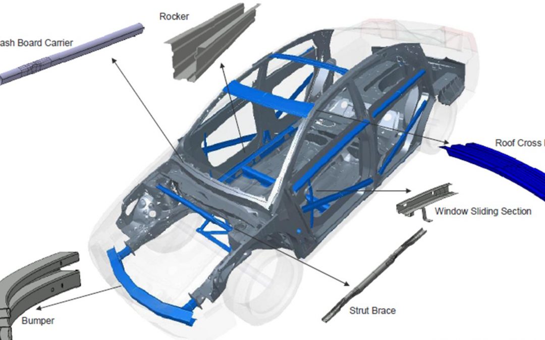
Roll forming is appropriate for applications requiring high-volume production of long lengths of complex sections held to tight dimensional tolerances. The continuous process involves coil feeding, roll forming, and cutting to length. Notching, slotting, punching, embossing, and curving combine with contour roll forming to produce finished parts off the exit end of the roll-forming mill. In fact, companies directly roll-form automotive door beam impact bars to the appropriate sweep and only need to weld on mounting brackets prior to shipment to the vehicle assembly line.A-32 Figure 1 shows an example of automotive applications that are ideal for the roll-forming process.
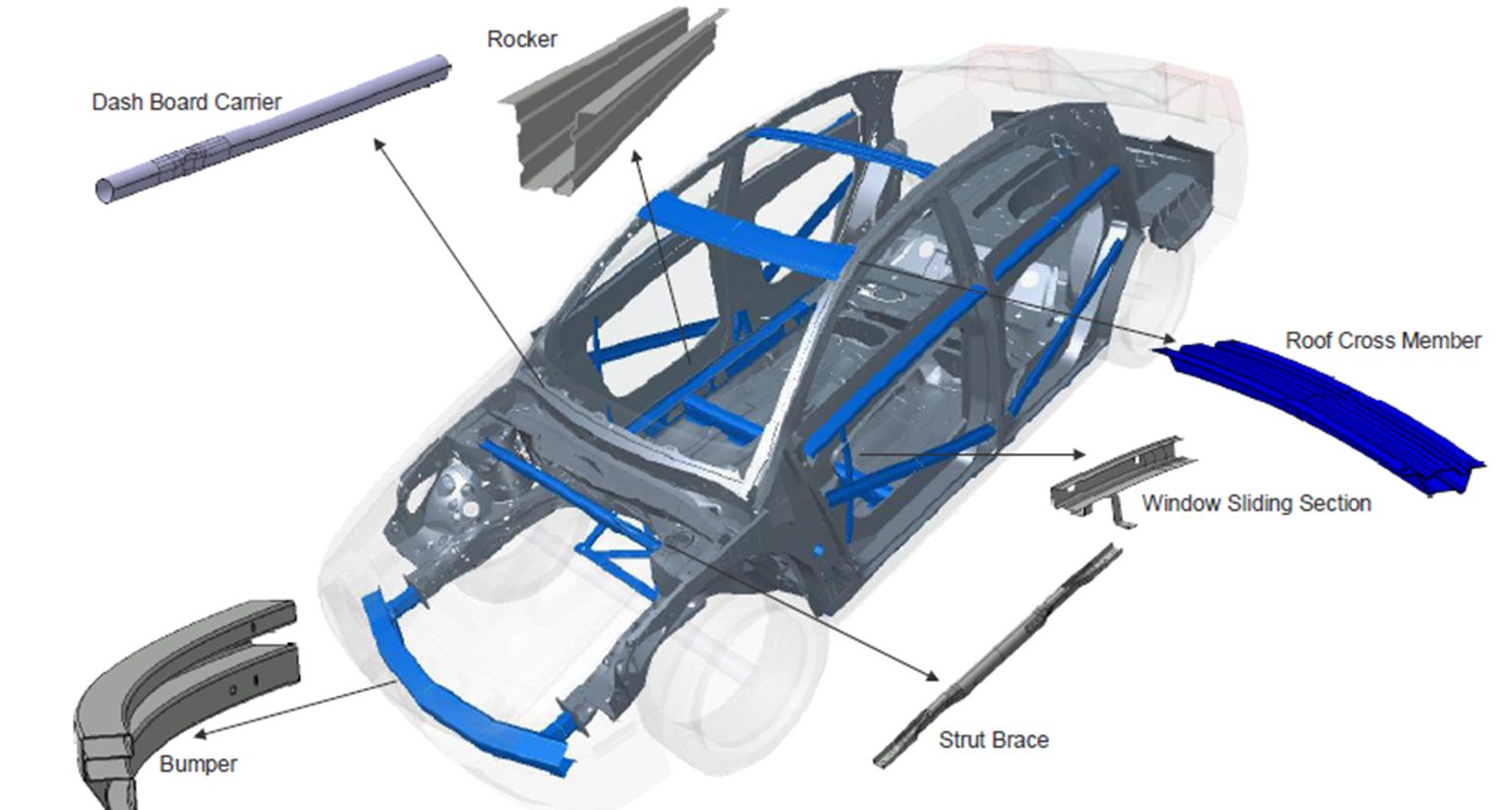
Figure 1: Body components that are ideally suited for roll-forming.
Roll forming can produce AHSS parts with:
- Steels of all levels of mechanical properties and different microstructures.
- Small radii depending on the thickness and mechanical properties of the steel.
- Reduced number of forming stations compared with lower strength steel.
However, the high sheet-steel strength means that forces on the rollers and frames in the roll-forming mill are higher. A rule of thumb says that the force is proportional to the strength and thickness squared. Therefore, structural strength ratings of the roll forming equipment must be checked to avoid bending of the shafts. The value of minimum internal radius of a roll formed component depends primarily on the thickness and the tensile strength of the steel (Figure 2).
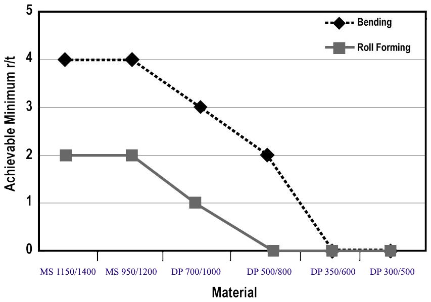
Figure 2: Achievable minimum r/t values for bending and roll forming for different strength and types of steel.S-5
As seen in Figure 2, roll forming allows smaller radii than a bending process. Figure 3 compares CR1150/1400-MS formed with air-bending and roll forming. Bending requires a minimum 3T radius, but roll forming can produce 1T bends.S-30
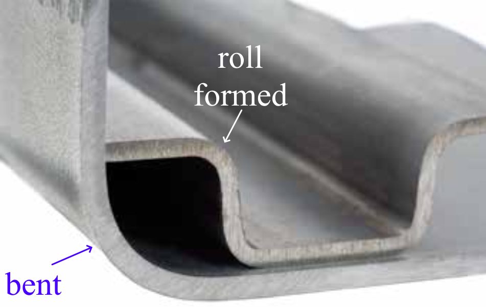
Figure 3: CR1150/1400-MS (2 mm thick) has a minimum bend radius of 3T, but can be roll formed to a 1T radius.S-30
The main parameters having an influence on the springback are the radius of the component, the sheet thickness, and the strength of the steel. As expected, angular change increases for increased tensile strength and bend radius (Figure 4).

Figure 4: Angular change increases with increasing tensile strength and bend radii.A-4
Figure 5 shows a profile made with the same tool setup for three steels at the same thickness having tensile strength ranging from 1000 MPa to 1400 MPa. Even with the large difference in strength, the springback is almost the same.

Figure 5: Roll formed profile made with the same tool setup for three different steels. Bottom to Top: CR700/1000-DP, CR950/1200-MS, CR1150/1400-MS.S-5
Citation A-33 provides guidelines for roll forming High-Strength Steels:
- Select the appropriate number of roll stands for the material being formed. Remember the higher the steel strength, the greater the number of stands required on the roll former.
- Use the minimum allowable bend radius for the material in order to minimize springback.
- Position holes away from the bend radius to help achieve desired tolerances.
- Establish mechanical and dimensional tolerances for successful part production.
- Use appropriate lubrication.
- Use a suitable maintenance schedule for the roll forming line.
- Anticipate end flare (a form of springback). End flare is caused by stresses that build up during the roll forming process.
- Recognize that as a part is being swept (or reformed after roll forming), the compression of metal can cause sidewall buckling, which leads to fit-up problems.
- Do not roll form with worn tooling, as the use of worn tools increases the severity of buckling.
- Do not expect steels of similar yield strength from different steel sources to behave similarly.
- Do not over-specify tolerances.
Guidelines specifically for the highest strength steelsA-33:
- Depending on the grade, the minimum bend radius should be three to four times the thickness of the steel to avoid fracture.
- Springback magnitude can range from ten degrees for 120X steel (120 ksi or 830 MPa minimum yield strength, 860 MPa minimum tensile strength) to 30 degrees for M220HT (CR1200/1500-MS) steel, as compared to one to three degrees for mild steel. Springback should be accounted for when designing the roll forming process.
- Due to the higher springback, it is difficult to achieve reasonable tolerances on sections with large radii (radii greater than 20 times the thickness of the steel).
- Rolls should be designed with a constant radius and an evenly distributed overbend from pass to pass.
- About 50 percent more passes (compared to mild steel) are required when roll forming ultra high-strength steel. The number of passes required is affected by the number of profile bends, mechanical properties of the steel, section depth-to-steel thickness ratio, tolerance requirements, pre-punched holes and notches.
- Due to the higher number of passes and higher material strength, the horsepower requirement for forming is increased.
- Due to the higher material strength, the forming pressure is also higher. Larger shaft diameters should be considered. Thin, slender rolls should be avoided.
- During roll forming, avoid undue permanent elongation of portions of the cross section that will be compressed during the sweeping process.
Roll forming is applicable to shapes other than long, narrow parts. For example, an automaker roll forms their pickup truck beds allowing them to minimize thinning and improve durability (Figure 6). Reduced press forces are another factor that can influence whether a company roll forms rather than stamps truck beds.

Figure 6: Roll Forming can replace stamping in certain applications.G-9
Traditional two-dimensional roll forming uses sequential roll stands to incrementally change flat sheets into the targeted shape having a consistent profile down the length. Advanced dynamic roll forming incorporates computer-controlled roll stands with multiple degrees of freedom that allow the finished profile to vary along its length, creating a three-dimensional profile. The same set of tools create different profiles by changing the position and movements of individual roll stands. In-line 3D profiling expands the number of applications where roll forming is a viable parts production option.
One such example are the 3D roll formed tubes made from 1700 MPa martensitic steel for A-pillar / roof rail applications in the 2020 Ford Explorer and 2020 Ford Escape (Figure 7). Using this approach instead of hydroforming created smaller profiles resulting in improved driver visibility, more interior space, and better packaging of airbags. The strength-to-weight ratio improved by more than 50 percent, which led to an overall mass reduction of 2.8 to 4.5 kg per vehicle.S-104

Figure 7: 3D Roll Formed Profiles in 2020 Ford Vehicles using 1700 MPa martensitic steel.S-104
Roll forming is no longer limited to producing simple circular, oval, or rectangular profiles. Advanced cross sections such
as those shown in Figure 8 provided by Shape Corporation highlight some profile designs aiding in body structure
stiffness and packaging space reductions.
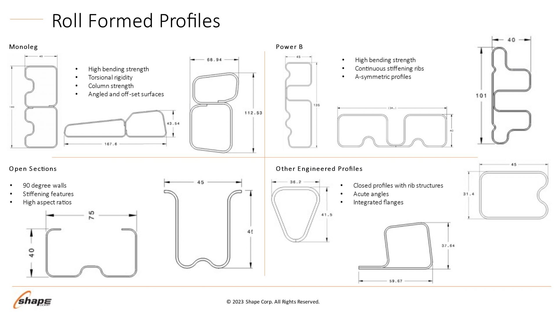
Figure 8: Roll forming profile design possibilities. Courtesy of Shape Corporation.
In summary, roll forming can produce AHSS parts with steels of all levels of mechanical properties and different microstructures with a reduced R/T ratio versus conventional bending. All deformation occurs at a radius, so there is no sidewall curl risk and overbending works to control angular springback.
Many thanks to Brian Oxley, Product Manager, Shape Corporation, and Dr. Daniel Schaeffler, President, Engineering Quality Solutions, Inc., for providing this case study.
Optimizing the use of roll forming requires understanding how the sheet metal behaves through the process.
Making a bend in a roll formed part occurs only when forming forces exceed the metal’s yield strength, causing plastic
deformation to occur. Higher strength sheet metals increase forming force requirements, leading to the need to have
larger shaft diameters in the roll forming mill. Each pass must have greater overbend to compensate for the increasing
springback associated with the higher strength.
Figure 9 provides a comparison of the loads on each pass of a 10-station roll forming line when forming either AISI 1020
steel (yield strength of 350 MPa, tensile strength of 450 MPa, elongation to fracture of 15%) or CR1220Y1500T-MS, a
martensitic steel with 1220 MPa minimum yield strength and 1500 MPa minimum tensile strength.
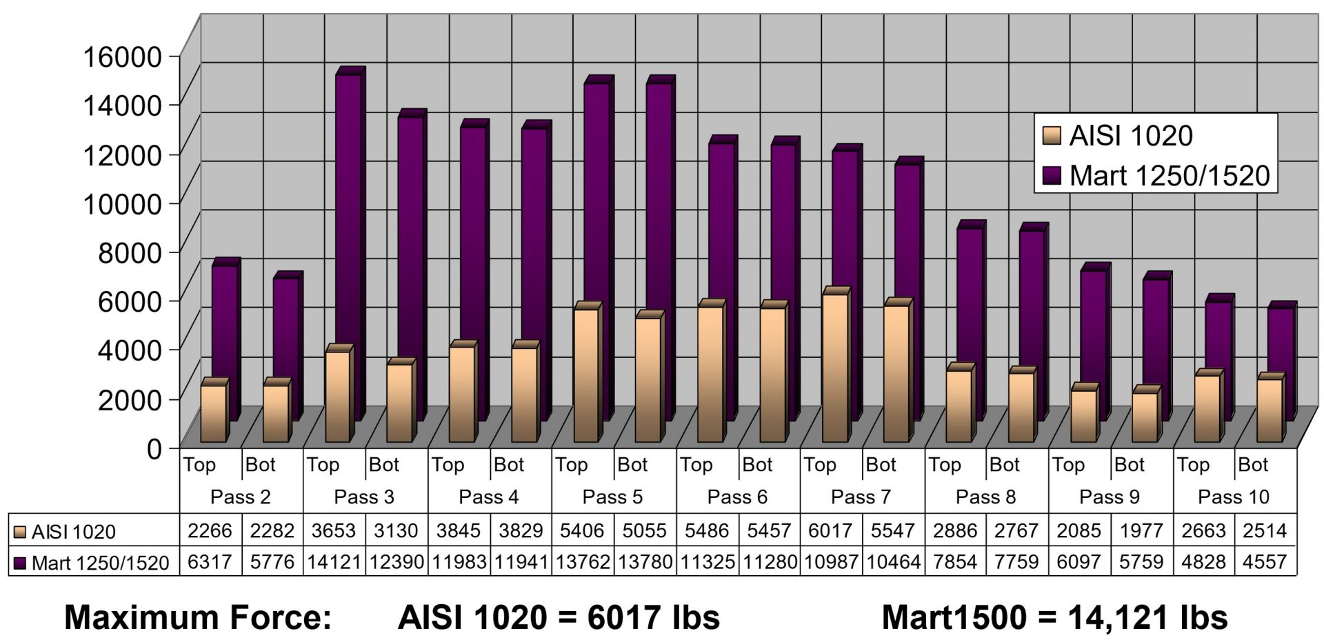
Figure 9: Loads on each pass of a roll forming line when forming either AISI 1020 steel (450 MPa tensile
strength) or a martensitic steel with 1500 MPa minimum tensile strength. Courtesy of Roll-Kraft.
Although a high-strength material requires greater forming loads, grades with higher yield strength can resist stretching
of the strip edge and prevent longitudinal deformations such as twisting or bow. Flange edge flatness after forming
either AISI 1020 or CR1220Y1500T-MS is presented in Figure 10.
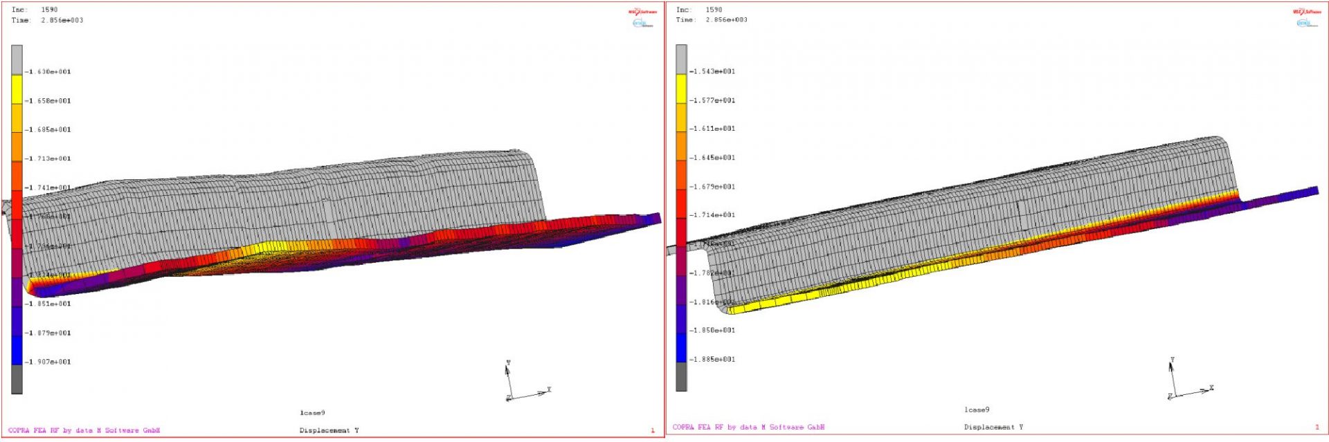
Figure 10: Simulation results showing flange edge flatness of a) AISI 1020 and b) CR1220Y1500T-MS.
Assumptions for the simulation: AISI 1020 yield strength = 350 MPa; CR1220Y1500T yield strength = 1220 MPa.
Higher yield strength leads to better flatness.
Force requirements for piercing operations are a function of the sheet tensile strength. High strains in the part design
exceeding uniform elongation resulting from loads in excess of the tensile strength produces local necking, representing
a structural weak point. However, assuming the design does not produce these high strains, the tensile strength has only
an indirect influence on the roll forming characteristics.
Yield strength and flow stress are the most critical steel characteristics for roll forming dimensional control. Receiving
metal with limited yield strength variability results in consistent part dimensions and stable locations for pre-pierced
features.
Flow stress represents the strength after some amount of deformation, and is therefore directly related to the degree of
work hardening: starting at the same yield strength, a higher work hardening steel will have a higher flow stress at the
same deformation.
Two grades are shown in Figure 11: ZE 550 and CR420Y780T-DP. ZE 550, represented by the red curve, is a recovery
annealed grade made by Bilstein having a yield strength range of 550 to 625 MPa and a minimum tensile strength of 600
MPa, while CR420Y780T-DP, represented by the blue curve, is a conventional dual phase steel with a minimum yield
strength of 420 MPa and a minimum tensile strength of 780 MPa. For the samples tested, ZE 550 has a yield strength of
approximately 565 MPa, where that for CR420Y780T-DP is much lower at about 485 MPa. Due to the higher work
hardening (n-value) of the DP steel, its flow stress at 5% strain is 775 MPa, while the flow stress for the HSLA grade at 5%
strain is 620 MPa.
In conventional stamping operations, this work hardening is beneficial to delay the onset of necking. However, use of
dual-phase steels and other grades with high n-value can lead to dimensional issues in roll-formed parts. Flow stress in a
given area is a function of the local strain. Each roll station induces additional strain on the overall part, and strains vary
within the part and along the edge. This strength variation is responsible for differing springback and edge wave across
a roll-formed part.
Unlike conventional stamping, grades with a high yield/tensile ratio where the yield strength is close to the tensile
strength are better suited to produce straight parts via roll forming.
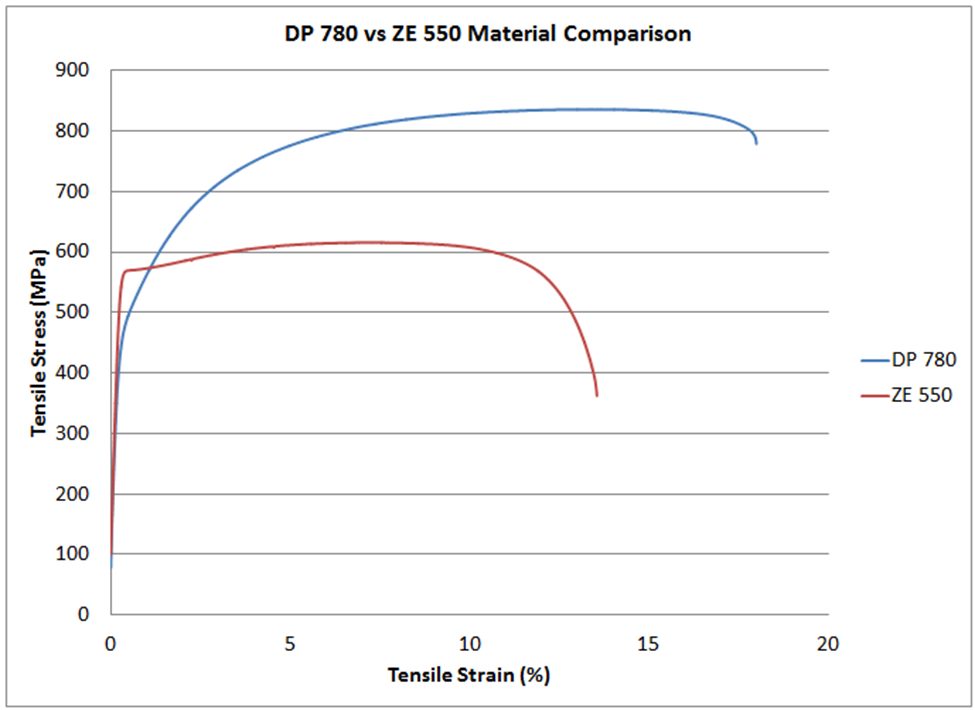
Figure 11: Stress-strain curves for CR420Y780T-DP (blue) and ZE 550 (red). See text for description of the grades.
Total elongation to fracture is the strain at which the steel breaks during tensile testing, and is a value commonly
reported on certified metal property documents (cert sheets). As observed on the colloquially called “banana diagram”,
elongation generally decreases as the strength of the steel increases.
For lower strength steels, total elongation is a good indicator for a metal’s bendability. Bend severity is described by the
r/t ratio, or the ratio of the inner bend radius to the sheet thickness. The metal’s ability to withstand a given bend can be
approximated by the tensile test elongation, since during a bend, the outermost fibers elongate like a tensile test.
In higher strength steels where the phase balance between martensite, bainite, austenite, and ferrite play a much larger
role in developing the strength and ductility than in other steels, bendability is usually limited by microstructural
uniformity. Dual phase steels, for example, have excellent uniform elongation and resistance to necking coming from
the hardness difference between ferrite and martensite. However, this large hardness difference is also responsible for
relatively poor edge stretchability and bendability. In roll forming applications, those grades with a uniform
microstructure will typically have superior performance. As an example, refer to Figure 11. The dual phase steel shown
in blue can be bent to a 2T radius before cracking, but the recovery annealed ZE 550 grade with noticeably higher yield
strength and lower elongation can be bent to a ½T radius.
Remember that each roll forming station only incrementally deforms the sheet, with subsequent stations working on a
different region. Roll formed parts do not need to use grades associated with high total elongation, especially since
these typically have a bigger gap between yield and tensile strength.
Along with the mechanical properties of steel, physical shape attributes of the sheet or coil can influence the roll
forming process. These include center buckle, coil set, cross bow, and camber. Receiving coils with these imperfections
may result in substandard roll formed parts.
Flatness is paramount when it comes to getting good shape on roll formed parts. Individual OEMs or processors may
have company-specific procedures and requirements, while organizations like ASTM offer similar information in the
public domain. ASTM A1030/A1030M is one standard covering the practices for measuring flatness, and specification
ASTM A568/A568M shows methods for characterizing longitudinal waves, buckles, and camber.
Center buckle (Figure 12), also known as full center, is the term to describe pockets or waves in the center or quarter
line of the strip. The height of pocket varies from 1/6” to 3/4”. Center buckle occurs when the central width portion of
the master coil is longer than the edges. This over-rolling of the center portion might occur when there is excessive
crown in the work roll, build-up from the hot strip mill, a mismatched set of work rolls, improper use of the benders, or
improper rolling procedures. A related issue is edge buckle presenting as wavy edges, originating when the coil edges
are longer than the central width position.
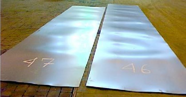
Figure 12: Coil shape imperfection: Center Buckle
Coil set (Figure 13a), also known as longitudinal bow, occurs when the top surface of the strip is stretched more than the
bottom surface, causing a bow condition parallel with the rolling direction. Here, the strip exhibits a tendency to curl
rather than laying flat. To some extent, coil set is normal, and easy to address with a leveler. Severe coil set may be
induced by an imbalance in the stresses induced during rolling by the thickness reduction work rolls. Potential causes include different diameters or surface speeds of the two work rolls, or different frictional conditions along the two arcs
of contact.
Crossbow (Figure 13b) is a bow condition perpendicular to the rolling direction, and arcs downward from the high point
in the center position across the width of the sheet. Crossbow may occur if improper coil set correction practices are
employed.
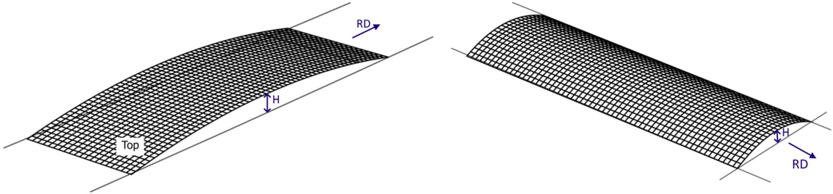
Figure 13: Coil shape imperfections: A) Coil set and B) Crossbow A-30
Camber (Figure 14) is the deviation of a side edge from a straight edge, and results when one edge of the steel is
elongated more than the other during the rolling process due to a difference in roll diameter or speed. The maximum
allowable camber under certain conditions is contained within specification ASTM A568/A568M, among others.

Figure 14: Coil shape imperfection: Camber
Coil shape imperfections produce residual stresses in the starting material. These residual stresses combined with the
stresses from forming lead to longitudinal deviations from targeted dimensions after roll forming. Some of the resultant
shapes of roll formed components made from coils having these issues are shown in Figure 15. Leveling the coil prior to
roll forming may address some of these shape concerns, and has the benefit of increasing the yield strength, making a
more uniform product.

Figure 15: Shape deviations in roll formed components initiating from incoming coil shape issues:
a) camber b) longitudinal bow c) twist d) flare e) center wave (center buckle) f) edge wave. H-66
Roll Stamping
Traditional roll forming creates products with essentially uniform cross sections. A newer technique called Roll Stamping enhances the ability to create shapes and features which are not in the rolling axis.
Using a patented processA-48, R-9, forming rolls with the part shape along the circumferential direction creates the desired form, as shown in Figure 16.
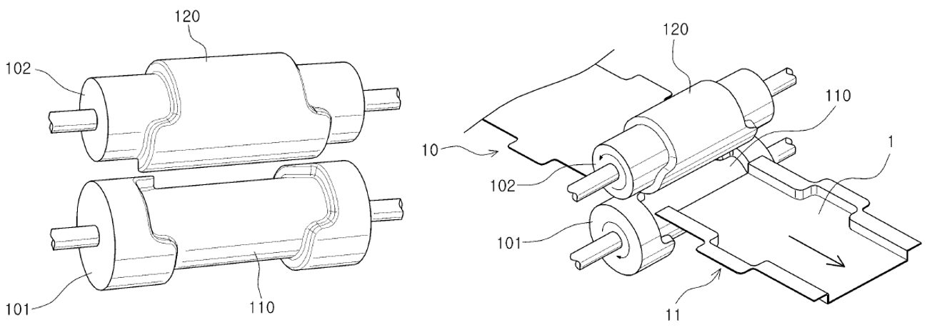
Figure 16: Roll Stamping creates additional shapes and features beyond capabilities of traditional roll forming. A-48
This approach can be applied to a conventional roll forming line. In the example of an automotive door impact beam, the W-shaped profile in the central section and the flat section which attaches to the door inner panel are formed at the same time, without the need for brackets or internal spot welds (Figure 17). Sharp corner curvatures are possible due to the incremental bending deformation inherent in the process.
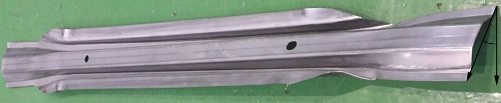
Figure 17: A roll stamped door part formed on a conventional roll forming line eliminates the need for welding brackets at the edges.R-9
A global automaker used this method to replace a three-piece door impact beam made with a 2.0 mm PHS-CR1500T-MB press hardened steel tube requiring 2 end brackets formed from 1.4 mm CR-500Y780T-DP to attach it to the door frame, shown in Figure 18. The new approach, with a one-piece roll stamped 1.0 mm CR900Y1180T-CP complex phase steel impact beam, resulted in a 10% weight savings and 20% cost savings.K-58 This technique started in mass production on a Korean sedan in 2017, a Korean SUV in 2020, and a European SUV in 2021.K-58
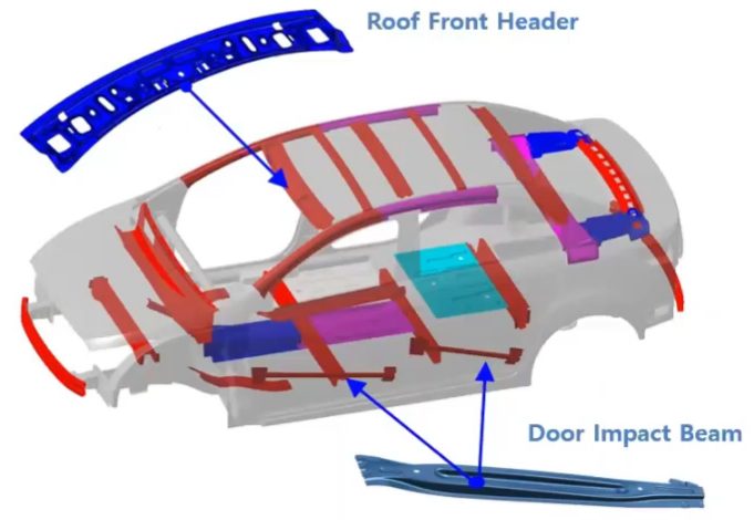
Figure 18: Some Roll Stamping Automotive Applications.K-58
 Thanks are given to Brian Oxley, Product Manager, Shape Corporation, for his contributions to the Roll Forming Case Study and Coil Shape Imperfections section. Brian Oxley is a Product Manager in the Core Engineering team at Shape Corp. Shape Corp. is a global, full-service supplier of lightweight steel, aluminum, plastic, composite and hybrid engineered solutions for the automotive industry. Brian leads a team responsible for developing next generation products and materials in the upper body and closures space that complement Shape’s core competency in roll forming. Brian has a Bachelor of Science degree in Material Science and Engineering from Michigan State University.

 Thanks go to Eren Billur, Ph.D. for his contribution of this article to the AHSS Insights blog. Eren Billur is the Technical Manager of Billur Makine and Billur Metal Form, based in Ankara, Turkey, specializing in advanced sheet metal forming technologies. He holds a Ph.D. in Mechanical Engineering from The Ohio State University and has extensive experience in material characterization, sheet metal forming processes, and finite element simulations. Eren has contributed significantly to the understanding and application of hot stamping and advanced high-strength steels (AHSS) in the automotive industry. He is a regular columnist for MetalForming Magazine’s “Cutting Edge” column and has authored numerous scientific papers and book chapters, including contributions to the WorldAutoSteel AHSS Applications Guidelines. Passionate about advancing manufacturing knowledge, Eren provides engineering consulting, training, and simulation services worldwide, helping manufacturers optimize forming processes and successfully implement new-generation AHSS materials.


