Blog, homepage-featured-top, main-blog
Efficient energy and resource use in automotive engineering is a major challenge that can only be overcome with innovative solutions. A cost-effective and resource-saving approach is the use of digital methods in production.
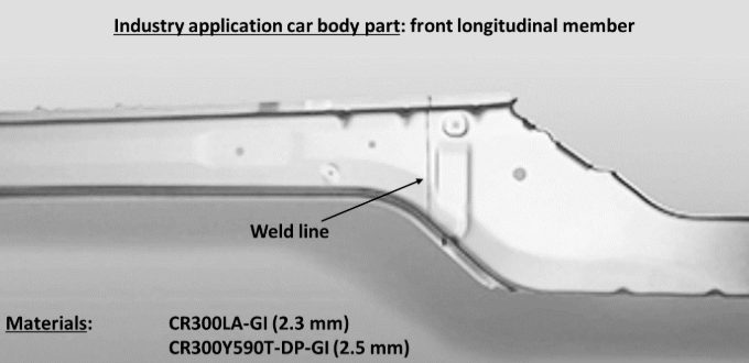
In demanding production chains like body-in-white components from tailor-welded blanks (TWBs), it is crucial to digitally simulate the product before actual production to prevent tool adjustments and unnecessary trials. A new digital twin for the tailor welded blanking process chain links numerical simulations for welding and forming steps. Figure 1 shows a typical application for a tailor welded blank component in the body in white: front longitudinal member.
Figure 1: A typical application for TWBs in the automotive industry is the longitudinal member shown here at the front. The TWB shown consists of micro-alloyed CR300 LA (2.3 mm) and high-strength dual phase steel with 600 MPa (2.5 mm). The welded sheet metal blanks were deep-drawn into the final shape of the TWB.
The process chain of laser beam welding and deep drawing faces challenges when pushing to stronger advanced high-strength steels. Areas around the weld seam are susceptible to softening due to heat input during welding, leading to changes in material properties, such as decreased strength in the heat-affected zone (HAZ) and hardening of the weld metal, influencing forming limit behavior.
Adapted welding process control can optimize material properties, ensuring laser beam welding’s applicability for AHSS grades. Consistent digital simulation of manufacturing processes is one of the most promising approaches for enabling low-emission, lightweight construction and maximizing material efficiency. To replace material-intensive experiments, simulations using the finite element analysis (FEA) create a virtual 3D model of a component.
Welding structure simulation validation is performed using thermocouple measurements and metallographic sections. The core of the forming simulation consists of material cards for high-strength steels. Yield curves, stress-strain curves, and forming limit diagrams are incorporated into the simulation. Validation experiments complete the forming simulation setup, comparing the deep-drawing press force-displacement curve with the modeled curve. The deep-drawn component is then digitized using a 3D scanner, allowing comparison of the real component with the simulated one in terms of geometry, defects, and sheet thickness. Figure 2 shows a simulated S-rail as demonstrator component after deep-drawing simulation.
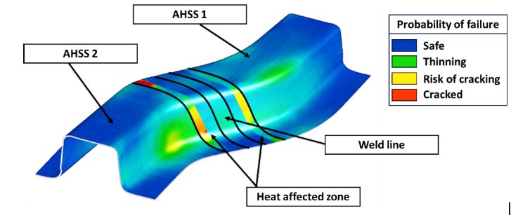
Figure 2: Simulation result of an S-rail formed from TWBs for the probability of failure (max. failure). Both the weld seam and the heat-affected zone are greatly oversized in the illustration for better visibility. The base materials are two high-strength steels of different sheet thicknesses, which were welded together using a butt joint. The heat-affected zone is represented as two areas with different properties.
Today’s forming simulation tools cannot readily account for the small geometric areas of weld metal and heat affected zones, hence the welding simulation results cannot be directly used as input for another software. In addition, it is difficult to measure material behavior of the welding zones to correctly model them in forming simulations. New interfaces were developed for a digital data management platform to bridge this gap. Intermediate steps are required to transfer welding results to forming simulation, including determining the heat-affected zone and deriving weld seam geometry. The analysis chain of the digital twin involves extracting welding simulation results, creating input for forming simulation and adjusting welding simulations based on forming results in an iterative loop. Figure 3 illustrates the digital process chain.
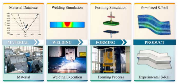
Figure 3: Scheme of the digital (top) and conventional (bottom) process chain of tailor welded blanking: main process steps from material to final product.
Linking welding and forming simulations (Figure 4) enable TWBs made of advanced high-strength steels reach higher strength levels, ultimately saving resources in car body construction and making production more sustainable. The development of TWBs for automotive construction serves as a starting point for expanding lightweight construction potential across the transport sector.
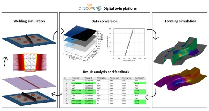
Figure 4: Bidirectional digital twin: How adapting welding simulation closes the loop. The welding simulation displays its results using three-dimensional volume elements. With the help of the digital platform, a simplified two-dimensional representation is generated that contains information about the position of the weld seam and heat-affected zone, which can then be modelled in shell elements. This data is used for the forming simulation and the result is fed back into the digital platform. The parameters of the best simulation results are highlighted and assist in the planning of new welding simulations.

A special thank you to our author, Josefine Lemke, M. Sc. She is a research associate at Fraunhofer IPK in Berlin, Department Joining and Coating Technology. She specialized in additive manufacturing and welding simulation. The focus is on the correlation of component quality and powder properties, particularly in the context of industry and SME environments. She is also working on the qualification of ultra-high-strength steels in car body construction (integration of laser welding and forming simulation in tailor-welded blanking).
Blog, homepage-featured-top, Joining, Joining Dissimilar Materials, main-blog, News, Resistance Spot Welding, Resistance Welding Processes, RSW Modelling and Performance, RSW of Dissimilar Steel
This blog is a short summary of a published comprehensive research work titled: “Peculiar Roles of Nickel Diffusion in Intermetallic Compound Formation at the Dissimilar Metal Interface of Magnesium to Steel Spot Welds” Authored by Luke Walker, Carolin Fink, Colleen Hilla, Ying Lu, and Wei Zhang; Department of Materials Science and Engineering, The Ohio State University
*****
There is an increased need to join magnesium alloys to high-strength steels to create multi-material lightweight body structures for fuel-efficient vehicles. Lightweight vehicle structures are essential for not only improving the fuel economy of internal combustion engine automobiles but also increasing the driving range of electric vehicles by offsetting the weight of power systems like batteries.
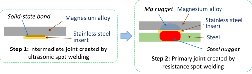
To create these structures, lightweight metals, such as magnesium (Mg) alloys, have been incorporated into vehicle designs where they are joined to high strength steels. It is desirable to produce a metallurgical bond between Mg alloys and steels using welding. However, many dissimilar metal joints form intermetallic compounds (IMCs) that are detrimental to joint ductility and strength. Ultrasonic interlayered resistance spot welding (Ulti-RSW) is a newly developed process that has been used to create strong dissimilar joints between aluminum alloys and high-strength steels. It is a two-step process where the light metal (e.g., Al or Mg alloy) is first welded to an interlayer (or insert) material by ultrasonic spot welding (USW). Ultrasonic vibration removes surface oxides and other contaminates, producing metal-to-metal contact and, consequently, a metallurgical bond between the dissimilar metals. In the second step, the insert side of the light metal is welded to steel by the standard resistance spot welding (RSW) process.
Cross-section View Schematics of Ulti-RSW Process Development
For resistance spot welding of interlayered Mg to steel, the initial schedule attempted was a simple single pulse weld schedule that was based on what was used in our previous study for Ulti-RSW of aluminum alloy to steel . However, this single pulse weld schedule was unable to create a weld between the steel sheet and the insert when joining to Mg. Two alternative schedules were then attempted; both were aimed at increasing the heat generation at the steel-insert interface. The first alternative schedule utilized two current pulses with Pulse 1, high current displacing surface coating and oxides and Pulse 2 growing the nugget. The other pulsation schedule had two equal current pulses in terms of current and welding time.
Lap shear tensile testing was used to evaluate the joint strength using the stack-up schematically, shown below. Note the images of Mg and steel sides of a weld produced by Ulti-RSW.
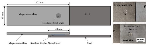 Lap Shear Tensile Test Geometry and the Resultant Weld Nuggets
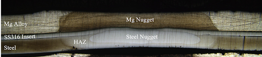
An example of a welded sample showed a distinct feature of the weld that is comprised of two nuggets separated by the insert: the steel nugget formed from the melting of steel and insert and the Mg nugget brazed onto the unmelted insert. This feature is the same as that of the Al-steel weld produced by Ulti-RSW in our previous work. Although the steel nugget has a smaller diameter than the Mg nugget, it is stronger than the latter, so the failure occurred on the Mg sheet side.
Joint strength depends on several factors, including base metal strength, sheet thickness, and nugget size, making it difficult to compare how strong a weld truly is from one process to another. To better compare the dissimilar joints created by different processes, joint efficiency, a “normalized” quantity was calculated for various processes used for dissimilar joining of Mg alloys to steels in the literature, and those results, along with the efficiencies of Ulti-RSW with inserts, are shown together below. Most of the literature studies also used AZ31 as the magnesium base metal. The ones with high joint efficiency (about 53%) in the literature are resistance element welding (REW) and friction stir spot welding (FSSW). In our study, Ulti-RSW with SS316 insert was able to reach an excellent joint efficiency of 71.3%, almost 20% higher than other processes.
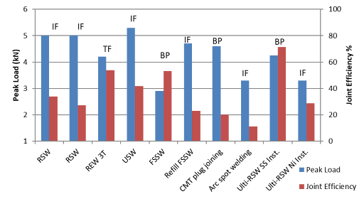 Process Evaluation and Comparison

Thanks are given to Menachem Kimchi, Associate Professor-Practice, Dept of Materials Science, Ohio State University, and Technical Editor – Joining, AHSS Application Guidelines, for this article.
Blog, homepage-featured-top, main-blog
 The leading source for technical best practices on the forming and joining of Advanced High-Strength Steels (AHSS) for vehicle manufacture is released today by WorldAutoSteel, the automotive group of the World Steel Association. The AHSS Application Guidelines Version 7.0 is now online at ahssinsights.org in a searchable database, allowing users to pinpoint information critical to successful use of these amazingly capable steels. WorldAutoSteel members make these Guidelines freely available for use to the world’s automotive community.
“More and more automakers are turning to AHSS to balance the needs for crashworthiness, lighter weight and lower emissions, while still manufacturing cars that are affordable,” says George Coates, Technical Director, WorldAutoSteel. “The AHSS Application Guidelines provides critical knowledge that will help users adapt their manufacturing environment to these evolving steels and understand processes and technologies that lead to efficient vehicle structures.” AHSS constitute as much as 70 percent of the steel content in vehicle structures today, according to automaker reports.
New grades of steel that are profiled in Version 7.0 show dramatically increased strength while achieving breakthrough formability, enabling applications and geometries that previously were not attainable.
“Steel’s low primary production emissions, now coupled with efficient fabrication methods, as well as a strong global recycling and reuse infrastructure all create a solid foundation upon which to pursue vehicle carbon neutrality,” notes Cees ten Broek, Director, WorldAutoSteel. “These Guidelines contain knowledge gleaned from global research and experience, including significant investment of our members who are the designers and manufacturers of these steels.”
Editors and Authors Dr. Daniel Schaeffler, President Engineering Quality Solutions, Inc., for Metallurgy and Forming, and Menachem Kimchi, M.Sc., Assistant Professor – Practice, Materials Science and Engineering, Ohio State University, have drawn from the insights of WorldAutoSteel members companies, automotive OEMs and suppliers, and leading steel researchers and application experts. Together with their own research and field experience, the technical team have refreshed existing data and added a wealth of new information in this updated version.
The new database includes a host of new resources for automotive engineers, design and manufacturing personnel and students of automotive manufacturing, including:
- Hundreds of pages of searchable articles that include nearly 1,000 citations of original technical research papers, providing a rich library for study.
- Search tools and related posts fueled by thousands of industry-specific keywords that enable users to drill down to the information they need.
- Information on the metallurgy and mechanics of AHSS grades.
- An explanation of 3rd Gen AHSS and what makes these grades unique.
- A primer on Press Hardened Steels, one of the most popular AHSS grades in today’s automotive structures.
- Summaries of new research in resistance spot welding for joining AHSS of multiple grades and thicknesses.
- New information on modelling resistance spot welding.
- An expanded solid state welding section.
- New information on RSW joining of dissimilar steels as well as dissimilar materials.
- Articles written by subject-matter experts and product manufacturers.
- Integration of the popular AHSS Insights technical blog.
The new online format enables consistent annual updates as new mastery of AHSS’s unique microstructures is gained, new technology and grades are developed, and data is gathered. Be sure to subscribe to receive regular updates and blogs that represent a world of experience as the database evolves.
You’re right where you need to be to start exploring the database. Click Tutorials from the top menu to get a tour on how the site works so you can make the best of your experience. Come back often–we’re available 24/7 anywhere in the world, no download needed!
RSW of Dissimilar Steel
This article is the summary of a paper entitled, “HAZ Softening of RSW of 3T Dissimilar Steel Stack-up”, Y. Lu., et al.L-15
Electromechanical Model
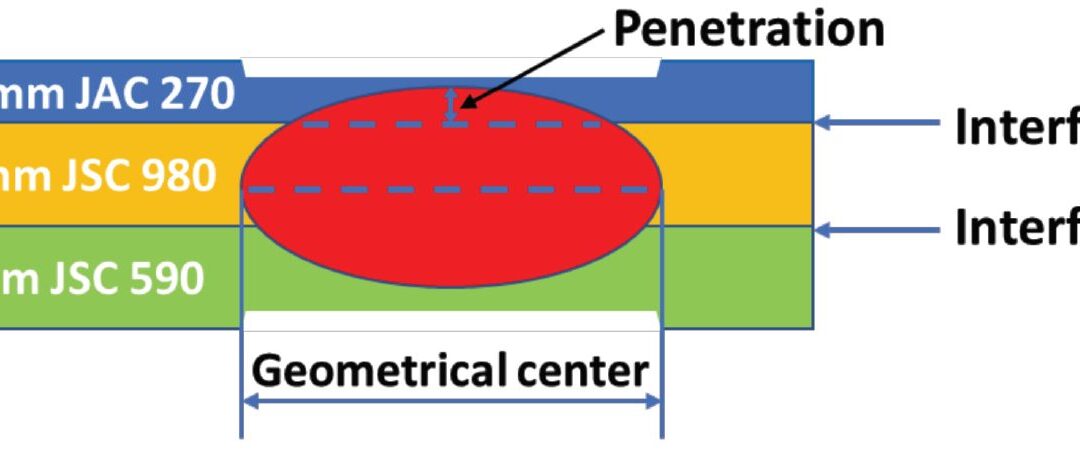
The study discusses the development of a 3D fully coupled thermo-electromechanical model for RSW of a three sheet (3T) stack-up of dissimilar steels. Figure 1 schematically shows the stack-up used in the study. The stack-up chosen is representative of the complex stack-ups used in BIW. Table 1 summarizes the nominal compositions of the three steels labeled in Figure 1.
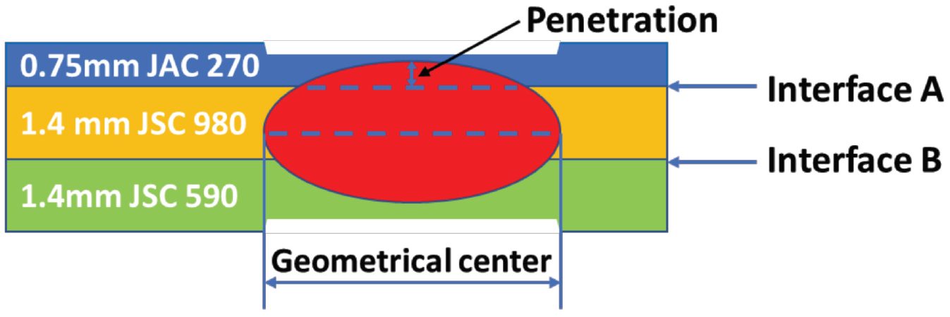
Figure 1: Schematics of the 3T stack-up of 0.75-mm-thick JAC 270/1.4-mm-thick JSC 980/1.4-mm-thick JSC 590 steels.L-15
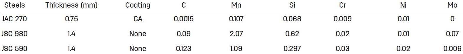
Table 1: Nominal Composition of Steels.L-15
JAC270 is a cold rolled Mild steel with a galvanneal coating having a minimum tensile strength of 270 MPa. JSC590 and JSC980 are bare cold rolled Dual Phase steels with a minimum tensile strength of 590 MPa and 980 MPa, respectively.
The electrodes used were CuZr dome-radius electrodes with a surface diameter of 6 mm. The welding parameters are listed in Table 2.
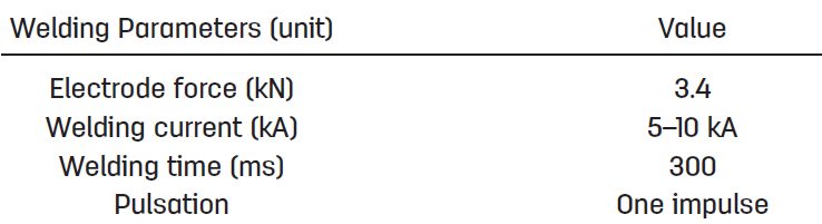
Table 2: Welding Parameters for Resistance Spot Welding of 3T Stack-Up of Steel Sheets.L-15
Figure 2 shows consistent nugget dimensions between simulation and experiment, supporting the validity of the RSW process model for 3T stack-up. The effect of welding current on nugget penetration into the thin sheet is similar to that on the nugget size. It increases rapidly at low welding current and saturates to 32% when the welding current is higher than 9 kA, as shown in Figure 2C.
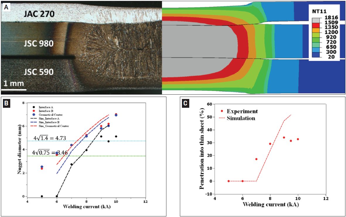
Figure 2: Comparison between experimental and simulated results: A) Nugget geometry at 8 kA; B) nugget diameters; C) nugget penetration into the thin sheet as a function of welding current. In Figure 2A, the simulated nugget geometry is represented by the distribution of peak temperature (in Celsius). The two horizontal lines in Figure 2B represent the minimal nugget diameter at Interfaces A and B calculated, according to AWS D8.1M: 2007, Specification for Automotive Weld Quality Resistance Spot Welding of Steel. Due to limited number of samples available for testing, the variability in nugget dimensions at each welding current was not measuredL-15.
The results for nugget formation during RSW of the 3T stack-up are show in Figures 3-5. Figure 2 shows that, at the start of welding, the contact pressure at interface A (thin/thick) has a higher peak and drops more quickly along the radial direction than that at interface B (thick/thick). Due to the more localized contact area (Figure 3), a high current density can be observed at interface A, as shown in Figure 4A. Additionally, due to the high current density at interface A, localized heating is generated at this interface, as shown in Figure 5A.
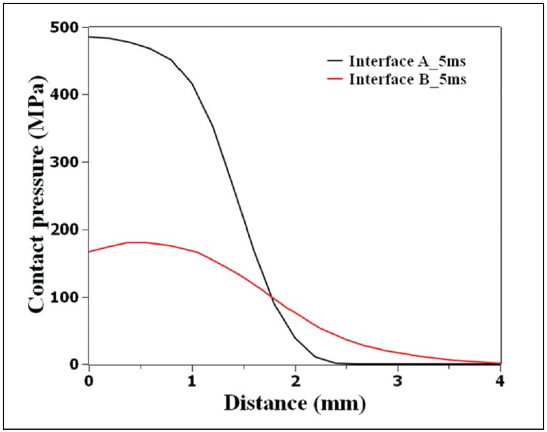
Figure 3: Calculated contact pressure distribution at interfaces A (thin/thick) and B (thick/thick) at a welding time of 5 ms, current of 8 kA, and electrode force of 3.4 L-15
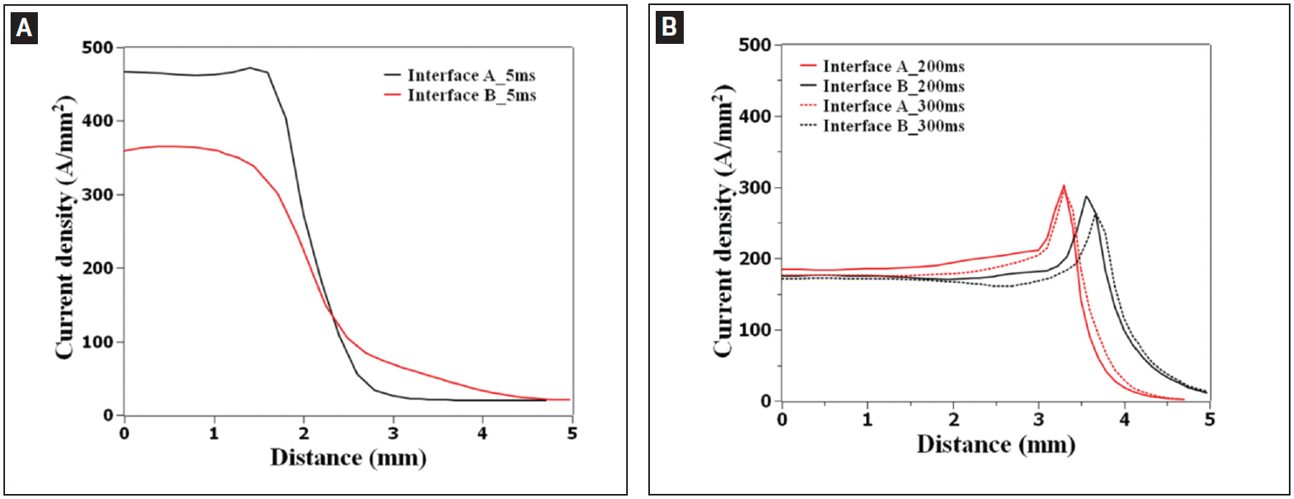
Figure 4: Calculated current density distribution at interfaces A (thin/thick) and B (thick/thick) at welding time of A — 5 ms; B — 200 and 300 ms.L-15
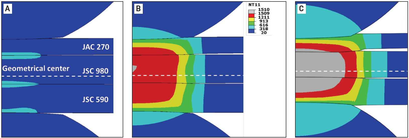
Figure 5: Temperature distribution during resistance spot welding of 3T stack-up at welding times of A) 5 ms; B) 102 ms; C) 300 ms. Welding current is 8 kA and electrode force is 3.4 kN. Calculated temperature is given in Celsius.L-15
As welding time increases, the contact area is expanded, resulting in a decrease of current density. The heat generation rate is shifted from interfaces to the bulk and the peak temperature occurs near the geometrical center of the stack-up.
Figure 6 illustrates that the predicted value corresponds well with the experimental data indicating a sound fitting to the isothermal tempering experimental data.
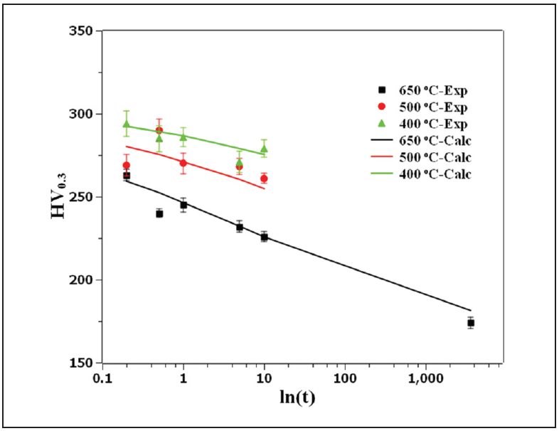
Figure 6: Comparison of the measured hardness with JMAK calculation showing the goodness of fit of the JSC 980 tempering kinetics parameters.L-15
Figure 7 shows the predicted hardness map of RSW 3T stack-up as well as the predicted and measured hardness profiles for JSC 980.
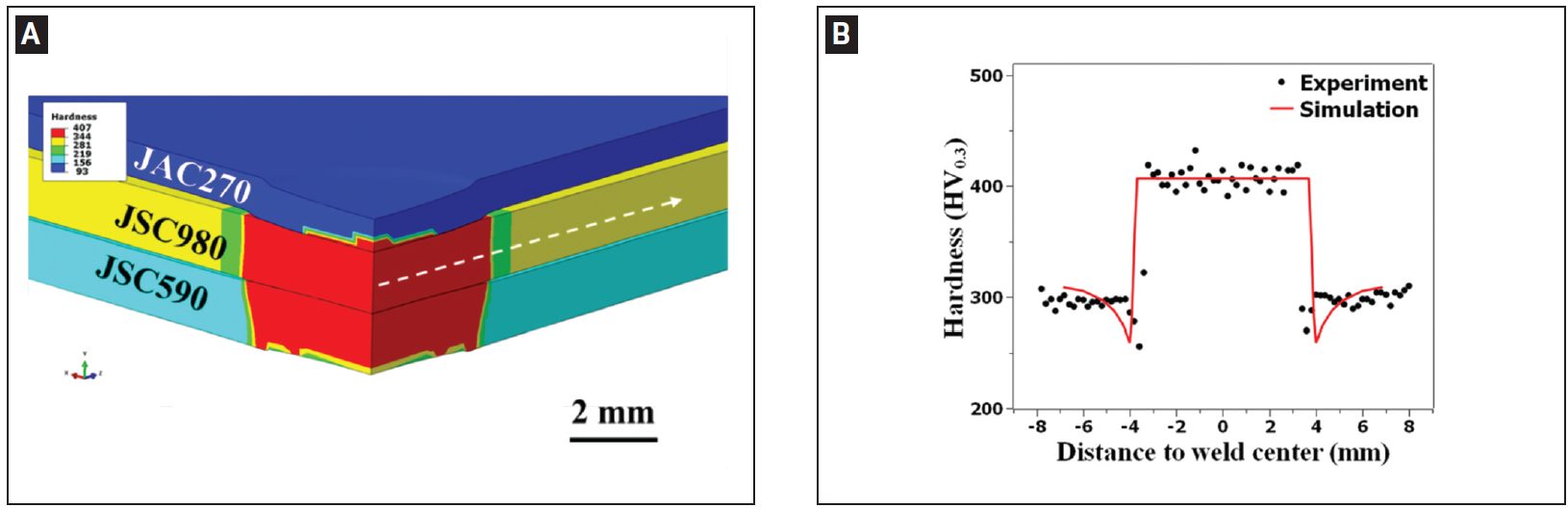
Figure 7: A) Predicted hardness map of resistance spot welded 3T stack-up; B) predicted and measured hardness profiles along the line marked in (A) for JSC 980.L-15
Blog, RSW Joint Performance Testing
top-of-page
Results of a Three-Year LME Study
WorldAutoSteel releases today the results of a three-year study on Liquid Metal Embrittlement (LME), a type of cracking that is reported to occur in the welding of Advanced High-Strength Steels (AHSS).The study results add important knowledge and data to understanding the mechanisms behind LME and thereby finding methods to control and establish parameters for preventing its occurrence. As well, the study investigated possible consequences of residual LME on part performance, as well as non-destructive methods for detecting and characterizing LME cracking, both in the laboratory and on the manufacturing line (Figure 1).
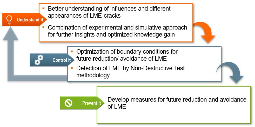
Figure 1: LME Study Scope
The study encompassed three different research fields, with an expert institute engaged for each:
- Laboratory of Materials and Joining Technology (LWF) Paderborn University, Paderborn, Germany, for experimental research,
- The Institute de Soudure, Yutz, France, for investigations regarding non-destructive testing, and
- Fraunhofer Institute for Production Systems and Design Technology (IPK), Berlin, Germany, for the development of a simulation model to accurately replicate welding conditions resulting in LME.
A portfolio containing 13 anonymized AHSS grades, including dual phase (DP), martensitic (MS) and retained austenite (RA) with an ultimate tensile strength (UTS) of 800 MPa and higher, was used to set up a testing matrix, which enabled the replication of the most relevant and critical material thickness combinations (MTC). All considered MTCs show a sufficient weldability under use of standard parameters according to SEP1220-2. Additional MTCs included the joining of various strengths and thicknesses of mild steels to select AHSS in the portfolio. Figure 2 provides the welding parameters used throughout the study.
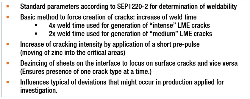
Figure 2: Study Welding Parameters
In parallel, a 3D electro-thermomechanical simulation model was set up to study LME. The model is based on temperature-dependent material data for dual phase AHSS as well as electrical and thermal contact resistance measurements and calculates local heating due to current flow as well as mechanical stresses and strains. It proved particularly useful in providing additional means to mathematically study the dynamics observed in the experimental tests. This model development was documented in two previous AHSS Insights blogs (see AHSS Insights Related Articles below).
Understanding LME
The study began by analyzing different influence factors (Figure 3) which resembled typical process deviations that might occur during car body production. The impact of the influences was analyzed by the degree of cracking observed for each factor. A select number of welding set-ups from these investigations were rebuilt digitally in the simulation model to replicate the process and study its dynamics mathematically. This further enabled the clarification of important cause-effect relationships.
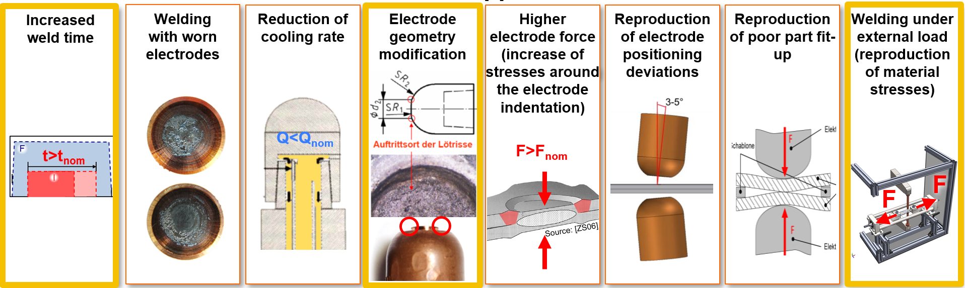
Figure 3: Overview of All Applied Influence Factors (those outlined in yellow resulted in most frequent cracking.)
Generally, the most frequent cracking was observed for sharp electrode geometries, increased weld times and application of external loads during welding. All three factors were closely analyzed by combining the experimental approach with the numerical approach using the simulation model.
Destructive Testing – LME Effects on Mechanical Joint Strength
A destructive testing program also was conducted for an evaluation of LME impact on mechanical joint strength and load bearing capacity in multiple conditions, including quasi-static loading, cyclic loading, crash tests and corrosion. In summary of all load cases, it can be concluded that LME cracks, which might be caused by typical process deviations (e.g. bad part fit up, worn electrodes) have a low intensity impact and do not affect the mechanical strength of the spot weld. And as previously mentioned, the study analyses showed that a complete avoidance of LME during resistance spot welding is possible by the application of measures for reducing the critical conditions from local strains and exposure to liquid zinc.
Controlling LME
In welding under external load experiments, the locations of the experimental crack occurrence showed close correlation with the strains and remaining plastic deformations computed by the simulation model. It was observed that the cracks form at the location of the highest plastic strains, and material-specific threshold values for critical strains were derived. The threshold values then were used to judge the crack formation at elongated weld times.
At the same time, the simulation model pointed out a significant difference in liquid zinc diffusion during elongated weld times. Therefore, it is concluded that liquid zinc exposure time is a second highly relevant factor for LME formation.
The results for the remaining influence factors depended on the investigated MTCs and were generally less significant. In more susceptible MTCs (AHSS welded with thick Mild steel), no significant cracking occurred when welded using standard process parameters. Light cracking was observed for most of the investigated influences, such as low electrode cooling rate, worn electrode caps, electrode positioning deviations or for gap afflicted spot welds. More intense cracking (higher penetration depth cracking) was only observed when welding under extremely high external loads (0.8 Re) or, even more, as a consequence of highly increased weld times.
For the non-susceptible MTCs, even extreme situations and weld set-ups (such as the described elongated weld times) did not result in significant LME cracks within the investigated AHSS grades.
Methods for avoidance of LME also were investigated. Changing the electrode tip geometry to larger working plane diameters and elongating the hold time proved to eliminate LME cracks. In the experiments, a change of electrode tip geometry from a 5.5 mm to an 8.0 mm (Figure 4) enabled LME-free welds even when doubling the weld times above 600 ms. Using a flat-headed cap (with small edge radii or beveled), even the most extreme welding schedules (weld times greater than 1000 ms) did not produce cracks. The in-depth analysis revealed that larger electrode tip geometries clearly reduce the local plastic deformation around the indentation. This plastic strain reduction is particularly important, as longer weld times contribute to a higher liquid zinc exposure interval, leading to a higher potential for LME cracks.
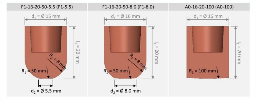
Figure 4: Electrode Geometries Used in Study Experiments
It was also seen that as more energy flows into a spot weld, it becomes more critical to parameterize an appropriate hold time. Depending on the scenario, the selection of the correct hold time alone can make the difference between cracked and crack-free welds. Insufficient hold times allow liquid zinc to remain on the steel surface and increased thermal stresses that form after the lift-off of the electrode caps. Elongated hold times reduce surface temperatures, minimizing surface stresses and thus LME potential.
Non-Destructive Testing: Laboratory and Production Capabilities
A third element of the study, and an aid in the control of LME, is the detection and characterization of LME cracks in resistance spot welds, either in laboratory or in production conditions. This work was done by the Institute of Soudure in close cooperation with LWF, IPK and WorldAutoSteel members’ and other manufacturing facilities. Ten different non-destructive techniques and systems were investigated. These techniques can be complementary, with various levels of costs, with some solutions more technically mature than others. Several techniques proved to be successful in crack detection. In order to aid the production source, techniques must not only detect but also characterize cracks to determine intensity and the effect on joint strength. Further work is required to achieve production-level characterization.
The study report provides detailed technical information concerning the experimental findings and performances of each technique/system and the possible application cost of each. Table 1 shows a summary of results:
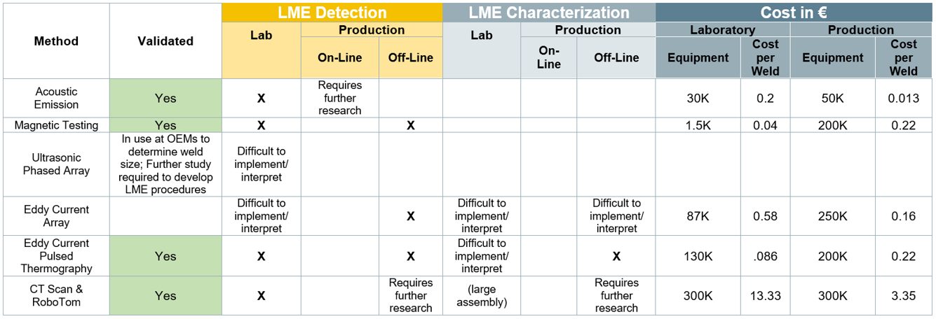
Table 1: Summary of NDT: LME Detection and Characterization Methods
Preventing LME
Suitable measures should always be adapted to the specific use case. Generally, the most effective measures for LME prevention or mitigation are:
- Avoidance of excessive heat input (e.g. excess welding time, current).
- Avoidance of sharp edges on spot welding electrodes; instead use electrodes with larger working plane diameter, while not increasing nugget-size.
- Employing extended hold times to allow for sufficient heat dissipation and lower surface temperatures.
- Avoidance of improper welding equipment (e.g. misalignments of the welding gun, highly worn electrodes, insufficient electrode cooling)
In conclusion, a key finding of this study is that LME cracks only occurred in the study experiments when there were deviations from proper welding parameters and set-up. Ensuring these preventive measures are diligently adhered to will greatly reduce or eliminate LME from the manufacturing line. For an in-depth review of the study and its findings, you can download a copy of the full report at worldautosteel.org.
LME Study Authors
The LME study authors were supported by a committed team of WorldAutoSteel member companies’ Joining experts, who provided valuable guidance and feedback.
Related Articles: More on this study in previous AHSS Insights blogs:
Journal Publications:
- Julian Frei, Max Biegler, Michael Rethmeier, Christoph Böhne & Gerson Meschut (2019) Investigation of liquid metal embrittlement of dual phase steel joints by electro-thermomechanical spot-welding simulation, Science and Technology of Welding and Joining, 24:7, 624-633, DOI: 10.1080/13621718.2019.1582203
- Christoph Böhne, Gerson Meschut, Max Biegler, Julian Frei & Michael Rethmeier (2020) Prevention of liquid metal embrittlement cracks in resistance spot welds by adaption of electrode geometry, Science and Technology of Welding and Joining, 25:4, 303-310, DOI: 10.1080/13621718.2019.1693731
-
Auto/Steel Partnership LME Testing and Procedures
Back To Top