AHSS, Blog, homepage-featured-top, main-blog, Mechanical Properties, News
Tensile testing is one of the most basic formability characterization methods available. Results from tensile testing are a key input into metal forming simulations, but if the right information isn’t included, the simulation will not accurately reflect material behavior.
Metal forming simulation is particularly beneficial on the value-added parts made from advanced high strength steels, since accurate simulations allow for optimal processing with minimal recuts … at least when the right information is used as inputs.
Tensile Testing
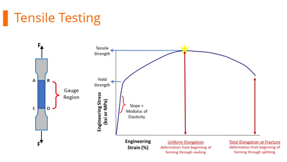
During tensile testing, a standard sample shape called a dogbone is pulled in tension. Load and displacement are recorded, and which are then converted to a stress-strain curve. Strength is defined as load divided by cross-sectional area. Exactly when the cross-sectional area is measured during the test influences the results.
Before starting the pull, it’s easiest to measure the width and thickness of the test sample.
Engineering Stress-Strain Curve
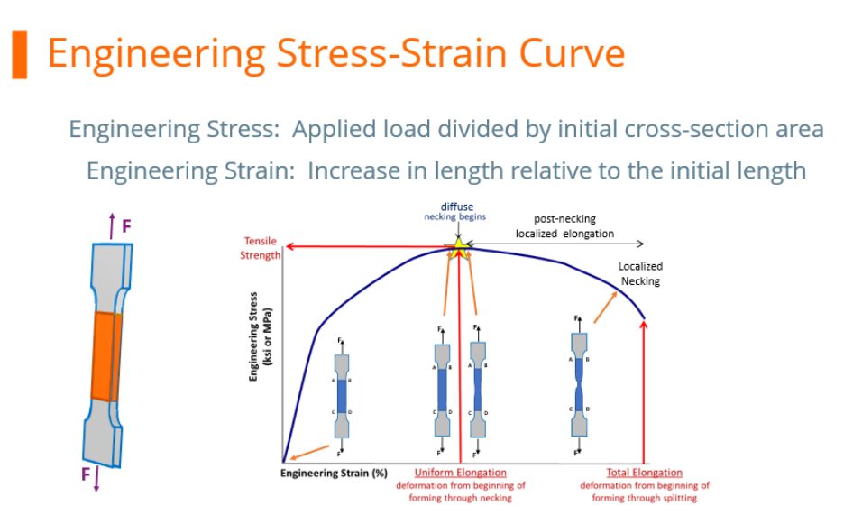
At any load, the engineering stress is the load divided by this initial cross-sectional area. Engineering stress reaches a maximum at the Tensile Strength, which occurs at an engineering strain equal to Uniform Elongation. After that point, engineering stress decreases with increasing strain, progressing until the sample fractures.
However, metals get stronger with deformation through a process known as strain hardening or work hardening. As a tensile test progresses, additional load must be applied to achieve further deformation, even after the “ultimate” tensile strength is reached. Understanding true stress and true strain helps to address the need for additional load after the peak strength is reached.

During the tensile test, the width and thickness shrink as the length of the test sample increases. Although these dimensional changes are not considered when determining the engineering stress, they are of primary importance when determining true stress. At any load, the true stress is the load divided by the cross-sectional area at that instant.
True Stress-Strain Curve
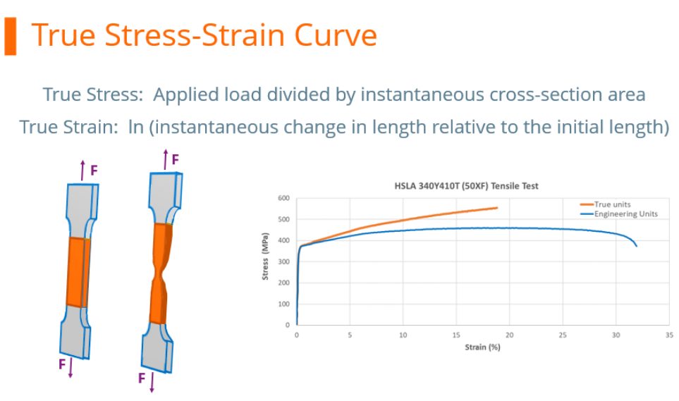
The true stress – true strain curve gives an accurate view of the stress-strain relationship, one where the stress is not dropping after exceeding the tensile strength stress level.
True stress is determined by dividing the tensile load by the instantaneous area.
True stress-strain curves obtained from tensile bars are valid only through uniform elongation due to the effects of necking and the associated strain state on the calculations. Inaccuracies are introduced if the true stress-true strain curve is extrapolated beyond uniform strain, and as such a different test is needed. Biaxial bulge testing has been used to determine stress-strain curves beyond uniform elongation. Optical measuring systems based on the principles of Digital Image Correlation (DIC) are used to measure strains. The method by which this test is performed is covered in ISO 16808.
Stress-strain curves and associated parameters historically were based on engineering units, since starting dimensions are easily measured and incorporated into the calculations. These are the values you see on certified metal properties, also called metal cert sheets that you get with your steel shipments.
True stress and true strain provide a much better representation of how the material behaves as it is being deformed, which explains its use in computer forming and crash simulations.
It’s much more challenging to get accurate dimensional measurements once the test has started unless there are multiple loops of the operator stopping the test, remeasuring, then restarting the pull. This is not a practical approach.
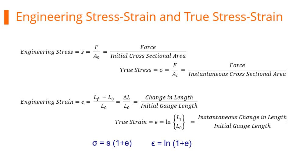
Fortunately, there are equations that relate engineering units to true units. Conventional stress-strain curves generated in engineering units can be converted to true units for inclusion in simulation software packages.
As the industry moves to more value-added stampings, metal forming simulation is done on nearly every part. The value-added nature of parts made from advanced high strength steels requires best practices be used throughout – otherwise the results from simulation drift further away from matching reality, leading to longer development times and costly recuts.

Danny Schaeffler is the Metallurgy and Forming Technical Editor of the AHSS Applications Guidelines available from WorldAutoSteel. He is founder and President of Engineering Quality Solutions (EQS). Danny wrote the monthly “Science of Forming” and “Metal Matters” column for Metalforming Magazine, and provides seminars on sheet metal formability for Auto/Steel Partnership and the Precision Metalforming Association. He has written for Stamping Journal and The Fabricator, and has lectured at FabTech. Danny is passionate about training new and experienced employees at manufacturing companies about how sheet metal properties impact their forming success.
AHSS, Blog, homepage-featured-top, Joining, Joining Dissimilar Materials, main-blog, Steel Grades
The discussions relative to cold stamping are applicable to any forming operation occurring at room temperature such as roll forming, hydroforming, or conventional stamping. Similarly, hot stamping refers to any set of operations using Press Hardening Steels (or Press Quenched Steels), including those that are roll formed or fluid formed.
Automakers contemplating whether a part is cold stamped or hot formed must consider numerous factors. This blog covers some important considerations related to welding these materials for automotive applications. Most important is the discussion on Resistance Spot Welding (RSW) as it is the dominating process in automotive manufacturing.
Setting Correct Welding Parameters for Resistance Spot Welding
Specific welding parameters need to be developed for each combination of material type and thickness. In general, the Hot Press (HP) steels require more demanding process conditions. One important factor is electrode force which should be higher for the HP steel than for cold press type steel of the same thickness. The actual recommended force will depend on the strength level, and the thickness of the steel. Of course, this will affect the welding machine/welding gun force capability requirement.
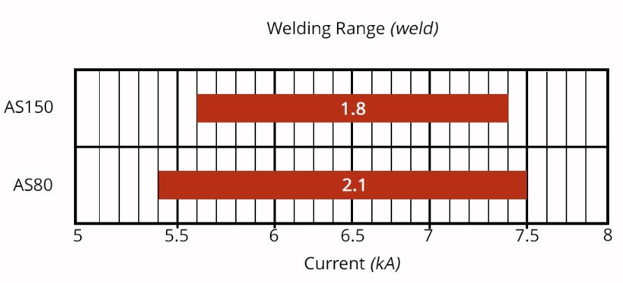
Another important variable is the welding current level and even more important is the current range at which acceptable welds can be made. The current range is weldability measurement, and the best indicator of the welding process robustness in the manufacturing environment and sometime called proceed window. Note the relative range of current for different steel types. A smaller process window may require more frequent weld quality evaluation such as for weld size.

Relative Current Range (process windows) for Different Steel Types
The Effect of Coating Type on Weldability
In all cases of resistance spot welding coated steels, it is imperative to move the coating away from the weld area during and in the beginning of the weld cycle to allow a steel-to-steel weld to occur. The combination of welding current, weld time and electrode force are responsible for this coating displacement.
For all the coated steels, the ability of the coating to flow is a function of the coating type and properties, such as electrical resistivity and melting point, as well as the coating thickness.
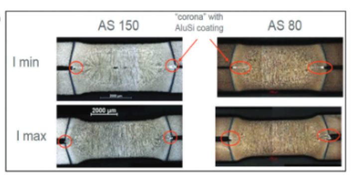
An example of cross sectioned spot welds made on Hot Press Steel with Aluminum -Silicon coating is shown below. It shows two coating thicknesses and the displaced coating at the periphery of weld. This figure also shows the difference in current range for the different coating thickness. The thicker coating shows a smaller current range. In addition, the Al-Si coating has a much higher melting point than the zinc coatings on the cold stamped steels, making it more difficult to displace from the weld area.

Hot Press Steel with Aluminum -Silicon
Liquid Metal Embrittlement and Resistance Spot Welding
Cold-formable, coated, Advance High Strength Steels such as the 3rd Generation Advanced High Strength Steels are being widely used in automotive applications. One welding issue these materials encounter is the increased hardness in the weld area, that sometime results in brittle fracture of the weld.
Another issue is their sensitivity to Liquid Metal Embrittlement (LME) cracking. These two issues are discussed in detail on the WorldAutoSteel AHSS Guidelines website and our recently released Phase 2 Report on LME.
Resistance Spot Welding Using Current Pulsation
The most effective solution for the issues described above is using current pulsation during the welding cycle. A schematic description is shown below.
The pulsation allows much better control of the heat generation and the weld nugget development. The pulsation variables include the number of pulses (typically 2-4), the current level and time for each pulse, and the cool time between the pulses.

In summery, pulsation (and sometime current upslope) in Resistance Spot Welding proved to be beneficial for the following applications:
- Coated Cold Stamped steels
- Cold stamped Advance High Strength Steels
- Multi materials stack-ups – As described in our articles here on 3T/4T and 5T Stack-Ups

Thanks is given to Menachem Kimchi, Associate Professor-Practice, Dept of Materials Science, Ohio State University and Technical Editor – Joining, AHSS Application Guidelines, for this article.
AHSS, Blog, homepage-featured-top, main-blog, News
High-volume automotive body structures using Advanced High-Strength Steel (AHSS) grades offer the potential for low cost and weight, high strength performance, and competitive life-cycle and sustainability attributes.
Reducing the number of individual parts within an automotive body structure can yield further cost, weight, and sustainability benefits without compromising performance.
WorldAutoSteel’s latest engineering demonstrator project, Steel E-Motive, delivered a clean-sheet body structure concept for a fully autonomous Mobility as a Service vehicle. The body structure design features components and sub-assemblies where the number of individual parts (i.e., stampings) have been reduced by applying fabrication methods such as hydroforming and tailor welded blanks, combined with the latest AHSS grades such as Press Hardened/Hot Formed and 3rd generation/Retained Austenite grades.
Integrating multiple body structure parts yields more efficient material utilization (reduced scrap), enabling cost & weight reduction, structural performance improvement, and life-cycle Greenhouse Gas (GHG) benefits.
Some examples of steel body structure part integration applied to the Steel E-Motive concept design follow:
Part Integration Through Hydroformed B and D Pillars
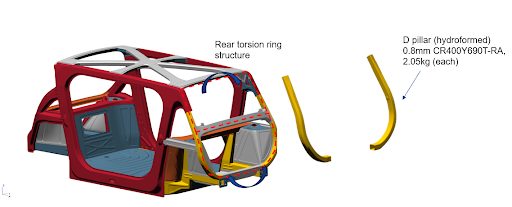
Tube hydroforming enables the creation of complex geometries by using internal pressure to expand a tube against a die cavity. The result is a single tubular component with no weld flanges, offering uniform properties with higher overall strength and stiffness than a component fabricated (i.e., welded) from multiple parts. Hydroformed parts have high material utilization rates (low scrap), giving good cost and weight efficiency. The Steel E-Motive body structure features hydroformed tubes for the B and D pillars.
Steel E-Motive B Pillars
The B pillar acts as one of the main structural members protecting the vehicle occupants and propulsion battery in the event of a high-speed side impact collision. Crash simulations demonstrate that the Steel E-Motive SEM1 vehicle has the potential to achieve IIHS “good” (highest) side crash rating, and the battery is well protected in the event of a collision. Steel E-Motive B pillars are positioned on the closing edges of the front and rear side closures. In the event of a high-speed side collision, the B pillar section profiles ensure that both B pillars deform, contact, and combine to produce an effective box section that reacts to the side impact crash loads, minimizing intrusion.
A compact and efficient section profile enables overlapping and interlocking features and maximizes the windows’ size, enhancing occupants’ visibility. Tube hydroforming enables the achievement of such complex geometric profiles. A TRIP690 (CR400Y690T-RA) grade AHSS was selected for the B pillars. Its high yield and UTS strength deliver side crash performance, and up to 25% elongation enables the complex geometry profiles to be achieved.
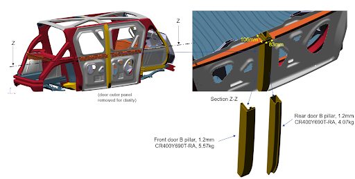
The hydroformed tube approach for the Steel E-Motive B pillars has enabled an integrated part solution, with a 10-15% cost and weight saving compared to a cold stamped and spot welded design.
Steel E-Motive D pillars
The Steel E-Motive D pillars are an integral part of the rear torsion ring structure, which significantly contributes to the static and NVH torsional stiffness of the BIW structure. The tube hydroformed D pillars effectively enable 2 to 3 cold stamped and spot-welded parts to be integrated into a flange-less single component, achieving higher overall stiffness, improved material utilization, and improved overall performance.

The hydroformed D pillars of the Steel E-Motive BIW are another example of part efficiency and integration, providing cost, weight, and performance benefits.
Find further details on tube hydroforming using steel: https://ahssinsights.org/forming/hydroforming/hydroforming/
The newest AHSS grades and fabrication techniques enable engineers to streamline automotive body structures by reducing the number of parts or blanks needed. The Steel E-Motive concept showcases several successful part consolidation processes, which lead to lower scrap rates, better material utilization, reduced costs, and decreased GHG emissions. Additionally, these integrated structures enhance overall stiffness and strength.

Thanks go to Neil McGregor for his contribution of this article to the AHSS Insights blog. As Chief Engineer, Systems Integration at Ricardo, Neil has extensive knowledge of lightweight, advanced materials across all major vehicle sub-systems and leads the Steel E-Motive vehicle engineering program at Ricardo.
3rdGen AHSS, AHSS, Blog, Forming, main-blog, News, Press Hardened Steels, Roll Forming, Roll Stamping, Springback, Steel Grades
You’ll find this content as part of our page on Roll Forming, but this month, we want to highlight it in our AHSS Insights blog. Thanks to Brian Oxley, Product Manager, Shape Corporation, and Dr. Daniel Schaeffler, President, Engineering Quality Solutions, Inc., and Technical Editor – Metallurgy and Forming, AHSS Application Guidelines, for this case study.
Roll forming is no longer limited to producing simple circular, oval, or rectangular profiles. Advanced cross sections, such as those shown in Figure 1, highlight some profile designs that aid in body structure stiffness and packaging space reductions.
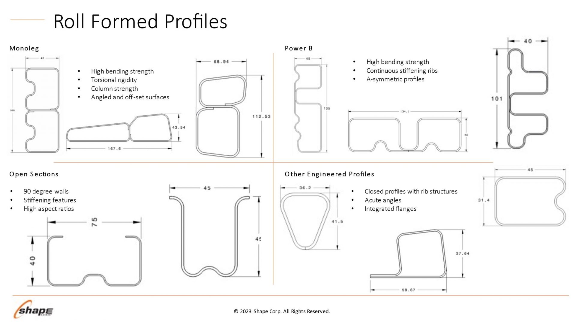
Figure 1 – Roll forming profile design possibilities. Courtesy of Shape Corporation.
Optimizing the use of roll forming requires understanding how the sheet metal behaves through the process. Making a bend in a roll-formed part occurs only when forming forces exceed the metal’s yield strength, causing plastic deformation to occur. Higher-strength sheet metals increase forming force requirements, leading to the need to have larger shaft diameters in the roll forming mill. Each pass must have greater overbend to compensate for the increasing springback associated with the higher strength.
Although a high-strength material requires greater forming loads, grades with higher yield strength can resist stretching of the strip edge and prevent longitudinal deformations such as twisting or bowing.
Force requirements for piercing operations are a function of the sheet tensile strength. High strains in the part design exceeding uniform elongation resulting from loads in excess of the tensile strength produce local necking, representing a structural weak point. However, assuming the design does not produce these high strains, the tensile strength has only an indirect influence on the roll forming characteristics.
Yield strength and flow stress are the most critical steel characteristics for roll forming dimensional control. Receiving metal with limited yield strength variability results in consistent part dimensions and stable locations for pre-pierced features.
Flow stress represents the strength after some amount of deformation and is therefore directly related to the degree of work hardening: starting at the same yield strength, a higher work hardening steel will have a higher flow stress at the same deformation.
Two grades are shown in Figure 2: ZE 550 and CR420Y780T-DP. ZE 550, represented by the red curve, is a recovery annealed grade made by Bilstein having a yield strength range of 550 to 625 MPa and a minimum tensile strength of 600 MPa, while CR420Y780T-DP, represented by the blue curve, is a conventional dual phase steel with a minimum yield strength of 420 MPa and a minimum tensile strength of 780 MPa. For the samples tested, ZE 550 has a yield strength of approximately 565 MPa, where that for CR420Y780T-DP is much lower at about 485 MPa. Due to the higher work hardening (n-value) of the DP steel, its flow stress at 5% strain is 775 MPa, while the flow stress for the HSLA grade at 5% strain is 620 MPa.
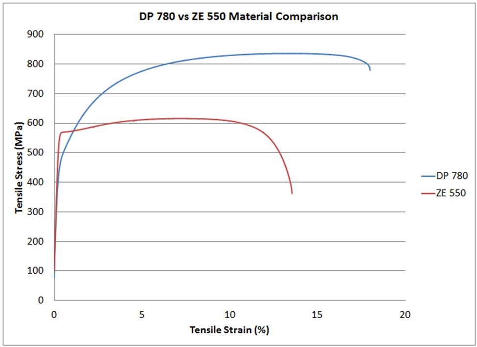
Figure 2 – Stress-strain curves for CR420Y780T-DP (blue) and ZE 550 (red). See text for description of the grades.
In conventional stamping operations, this work hardening is beneficial to delay the onset of necking. However, the use of dual-phase steels and other grades with high n-value can lead to dimensional issues in roll-formed parts. Flow stress in a given area is a function of the local strain. Each roll station induces additional strain on the overall part, and strains vary within the part and along the edge. This strength variation is responsible for differing springback and edge wave across a roll formed part.
Unlike conventional stamping, grades with a high yield/tensile ratio where the yield strength is close to the tensile strength are better suited to produce straight parts via roll forming.
Total elongation to fracture is the strain at which the steel breaks during tensile testing, and is a value commonly reported on certified metal property documents (cert sheets). As observed on the colloquially called “banana diagram”, elongation generally decreases as the strength of the steel increases.
For lower-strength steels, total elongation is a good indicator of a metal’s bendability. Bend severity is described by the r/t ratio or the ratio of the inner bend radius to the sheet thickness. The metal’s ability to withstand a given bend can be approximated by the tensile test elongation since, during a bend, the outermost fibers elongate like a tensile test.
In higher-strength steels where the phase balance between martensite, bainite, austenite, and ferrite plays a much larger role in developing strength and ductility than in other steels, microstructural uniformity usually limits bendability. Dual-phase steels, for example, have excellent uniform elongation and resistance to necking coming from the hardness difference between ferrite and martensite. However, this large hardness difference is also responsible for relatively poor edge stretchability and bendability. In roll-forming applications, those grades with a uniform microstructure will typically have superior performance. As an example, refer to Figure 2. The dual-phase steel shown in blue can be bent to a 2T radius before cracking, but the recovery annealed ZE 550 grade with noticeably higher yield strength and lower elongation can be bent to a ½T radius.
Remember that each roll-forming station only incrementally deforms the sheet, with subsequent stations working on a different region. Roll-formed parts do not need to use grades associated with high total elongation, especially since these typically have a bigger gap between yield and tensile strength.
We encourage you to visit https://ahssinsights.org/forming/roll-forming/roll-forming/ to learn more about roll forming and the types of coil shape that influence roll forming. Thank you to Brian Oxley and Dr. Daniel Schaeffler for providing this case study.

Brian Oxley, Product Manager, Shape Corporation, is a Product Manager in the Core Engineering team at Shape Corp. Shape Corp. is a global, full-service supplier of lightweight steel, aluminum, plastic, composite and hybrid engineered solutions for the automotive industry. Brian leads a team responsible for developing next generation products and materials in the upper body and closures space that complement Shape’s core competency in roll forming. Brian has a Bachelor of Science degree in Material Science and Engineering from Michigan State University.

Danny Schaeffler is the Metallurgy and Forming Technical Editor of the AHSS Applications Guidelines available from WorldAutoSteel. He is founder and President of Engineering Quality Solutions (EQS). Danny wrote the monthly “Science of Forming” and “Metal Matters” column for Metalforming Magazine, and provides seminars on sheet metal formability for Auto/Steel Partnership and the Precision Metalforming Association. He has written for Stamping Journal and The Fabricator, and has lectured at FabTech. Danny is passionate about training new and experienced employees at manufacturing companies about how sheet metal properties impact their forming success.
AHSS, Blog, homepage-featured-top, Joining, main-blog, News, Resistance Spot Welding, RSW of Dissimilar Steel, Steel Grades, Tool & Die Professionals
Urbanization and waning interest in vehicle ownership point to new transport opportunities in megacities around the world. Mobility as a Service (MaaS) – characterized by autonomous, ride-sharing-friendly EVs – can be the comfortable, economical, sustainable transport solution of choice thanks to the benefits that today’s steel offers.
The WorldAutoSteel organization is working on the Steel E-Motive program, which delivers autonomous ride-sharing vehicle concepts enabled by Advanced High-Strength Steel (AHSS) products and technologies.
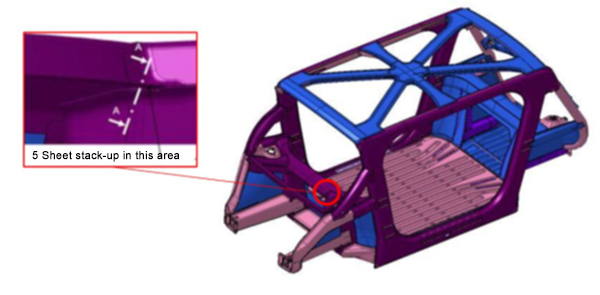
The Body structure design for this vehicle is shown in Figure 1. It also indicates the specific joint configuration of 5 layers AHSS sheet stack-up as shown in Table 1. Resistance spot welding parameters were developed to allow this joint to be made by a single weld. (The previous solution for this welded joint is to create one spot weld with the bottom 3 sheets indicated in the table and a second weld to join the top 2 sheets, combining the two-layer groups to 5T stack-up.)
NOTE: Click this link to read a previous AHSS Insights blog that summarizes development work and recommendations for resistance spot welding 3T and 4T AHSS stack-ups: https://bit.ly/42Alib8

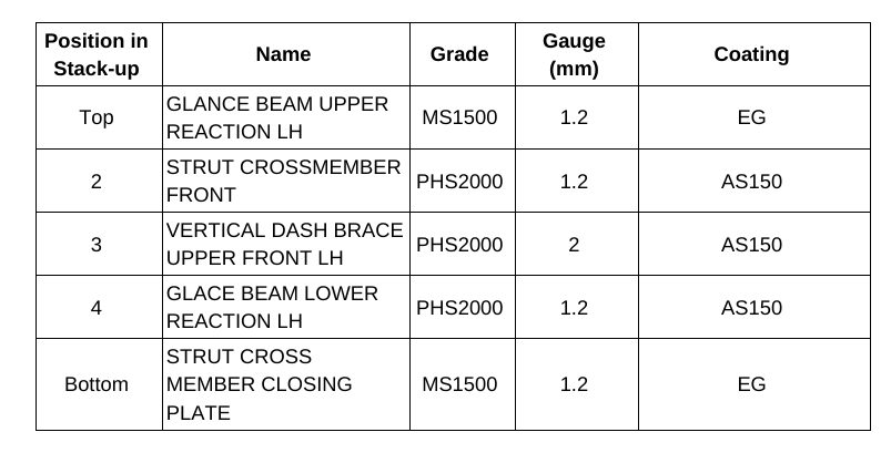
Table 1. Provided materials organized in stack-up formation showing part number, name, grade, gauge in mm, and coating type. Total thickness = 6.8 mm
The same approach of utilizing multiple current pulses with short cool time in between the pulses was shown to be most effective in this case of 5T stack-up. It is important to note that in some cases, the application of a secondary force was shown to be beneficial, however, it was not used in this example.
To establish initial welding parameters simulations were conducted using the Simufact software by Hexagon. As shown in Figure 2, the final setup included a set of welding electrodes that clamped the 5-layer AHSS stack-up. Several simulations were created with a designated set of welding parameters of current, time, number of pulses, and electrode force.
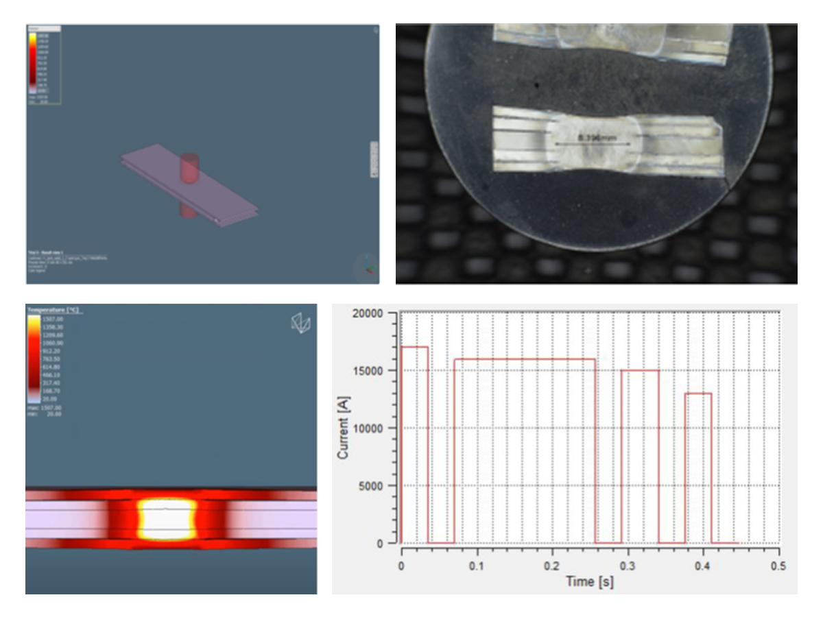
Figure 2. Example of simulation and experimental results showing acceptable 5T resistance spot weld (Meets AWS Automotive specifications)

Thanks is given to Menachem Kimchi, Associate Professor-Practice, Dept of Materials Science, Ohio State University and Technical Editor – Joining, AHSS Application Guidelines, for this article.
1stGen AHSS, 2ndGen AHSS, 3rdGen AHSS, AHSS, Blog, homepage-featured-top, main-blog, News, Production Managers, Steel Grades, Tool & Die Professionals
This month’s blog was contributed by Peter Ulintz, Precision Metalforming Association. This content originally appeared in the September 2023 issue of MetalForming Magazine under the title “Stronger AHSS Knowledge Required for Metal Stampers” and has been reproduced with the permission of MetalForming Magazine.
Metal stampers and die shops experienced with mild and HSLA steels often have problems making parts from AHSS grades. The higher initial yield strengths and increased work hardening of these steels can require as much as four times the working loads of mild steel. Some AHSS grades also have hardness levels approaching the dies used to form them.
Dies Get Tougher
Metal stampers and die shops experienced with mild and HSLA steels often have problems making parts from AHSS grades. The higher initial yield strengths and increased work hardening of these steels can require as much as four times the working loads of mild steel. Some AHSS grades also have hardness levels approaching the dies used to form them.
The higher stresses required to penetrate higher-strength materials require increased punch-to-die clearances compared to mild steels and HSLA grades. Why? This clearance acts as leverage to bend and break the slug out of the sheet metal. Stronger materials need longer levers to bend the slug. The required clearance is a function of the steel grade and tensile strength, and sheet thickness.
Increasing cutting clearance can result in punch cracking and head breakage due to higher snapthrough loads and reverse-unloading forces within the die. Adding shear angles to the punch face helps reduce punch forces and reverse unloading.
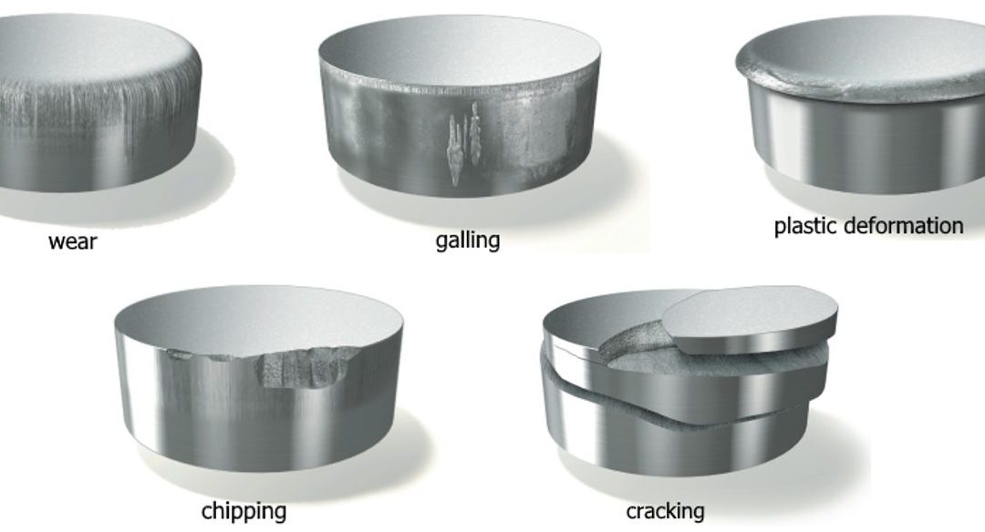
Tight-cutting clearances increase the tendency for die galling and chipping. The severity of galling depends on the surface finish and microstructure of both the tool steel and work material. Chipping can occur when process stresses are high enough to cause low-cycle fatigue of the tooling material, indicating that the material lacks toughness.
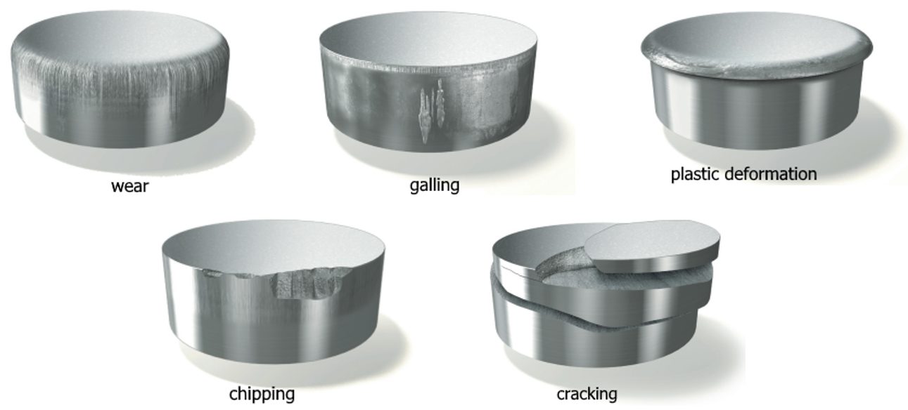
Stamping Tool Failure Modes (Citations T-20 and U-7)
Tempering of tools and dies represents a critical heat-treatment step and serves more than one purpose, but of primary concern is the need to relieve residual stresses and impart toughness. Dies placed in service without proper tempering likely will experience early failure.
Dies made from the higher-alloy tool-steel grades (D, M or T grades) require more than one tempering step. These grades contain large amounts of retained austenite and untempered martensite after the first tempering step and require at least one more temper to relieve internal stresses, and sometimes a third temper for even greater toughness.
Unfortunately, heat treatment remains a “black-box” process for most die shops and manufacturing companies, which send soft die details to the local heat treat facility, with hardened details returned. A cursory Rockwell hardness test may be conducted at the die shop when the parts return. If they meet hardness requirements, the parts usually are accepted, regardless of how they may have been processed—a problem, as hardness alone does not adequately measure impact toughness.
Machines Get Stronger
The increased forces needed to form, cut and trim higher-strength steels create significant challenges for pressroom equipment and tooling. These include excessive tooling deflections, damaging tipping-moments, and amplified vibrations and snapthrough forces that can shock and break dies—and sometimes presses. Stamping AHSS materials can affect the size, strength, power and overall configuration of every major piece of the press line, including material-handling equipment, coil straighteners, feed systems and presses.
Here is what every stamper should know about higher-strength materials:
- Because higher-strength steels require more stress to deform, additional servo motor power and torque capability may be needed to pull the coil material through the straightener. Additional back tension between the coil feed and straightening equipment also may be required due to the higher yield strength of the material in the loop as the material tries to push back against the straightener and feed system.
- Higher-strength materials, due to their greater yield strengths, have a greater tendency to retain coil set. This requires greater horsepower to straighten the material to an acceptable level of flatness. Straightening higher-strength coils requires larger-diameter rolls and wider roll spacing in order to work the stronger material more effectively. But increasing roll diameter and center distances on straighteners to accommodate higher-strength steels limits the range of materials that can effectively be straightened. A straightener capable of processing 600-mm-wide coils to 10 mm thick in mild steel may still straighten 1.5-mm-thick material successfully. But a straightener sized to run the same width and thickness of DP steel might only be capable of straightening 2.5 mm or 3.0-mm thick mild steel. This limitation is primarily due to the larger rolls and broadly spaced centers necessary to run AHSS materials. The larger rolls, journals and broader center distances safeguard the straightener from potential damage caused by the higher stresses.
- Because higher-strength materials require greater stress to blank and punch as compared to HSLA or mild steel, they generate proportionally increased snapthrough and reverse-unloading forces. High-tensile snapthrough forces introduce large downward accelerations to the upper die half. These forces work to separate the upper die from the bottom of the ram on every stroke. Insufficient die-clamping force could cause the upper-die half to separate from the bottom of the ram on each stroke, causing fatigue to the upper-die mounting fasteners.
- Because energy is expended with each stroke of the press—and this energy must be replaced—critical attention must focus on the size (horsepower) of the main drive motor and the rotational speed of the flywheel in higher-strength-steel applications. The main motor, with its electrical connection, provides the only source of energy for the press and it must generate sufficient power to meet the demands of the stamping operation. The motor must be properly sized to replace the increased energy expended during each press stroke. For these reasons, some stampers consider the benefits of servo-driven presses for these applications.
As steels becomes stronger, a corresponding increase in process knowledge is required in terms of die design, construction and maintenance, and equipment selection.
You can read more about these topics at these links:
Tooling and Die Wear
Coil Processing Straightening and Leveling
Press Requirements

Thanks go to Peter Ulintz, of the Precision Metalforming Association (PMA) for authoring this article. Ulintz was employed in the metal stamping and tool & die industries for 38 years before joining Precision Metalforming Association (PMA) in 2015. He provides industry-related training and seminars in Stamping Press Operation and Setup; Designing and Building Metal Stamping Dies; Die Maintenance and Troubleshooting; Metal Stamping Design for Manufacturability; Deep Draw Tooling and Process Technology; Stamping Higher Strength Steels; and Problem Solving in the Press Shop. Peter is a contributor to ASM Handbook, Volume 14B, Metalworking: Sheet Forming (2006) and writes the monthly column, Tooling by Design, for PMA’s monthly publication, MetalForming Magazine.


