Vehicle programs must balance performance, safety, fuel efficiency, affordability and the environment, while maintaining designs that are appealing to customers. Use of higher strength steels allows for a reduction in the sheet metal thickness and in turn vehicle mass. The increased ductility offered by Advanced High Strength Steels facilitates part consolidation also contributing to lower weight and manufacturing cost while providing an efficient way to increase component and vehicle stiffness.
Low-density materials like aluminium, magnesium and composites have widespread use in luxury class vehicles, where amenities, comfort, and speed are prioritized over affordability. Penalties for not meeting fuel economy and emissions mandates are easily absorbed in the sales price.
On mass-market vehicles, where per-unit emissions are multiplied over higher volumes, automakers target selecting the most efficient way to achieve the lowest total emissions.
Compared with the limited number of low-ductility steels available decades ago, the lower density materials would have offered an easy but costly path to lightweighting. Back then, since there were not that many high-strength options, vehicle crashworthiness was improved by increasing thickness.
However, increasing metal strength allows for a thickness reduction while maintaining crash performance. The substantially higher strength steels available today have sufficient ductility to form complex stampings from sheets thin enough to be weight-competitive with components formed from lower-density materials that must be made from higher thickness to have comparable stiffness.
The spectrum of steel grades commercially available today have:
- higher strength, greatly contributing to the crash-energy management approach.
- higher ductility that allows for additional shape to be formed into the component, also increasing stiffness and potentially allowing for part consolidation,
- higher modulus than aluminium or magnesium that inherently leads to a stiffer component.
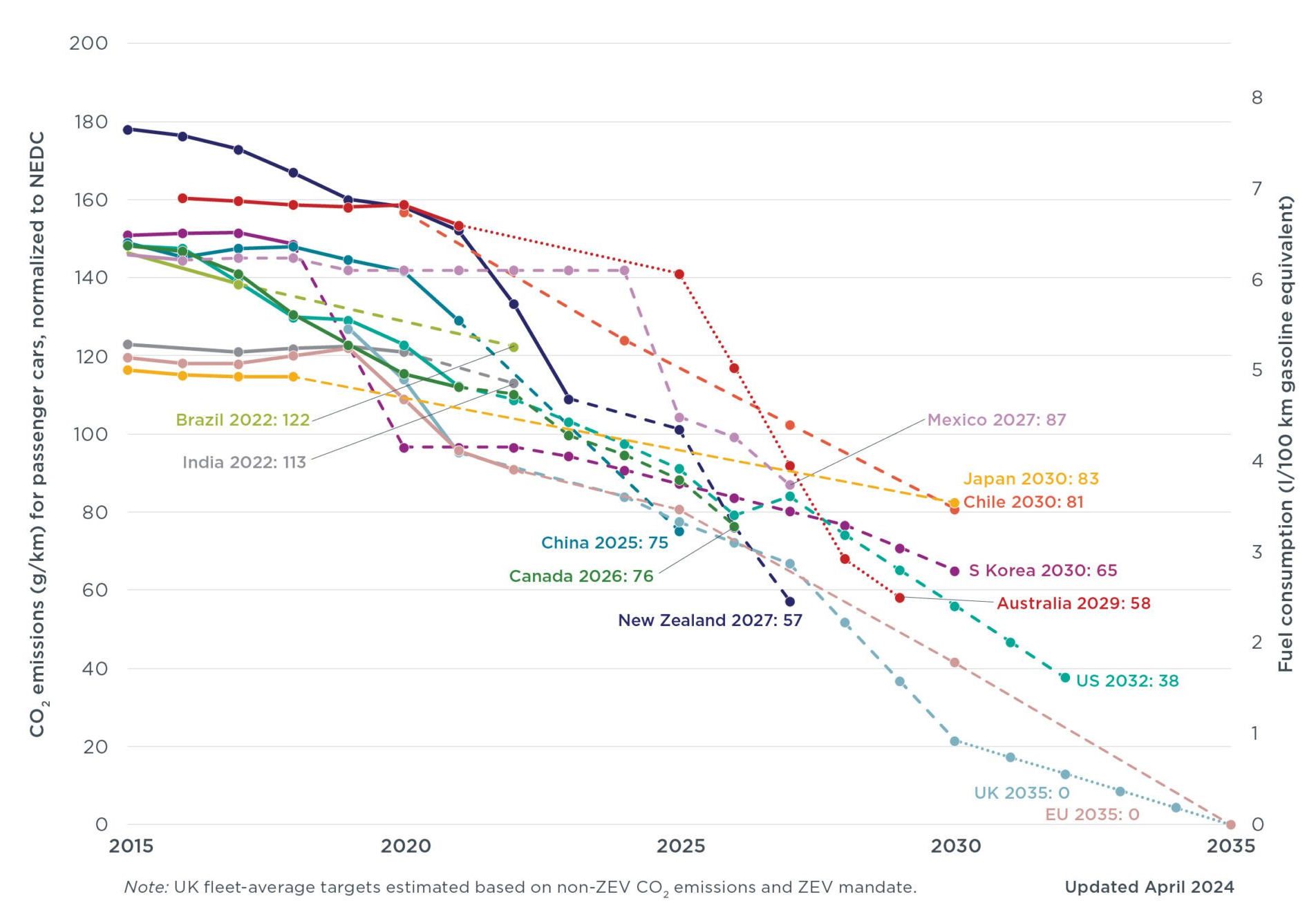
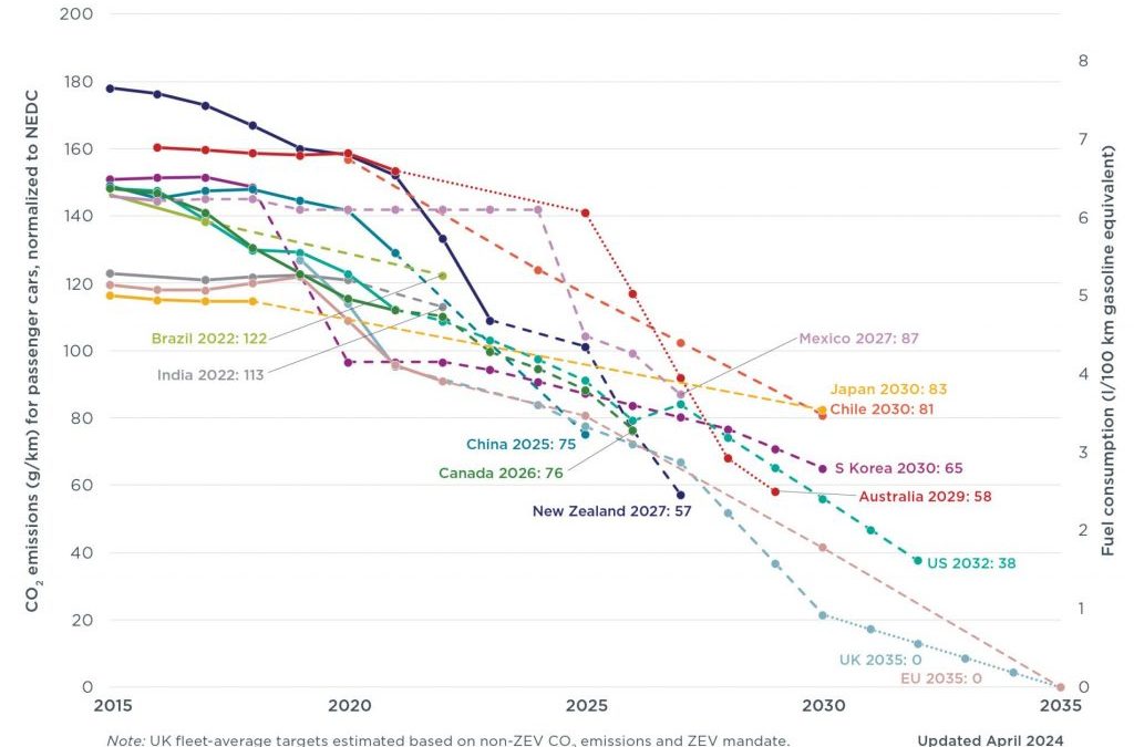
Recent years have seen an increased global sensitivity to tailpipe emissions, with Figure 1 highlighting regulations for passenger cars in different countries and regions. Many major markets have committed to fleet average emissions below 100 g CO2/km, and we’re on a negotiated global journey to Net Zero Emissions by 2050.
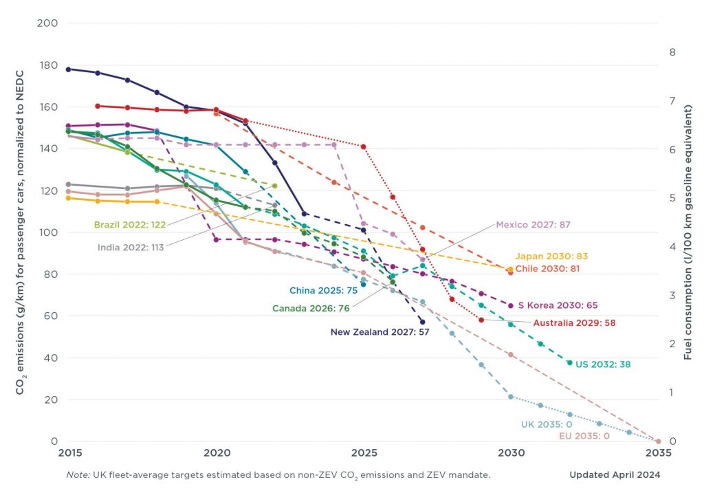
Figure 1: Passenger car emissions and fuel consumption targets, normalized to New European Driving Cycle I-2
The problem with the current regulation of automotive greenhouse gas (GHG) emissions is their focus solely on tailpipe emissions, produced from fuel combustion during vehicle use. The regulations ignore other significant sources of GHG emissions in the vehicle’s life cycle including vehicle production (including the emissions from material production) and treatment of the vehicle at the end of its useful life. This omission comes with serious risks. An unintended effect of this approach is an over-emphasis on vehicle lightweighting. While lightweighting can be an effective tool to reduce vehicle emissions, it must be done with a holistic knowledge of the implications related to the total vehicle life cycle GHG emissions.
Reducing vehicle mass decreases fuel consumption, which also reduces tailpipe emissions. This may, or may not, offset the increased production emissions from material production of the lower density materials. One possibility is that the reduction of emissions in the use phase results in overall lower emissions, but because of the trade-off between the use phase and production emissions, the result is not as low as predicted by a tailpipe-only metric – some of the use-phase savings is offset by the increased production emissions. Also possible is where the use phase savings and the production phase increase are approximately equal, resulting in no net savings at all. In the other extreme, the production emissions outweigh the use phase savings, resulting in the unintended consequences of an increase in the overall emissions. This last scenario is the very opposite of what government policy intends, but happens regularly when vehicles constructed with low density materials don’t reach their intended vehicle life.
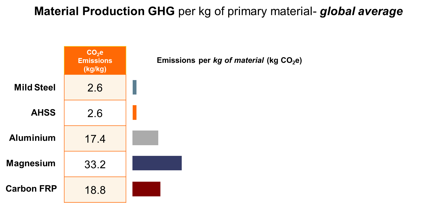
One of the perceived advantages to using materials of lower density is the expectation that they will result in lower GHG emissions. To illustrate why this is not true, consider the emissions from the material production stage of a typical automotive component. The mid-range GHG values for each material are taken from the above chart and then multiplied by the projected material weight that is required to make a hypothetical component. (The actual mass for an equivalent component varies based on the material used and the component design.)

Figure 2: Material average GHG emissions from primary production, in kg CO2e per kg of material.W-40
Furthermore, low-density materials create an offsetting emissions problem, as production of these materials is GHG-intensive, and therefore costly to the environment. The production of these alternative materials can produce 7 to 20 times more emissions than steel, as shown in Figure 2.

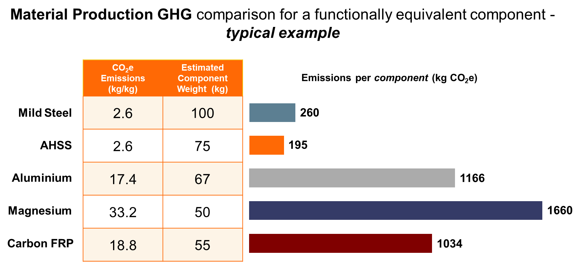
Figure 3: Material GHG emissions in kg CO2e for functionally equivalent generic components.W-40
Figure 3 shows that the use of lower density materials does not necessarily mean a reduction in greenhouse gas emissions. Although less weight is required for some alternative materials to achieve the same component functional performance, the emissions from the material production stage can still be many times higher than those of the baseline component. Therefore, the increase in material production emissions may outweigh the reduction in use phase emissions even after factoring in the mass savings benefit.
Vehicles are transitioning to alternative-energy powertrains and away from those based on fossil fuels. In these new-energy vehicles powered entirely by renewable electricity, emissions from the vehicle production stage, which includes material production, could account for as much as 95% of total emissions. In this scenario, the usage phase accounts for a mere 5% of the lifetime emissions. This is the opposite of what is found with vehicles having conventional Internal Combustion Engine (ICE) powertrains. For this reason, use of low GHG material such as steel becomes even more important as the world moves towards a renewable future.
Life Cycle Assessment
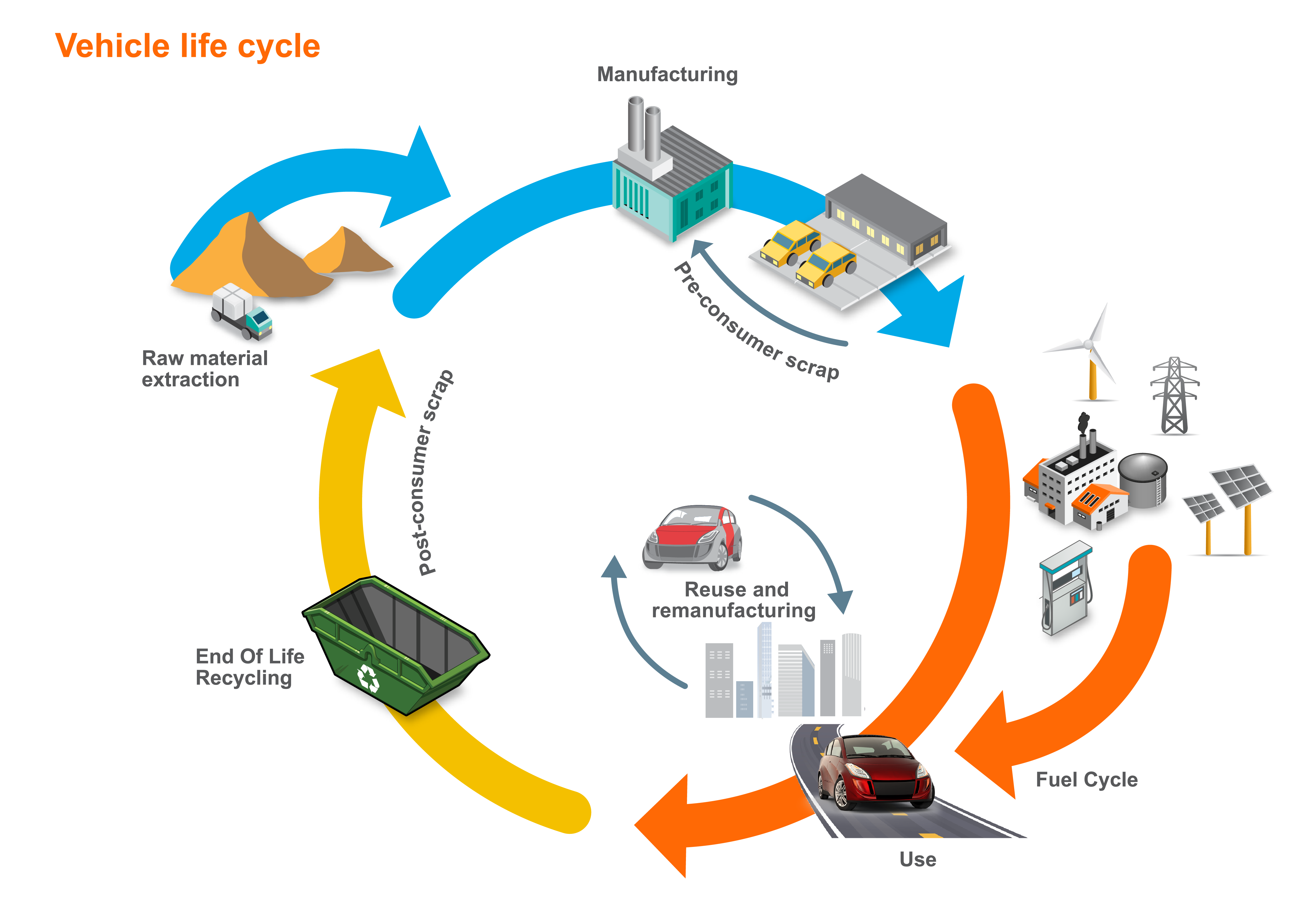
Life Cycle Assessment (LCA) is an environmental accounting methodology that considers a product’s entire life cycle, with cradle-to-grave assessments typically including impacts from raw material extraction and production (manufacturing phase), through its useful life (use phase), and to the end-of-life disposal or recycling of the product (end-of-life phase). It also takes into account the full life cycle of energy sources used across all lifecycle phases. This process illuminates any potential trade-offs between phases and highlights the true environmental impact, beyond the focus on tailpipe-only emissions.
Recent years have seen a greater adoption of using Life Cycle Assessment to assess a vehicle’s true environmental impact rather than solely focusing on what comes out of the tailpipe. LCA accounts for the total emissions including those coming from material production, vehicle use, and the chosen end-of-life path. The principles, framework, requirements and guidelines for Life Cycle Assessment are laid out in international standards ISO 14040I-3 and ISO 14044I-4.
Most major OEMs utilize some form of life cycle thinking or LCA, recognizing its importance and effectiveness in product and process design. Material producers also accept and use LCA. Together with many of their member companies, the trade associations of the steel, aluminium, and plastics industries are among the most active members of the global LCA community.
The European Union requires accounting for embedded lifecycle emissions. Following a phase-in period, there will be monetary penalties assessed against companies not providing this information. These requirements will drive OEMs to demand pertinent details from all of their material suppliers.
Environmental policies target achieving a total net reduction in emissions, including GHG (measured in carbon dioxide equivalents, or CO2e, that is a measure of all greenhouse gases attributable to a product that affect global warming potential. Thus, CO2e includes gases other than CO2.
Properly applied, LCA enables automakers to ensure that improvements in one phase are not offset by worse performance in another phase. This assessment of potential trade-offs is critical to environmental improvement. For example, if the increase in production emissions of a lightweight material is greater than the decrease in use phase emissions, vehicle light-weighting in this manner counter-productively increases total emissions.
LCA can be used to assess a broad array of environmental impacts beyond the global warming potential of greenhouse gases, including acidification, ecotoxicity, and ozone depletion.
The Path To Net Zero Emissions
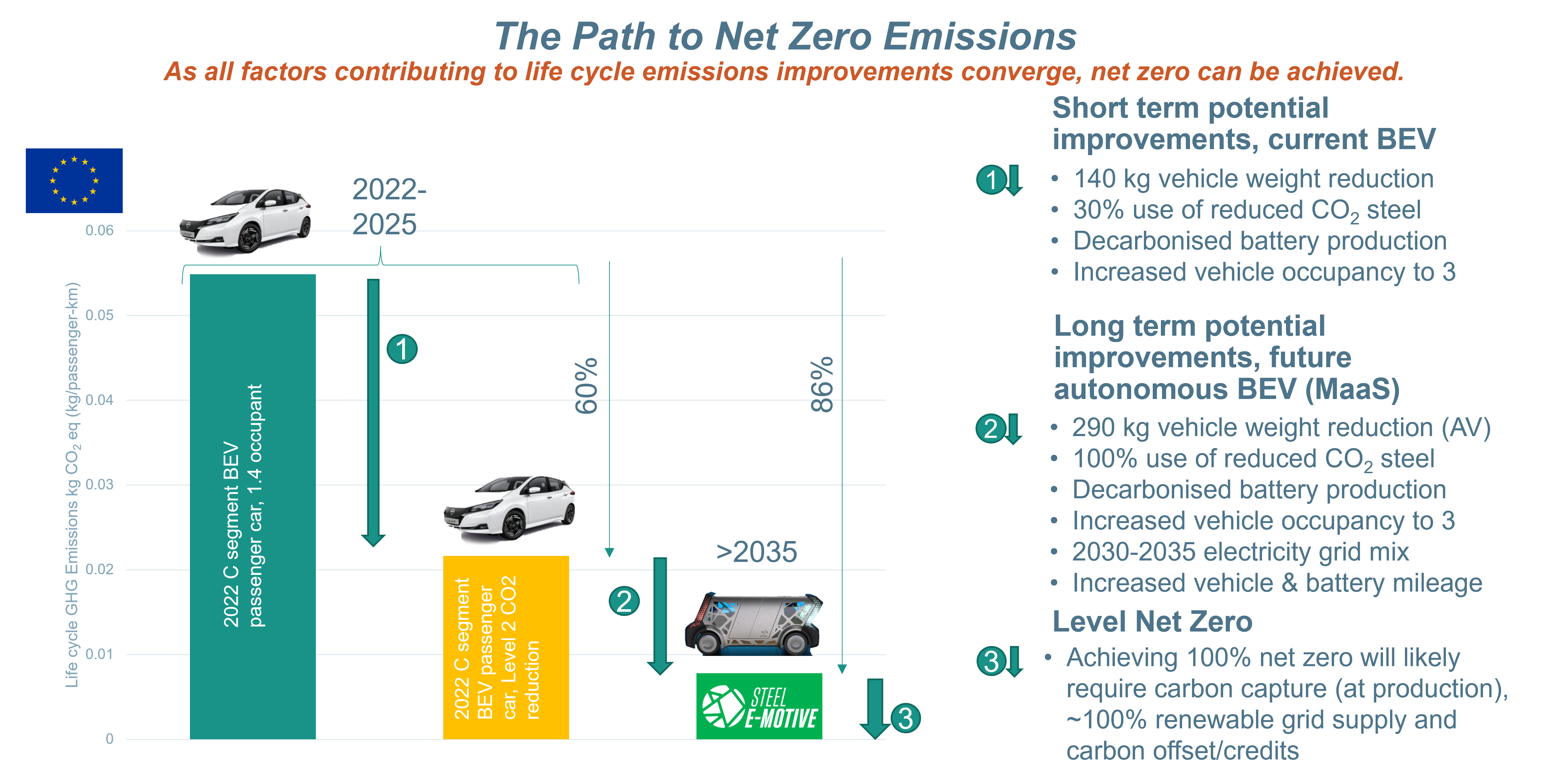
Fully autonomous Mobility as a Service vehicles such as the Steel E-Motive concept have the potential to address the ongoing and future requirements for decarbonisation of passenger transportation. Figure 4 shows the emissions walk-down beginning with a present-day C-sized BEV operating as a taxi.
Near term, a 60% reduction in Life Cycle emissions can be realized by an increased use of reduced CO2 steel and decarbonized battery production, along with an increased use of ride-sharing. Through 2035, as all available emissions reduction strategies are deployed – including autonomous MaaS vehicles with increased occupancy and extended vehicle and battery lives – an 86% reduction in emissions from a 2022 baseline is feasible.
Achieving Net Zero post 2035 requires carbon capture technologies, 100% renewable grid supplies, and carbon offsets or credits.
Each of these steps are described in detail within the Steel E-Motive Engineering Report.
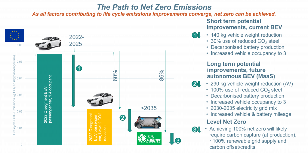
Figure 4: The Path to Net Zero Vehicle Emissions
Blog, homepage-featured-top, main-blog, News
The transportation industry’s contribution to greenhouse gas (GHG) emissions and global warming is well documented and understood. Vehicle OEMs, fleet operators, and transport users all have responsibilities to reduce environmental impacts on the planet and contribute to meeting global emissions regulations.
Mobility as a Service (MaaS) solutions like WorldAutoSteel’s flaghip Steel E-Motive (SEM) program have the potential to contribute to a reduction in GHG emissions, helping to achieve these global targets and specific policy objectives. The Steel E-Motive engineering report, released in 2023, addresses the impact of emissions reduction using Life Cycle Assessment, with key results summarized in this article.
Introduction to Life Cycle Assessment
Life Cycle Assessment (LCA) is a methodology that evaluates the environmental impact of a product across its entire lifecycle. By understanding the impact across the entire vehicle life cycle, vehicle manufacturers evaluate trade-offs and assess the net impact of the product they’re using.
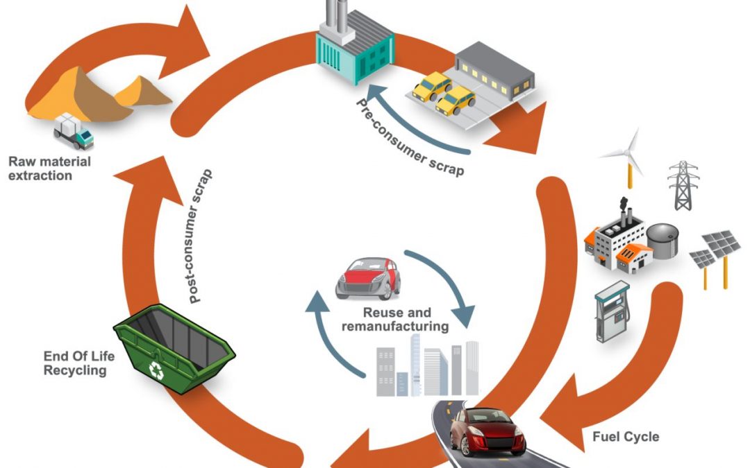
Cradle-to-grave assessments utilize a boundary that includes impacts from the production phase (including raw material extraction and vehicle production), the use phase (including fuel or electricity as well as consumables like tires and fluids) and the end-of-life phase, which could include disposal and/or recyling of the product, as shown in Figure 1. We applied LCA throughout the development of the SEM concept.
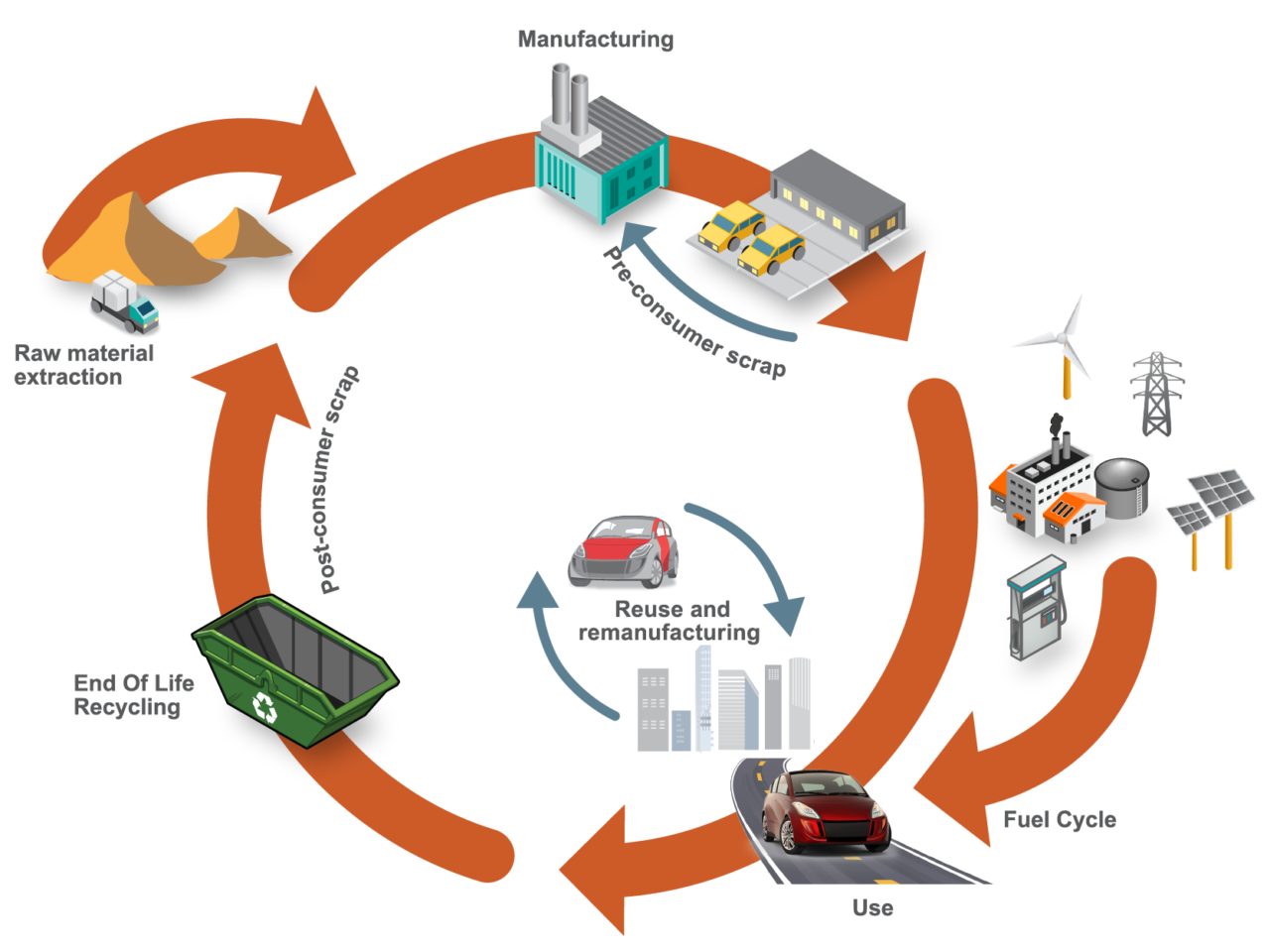
Figure 1. SEQ Figure \* ARABIC 1 Life Cycle Assessment, considering the entire life of the vehicle, from raw material extraction to end of life
LCA can cover a range of environmental impacts; however, for the SEM program, we focused on GHG emissions through the GWP-100 indicator and total energy consumption using Cumulative/Primary Energy Demand and Fossil Energy Consumption indicators.
Reference Taxi (Baseline) Vehicle
A key consideration in LCA calculations is establishing an appropriate reference vehicle. For this program, the following criteria was used:
- Present day (~2020) battery electric vehicle (BEV) operating in taxi mode with a driver and one occupant with vehicle/battery lifetime assumptions of 300,000km, and use of 100 percent conventional steel/aluminum.
- Vehicle end-of-life methodology using the Avoided Burden Approach, where recycled metals are assumed to displace equivalent quantities of their virgin counterparts and assigned corresponding emission and energy demand credits.
- Assumption of 50 percent pyrometallurgical recycling for the battery packs.
- Estimated reference taxi vehicle curb weight using the statistical reference data study (Figure 2), resulting in an estimated curb weight of 1,949kg.
- Material utilization based on data from a similar vehicle specification, as shown in Figure 3.
- Vehicle occupancy rate assumptions of 1.4, based on a combination of both “empty” and passenger-carrying journeys.
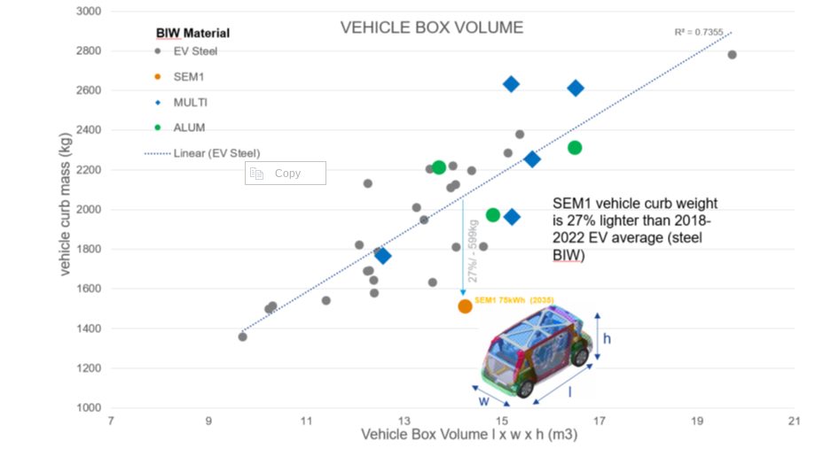
Figure 2. Vehicle curb weight versus box volume comparison. Reference vehicle data; source www.a2mac1.com
Steel E-Motive “Default” Vehicle
SEM vehicle life cycle calculations assume a hypothetical 2030 manufacture and start-of-operation date of 2030 to 2035. We updated the electricity grid supply mix to include the average of the International Energy Agency (IEA) scenario estimates for 2030 and 2040.
- We applied the nominal SEM1 vehicle curb weight of 1,512kg in the LCA model, and updated the vehicle Bill of Materials.
- As with the reference vehicle, we adopted the Avoided Burden Approach as the default for end-of-life calculation.
Life Cycle Assessment Results
Figure 3 below highlights absolute calculated life cycle GHG emissions, in units of kgCO2e/ passengerꞏkilometer studied, with the individual contributions of vehicle manufacturing, vehicle use, and end-of-life phase presented.
The analysis evaluated two reference/baseline conditions and nine SEM sensitivity studies, see Figure 4. These included alternative assumptions on LCA end-of-life modeling methodology, lifetime vehicle activity (and battery lifetime), alternative operational energy consumption sensitivities, sensitivities on the use of ‘green’ steel, and vehicle occupancy rates.
The accompanying pie chart shows the breakdown and contributions to the vehicle manufacture GHG for the baseline SEM scenario (2).
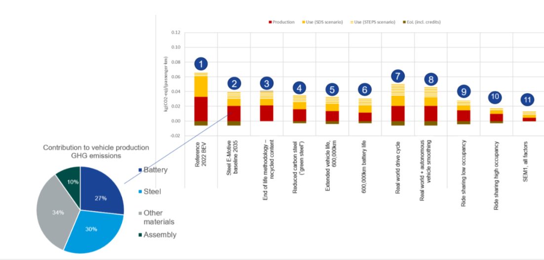
Figure 3. SEQ Figure \* ARABIC 2 life cycle assessment GHG results
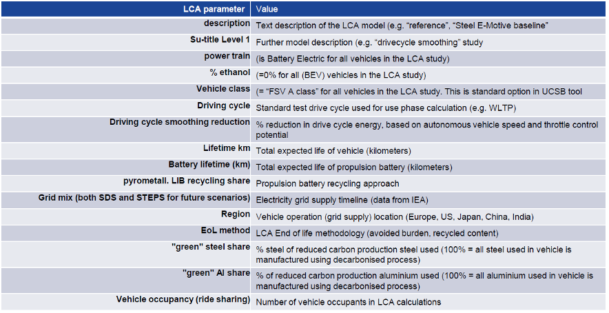
Figure 4. Reference/baseline conditions and SEM sensitivity studies
Life Cycle Assessment Conclusions
Based on the parameters outlined, applying LCA to SEM concept demonstrated the designs’ potential to reduce lifecycle greenhouse gas emissions by up to 86 percent compared to a present-day battery electric vehicle operating as a taxi.
This potential can be realized by adopting the following measures:
- Reducing vehicle production and manufacturing embedded emissions by utilizing 100 percent reduced carbon (“green”) steel
- Improving battery technology and increasing the use of renewable electricity in battery manufacturing; as well as increasing/improving battery recycling
- Ensuring the vehicle weight of autonomous vehicles is managed, and the potential weight reduction benefits realized and implemented. The SEM body structure and battery housing demonstrate good weight efficiency.
- Increasing the overall lifespan of the vehicle and battery. The fatigue and durability properties of AHSS can enable enhanced vehicle lifetime. The SEM battery design allows easy replacement of specific modules, enabling an overall extended battery life.
- Autonomous vehicle control smooths the driving cycle. The vehicle acceleration and deceleration rates can be optimized to match the driving conditions and road topography, reducing energy consumption and subsequent GHG emissions.
- Increasing passenger occupancy rates to at least three per vehicle via MaaS.
The projected net GHG emissions for the SEM vehicle operating with the flexibilities described above already represent a significant reduction when compared to the current baseline.
Achieving net zero emissions would require additional measures like offsetting manufacturing impacts (e.g., through compensatory credits from atmospheric carbon capture and storage) and transitioning to a 100 percent renewable electricity grid.
Moving Toward Net Zero
Taking a Life Cycle Assessment approach to the SEM concept demonstrates the possibilities for engineering future mobility vehicles that continue to move us closer to a net zero future. For more information about the Steel E-Motive program, download the engineering report here: https://bit.ly/SEM_Eng_Report

Thanks go to Russ Balzer for his contribution of this article to the AHSS Insights blog. As.technical director at WorldAutoSteel, he leads technical programs and oversees the organization’s work in research, modeling, and advocacy for Life Cycle Assessment in the automotive sector. An LCA Certified Professional through the American Center for Life Cycle Assessment (ACLCA), he also acts as the WorldAutoSteel liaison to the worldsteel LCA Expert Group.

Blog
Life Cycle Assessment (LCA), and particularly vehicle product life cycle assessment, is a topic we are very passionate about here at WorldAutoSteel. So much so that we focus on LCA intensively for the entire month of October across all of our communications channels. Though it’s not an AHSS forming or joining topic, it is one that is critical to truly reducing vehicle emissions for future generations. Russ Balzer, Technical Director at WorldAutoSteel and our resident LCA professional, in this blog and the next, will talk about LCA, its importance, and the tools WorldAutoSteel has developed to provide environmental insight to design decision tradeoffs.
All over the world there are continuing and growing efforts to address transportation greenhouse gas (GHG) emissions, which remain a major unresolved issue. These efforts are intended to help the transportation sector make its contribution to global emissions reduction goals. Unfortunately, much of this effort is focused on reducing emissions only from the vehicle tailpipe, with no consideration of the other sources of emissions in that vehicle’s life. This is not an effective way to meet these goals. In fact, this approach could lead to the unintended consequence of increasing GHG emissions in some cases. Fortunately, there is a better way – life cycle assessment (LCA), a tool for looking at the environmental impact of a product across its entire life cycle (Figure 1).

Figure 1: Vehicle LCA encompasses all phases of the product cycle, from raw material extraction to end of life recycling and disposal.
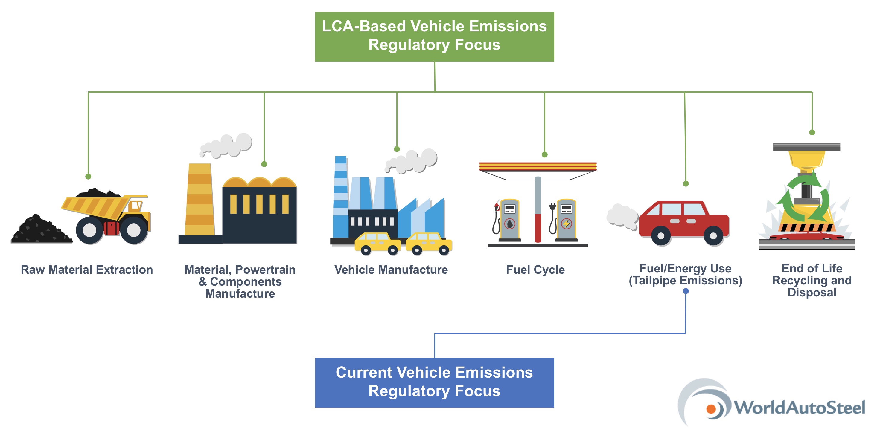
Focusing solely on the tailpipe emissions means ignoring other significant sources of GHG emissions, such as vehicle production and emissions generated (or avoided) at the end of the vehicle’s useful life (see Figure 2 on Page 2). An example of this is that tailpipe-only thinking can put too much emphasis on lightweighting. Don’t get me wrong, lightweighting can be an important part of the solution. Three of the four main drivers of fuel consumption (and therefore tailpipe emissions) – rolling resistance, acceleration and gravity (as in climbing a hill) – are dependent on the vehicle’s mass. So we can see why vehicle lightweighting is an obvious choice. It is a direct way to reduce these power demands and achieve better fuel consumption and fewer tailpipe emissions. The problem with lightweighting arises when we are so focused on reducing a vehicle’s mass that we fail to consider the consequences to the vehicle’s overall emissions.
One of the potential consequences arises from the use of lower-density materials like aluminium, magnesium and even carbon fibre to replace steel in a vehicle. From a tailpipe perspective, this can seem like a good (if expensive) solution. Vehicle mass may be reduced, resulting in improved fuel consumption and fewer tailpipe emissions. Sadly, it is not that simple. These low-density materials come with an environmental cost in addition to their higher financial cost. This cost comes in the form of higher GHG emissions in the production of the material itself. On a global average basis, GHG emissions from aluminium production can be as much as eight times as high per kilogram of material as the GHG emissions from steel production. For carbon fibre and magnesium the difference in production GHG emissions is even greater. This means that, even though you may save tailpipe emissions with some applications of these low-density materials, there is always a trade-off of higher production emissions.

Figure 2: The difference between a regulatory focus that includes LCA and current tailpipe emissions.
In the best case, the reduction of emissions in the use phase does result in overall lower emissions, though, because of the trade-off between the tailpipe and production emissions, not as low as predicted by a tailpipe-only metric. Also possible is an intermediate case in which the use phase savings and the production phase increase are approximately equal, resulting in no net savings at all. In the worst case, the production emissions outweigh the use phase savings, resulting in the unintended consequence—higher overall emissions, the very opposite of what the regulation intends.
All three of these cases have two things in common. First, under a tailpipe-only regulation, we don’t know what the actual emissions are, because production emissions impacts are not being monitored. Second, because the low-density materials we are talking about are more expensive, all three of these cases come at a higher cost. So, we must ask ourselves: do we want to force automakers and consumers to pay more money without knowing the outcome? It’s time to consider another route to reducing emissions, and we believe that taking a life cycle approach is the correct route.
LCA assesses all the stages of a product’s life, from raw material extraction through production, use, and end of life processing. Though awareness of LCA has grown rapidly over the last 10-15 years, LCA methodology and practice have been developing since the early 1970s. Today, it is a mature assessment tool with global standards. Many car manufacturers are already using life cycle thinking and LCA, recognizing its importance and effectiveness in product and process design. LCA is equally accepted and used by material producers. In fact, together with many of their member companies, the trade associations of the steel, aluminium, and plastic industries are among the most active members of the global LCA community.
WorldAutoSteel has been directly involved with LCA since 2007, when we partnered with Dr. Roland Geyer of the University of California at Santa Barbara to develop an LCA tool for the assessment of material choices in passenger vehicles. The UCSB Automotive Materials Energy and Green House Gas (GHG) Comparison Model that Dr. Geyer developed on behalf of WorldAutoSteel is now in its fifth version and continues to be one of the most comprehensive publicly available vehicle LCA tools in the world.
The UCSB model is a full vehicle model assessing both GHG and energy effects of automotive material substitution over the entire life cycle of the vehicle.
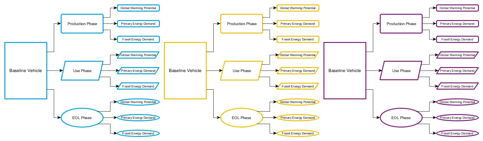
Computation and parameter values are kept separate for maximum transparency and flexibility. This allowed the computational structure to be peer reviewed by members of the LCA community. The model calculates 27 main result values: three environmental indicators x three life cycle stages x three vehicles, as shown in Figure 3.
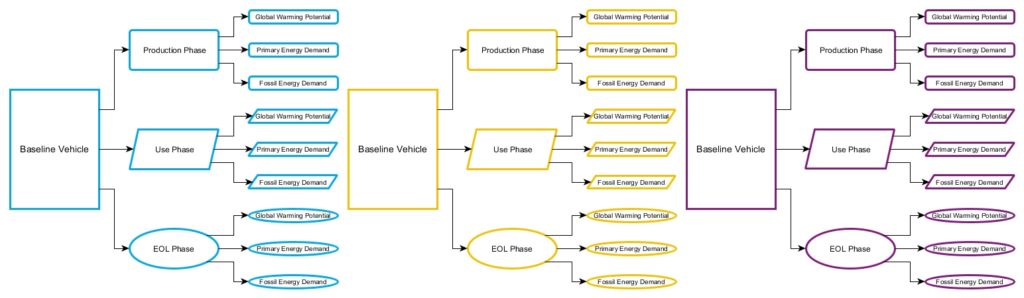
Figure 3: UCSB Model calculates 27 main result values.
The model has the flexibility to allow a multitude of different scenario evaluations, offering 14 structural material categories, 24 total material categories, adjustable material recycling methodology, a variety of biofuel and electricity pathways, as well as the powertrains, driving cycles and vehicle classes noted in Figure 4.

Figure 4: UCSB Model analysis options.
To maximize flexibility and transparency, all calculations are shown, and no parameter values are locked or hidden. This makes the UCSB Model an excellent tool for teaching LCA, particularly automotive LCA.
GHG emissions in the transport sector must be reduced to meet global emissions reduction goals. Lightweighting of passenger vehicles can be an important part of the emissions reduction solution in the transport sector, but only if lightweighting scenarios are viewed in the context of the overall vehicle emissions. Many companies inside and outside of the transport sector use Life Cycle Assessment, which considers environmental impacts from the whole of a vehicle’s life cycle, as their primary method to develop this overall view. The UCSB Automotive Energy and GHG Model, developed on behalf of WorldAutoSteel, is a publicly available, peer-reviewed tool for the assessment of automotive emissions on a life cycle basis. Version 5 of the UCSB Model can be downloaded for free at the WorldAutoSteel website here.
At the UCSB Model download page, you’ll find a video workshop featuring Russ Balzer explaining the contents of the Model. A user guide is also available for download.

Russ Balzer, Technical Director, WorldAutoSteel
Russ Balzer is the LCA Technical Director at WorldAutoSteel and Phoenix Group. As Technical Director, Russ manages a variety of engineering projects, and has tactical and strategic responsibilities in WorldAutoSteel’s efforts to use and promote Life Cycle Assessment (LCA). Russ recently achieved ACLCA LCACP certification and was recognized for his work in the field of LCA with the ACLCA’s Rising Star Award.