Blog, homepage-featured-top, main-blog, News, Resistance Spot Welding, RSW of Dissimilar Steel, Tool & Die Professionals
Urbanization and waning interest in vehicle ownership point to new transport opportunities in megacities around the world. Mobility as a Service (MaaS) – characterized by autonomous, ride-sharing-friendly EVs – can be the comfortable, economical, sustainable transport solution of choice thanks to the benefits that today’s steel offers.
The WorldAutoSteel organization is working on the Steel E-Motive program, which delivers autonomous ride-sharing vehicle concepts enabled by Advanced High-Strength Steel (AHSS) products and technologies.
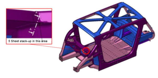
The Body structure design for this vehicle is shown in Figure 1. It also indicates the specific joint configuration of 5 layers AHSS sheet stack-up as shown in Table 1. Resistance spot welding parameters were developed to allow this joint to be made by a single weld. (The previous solution for this welded joint is to create one spot weld with the bottom 3 sheets indicated in the table and a second weld to join the top 2 sheets, combining the two-layer groups to 5T stack-up.)
NOTE: Click this link to read a previous AHSS Insights blog that summarizes development work and recommendations for resistance spot welding 3T and 4T AHSS stack-ups: https://bit.ly/42Alib8
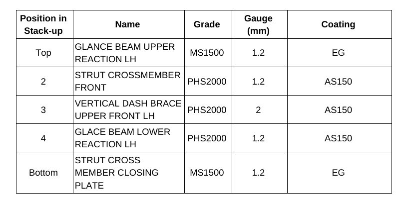
Table 1. Provided materials organized in stack-up formation showing part number, name, grade, gauge in mm, and coating type. Total thickness = 6.8 mm
The same approach of utilizing multiple current pulses with short cool time in between the pulses was shown to be most effective in this case of 5T stack-up. It is important to note that in some cases, the application of a secondary force was shown to be beneficial, however, it was not used in this example.
To establish initial welding parameters simulations were conducted using the Simufact software by Hexagon. As shown in Figure 2, the final setup included a set of welding electrodes that clamped the 5-layer AHSS stack-up. Several simulations were created with a designated set of welding parameters of current, time, number of pulses, and electrode force.
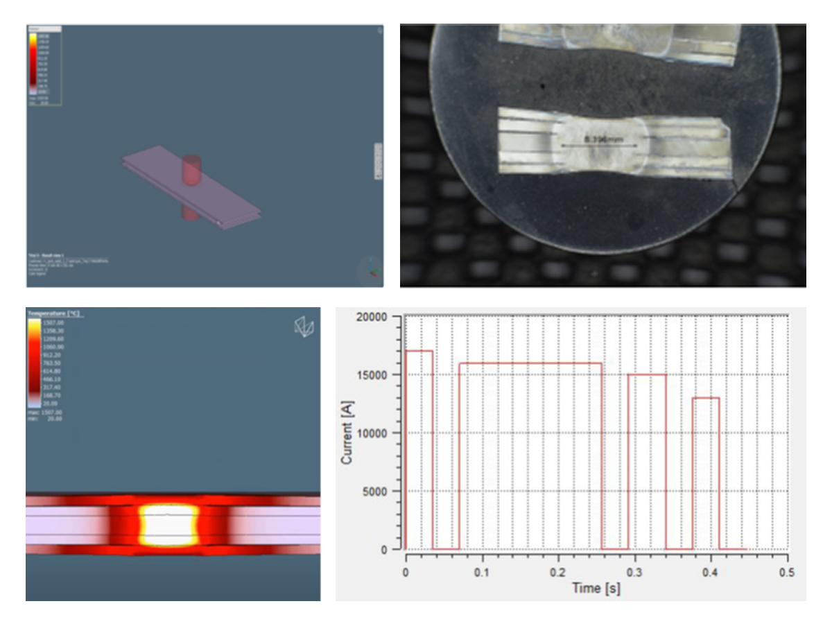
Figure 2. Example of simulation and experimental results showing acceptable 5T resistance spot weld (Meets AWS Automotive specifications)

Thanks is given to Menachem Kimchi, Associate Professor-Practice, Dept of Materials Science, Ohio State University and Technical Editor – Joining, AHSS Application Guidelines, for this article.
RSW of Dissimilar Steel
This article is the summary of a paper entitled, “HAZ Softening of RSW of 3T Dissimilar Steel Stack-up”, Y. Lu., et al.L-15
Electromechanical Model
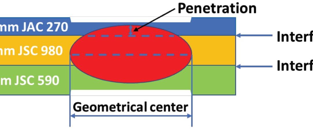
The study discusses the development of a 3D fully coupled thermo-electromechanical model for RSW of a three sheet (3T) stack-up of dissimilar steels. Figure 1 schematically shows the stack-up used in the study. The stack-up chosen is representative of the complex stack-ups used in BIW. Table 1 summarizes the nominal compositions of the three steels labeled in Figure 1.
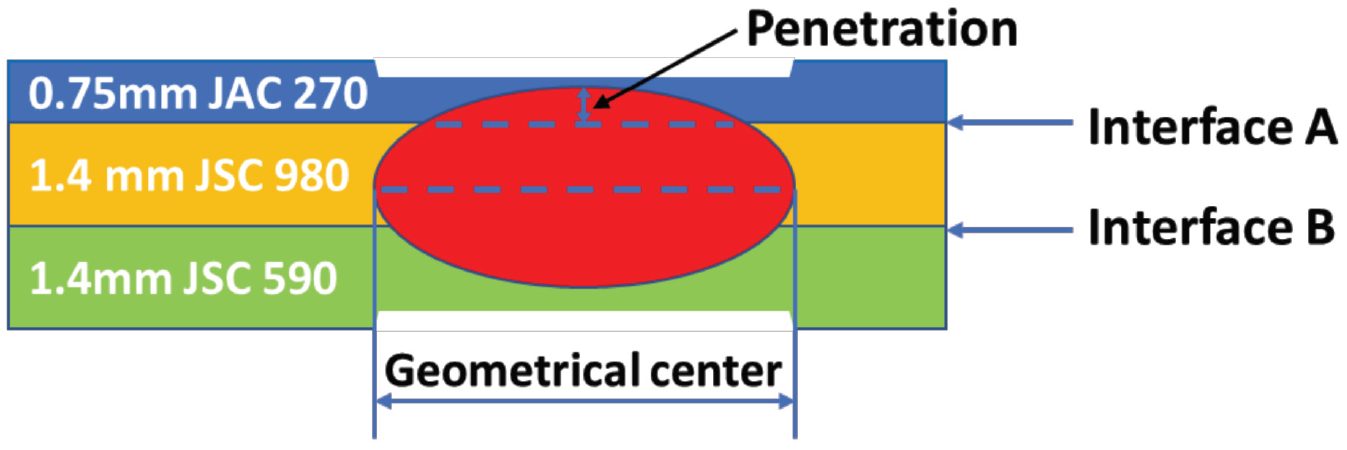
Figure 1: Schematics of the 3T stack-up of 0.75-mm-thick JAC 270/1.4-mm-thick JSC 980/1.4-mm-thick JSC 590 steels.L-15
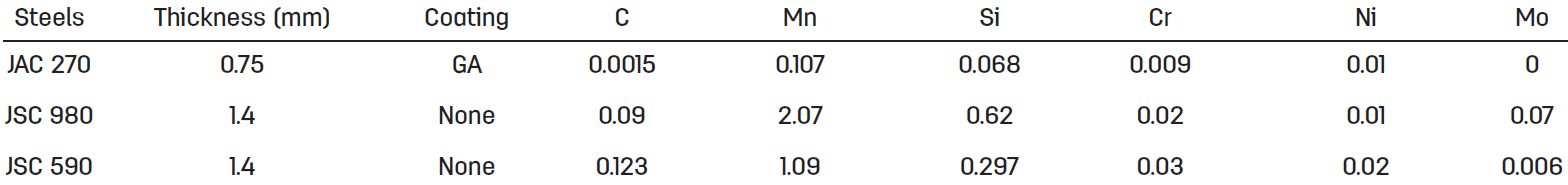
Table 1: Nominal Composition of Steels.L-15
JAC270 is a cold rolled Mild steel with a galvanneal coating having a minimum tensile strength of 270 MPa. JSC590 and JSC980 are bare cold rolled Dual Phase steels with a minimum tensile strength of 590 MPa and 980 MPa, respectively.
The electrodes used were CuZr dome-radius electrodes with a surface diameter of 6 mm. The welding parameters are listed in Table 2.
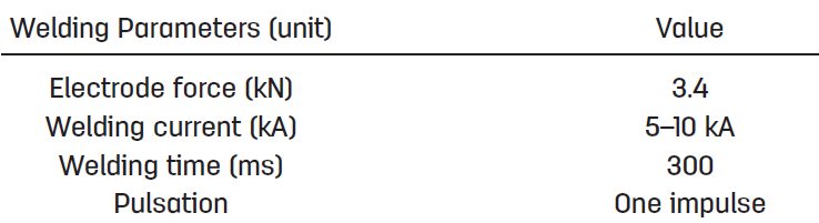
Table 2: Welding Parameters for Resistance Spot Welding of 3T Stack-Up of Steel Sheets.L-15
Figure 2 shows consistent nugget dimensions between simulation and experiment, supporting the validity of the RSW process model for 3T stack-up. The effect of welding current on nugget penetration into the thin sheet is similar to that on the nugget size. It increases rapidly at low welding current and saturates to 32% when the welding current is higher than 9 kA, as shown in Figure 2C.
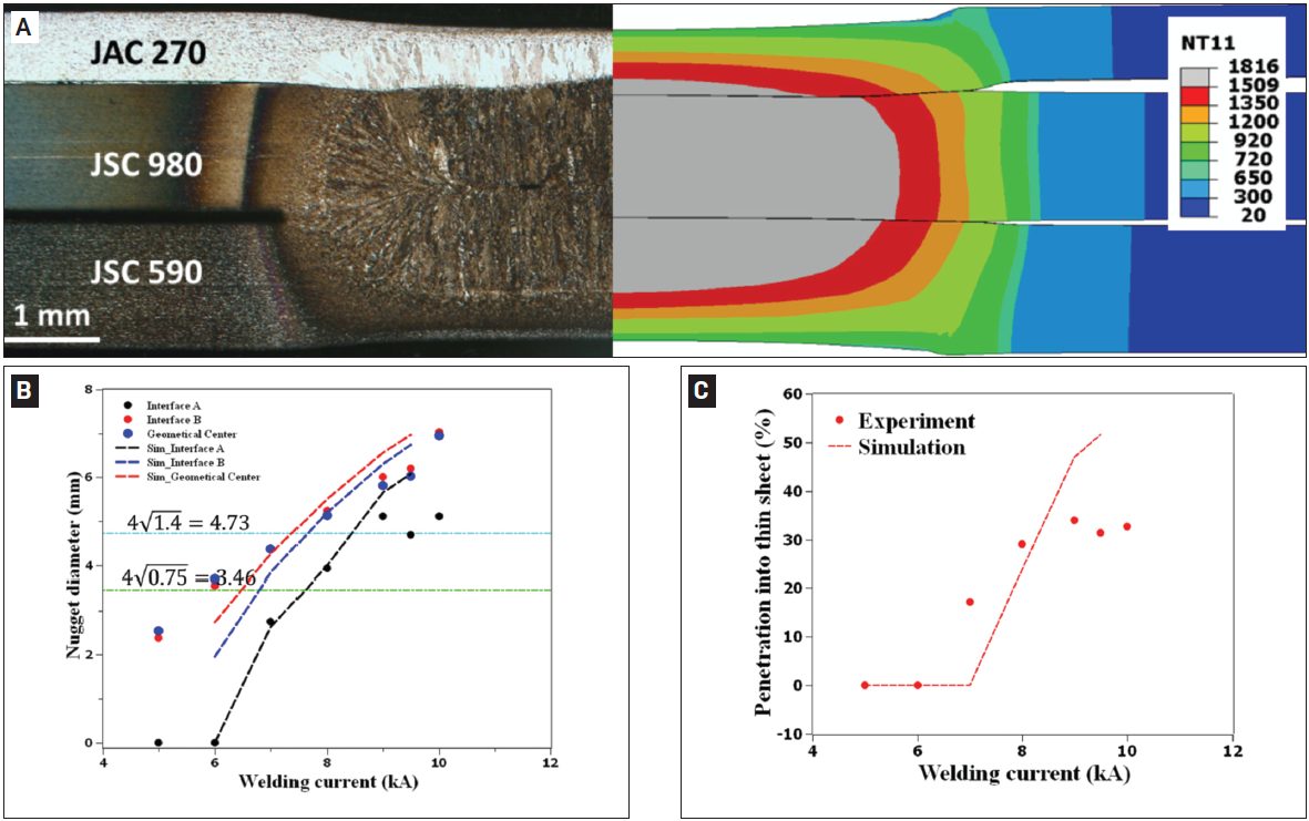
Figure 2: Comparison between experimental and simulated results: A) Nugget geometry at 8 kA; B) nugget diameters; C) nugget penetration into the thin sheet as a function of welding current. In Figure 2A, the simulated nugget geometry is represented by the distribution of peak temperature (in Celsius). The two horizontal lines in Figure 2B represent the minimal nugget diameter at Interfaces A and B calculated, according to AWS D8.1M: 2007, Specification for Automotive Weld Quality Resistance Spot Welding of Steel. Due to limited number of samples available for testing, the variability in nugget dimensions at each welding current was not measuredL-15.
The results for nugget formation during RSW of the 3T stack-up are show in Figures 3-5. Figure 2 shows that, at the start of welding, the contact pressure at interface A (thin/thick) has a higher peak and drops more quickly along the radial direction than that at interface B (thick/thick). Due to the more localized contact area (Figure 3), a high current density can be observed at interface A, as shown in Figure 4A. Additionally, due to the high current density at interface A, localized heating is generated at this interface, as shown in Figure 5A.
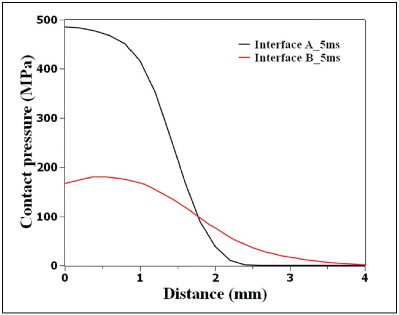
Figure 3: Calculated contact pressure distribution at interfaces A (thin/thick) and B (thick/thick) at a welding time of 5 ms, current of 8 kA, and electrode force of 3.4 L-15
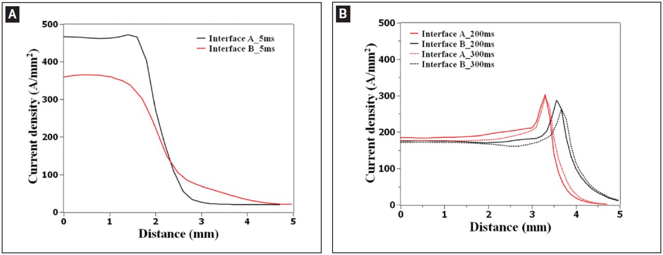
Figure 4: Calculated current density distribution at interfaces A (thin/thick) and B (thick/thick) at welding time of A — 5 ms; B — 200 and 300 ms.L-15
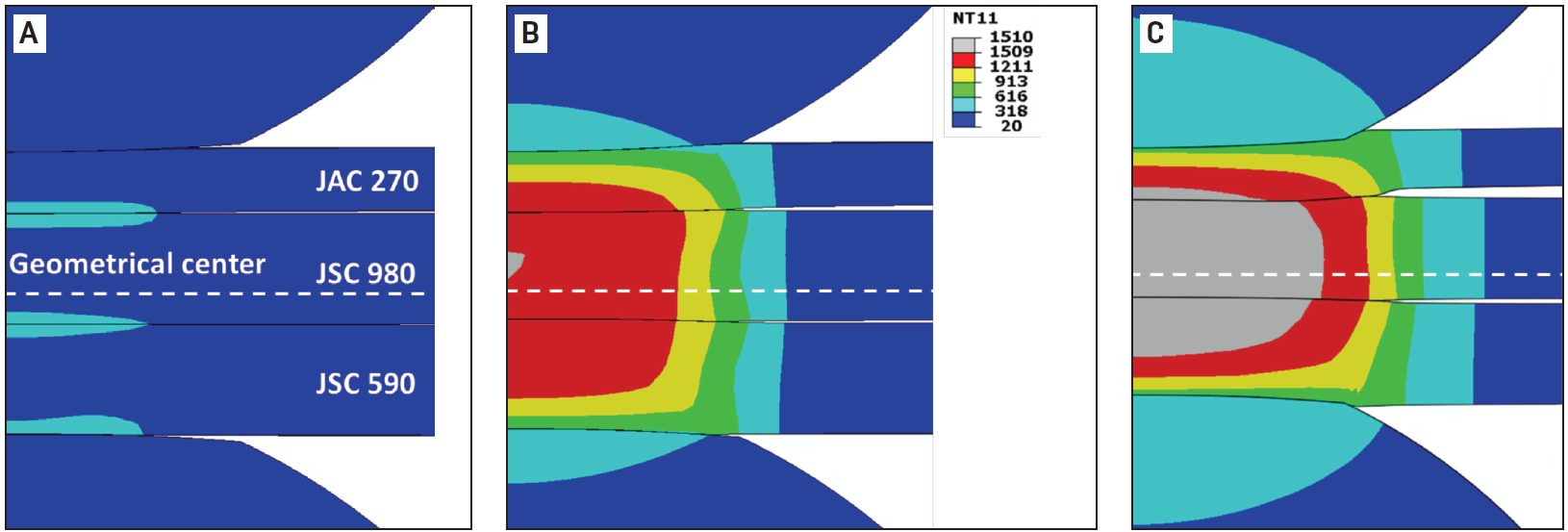
Figure 5: Temperature distribution during resistance spot welding of 3T stack-up at welding times of A) 5 ms; B) 102 ms; C) 300 ms. Welding current is 8 kA and electrode force is 3.4 kN. Calculated temperature is given in Celsius.L-15
As welding time increases, the contact area is expanded, resulting in a decrease of current density. The heat generation rate is shifted from interfaces to the bulk and the peak temperature occurs near the geometrical center of the stack-up.
Figure 6 illustrates that the predicted value corresponds well with the experimental data indicating a sound fitting to the isothermal tempering experimental data.
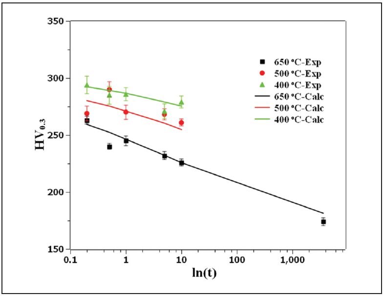
Figure 6: Comparison of the measured hardness with JMAK calculation showing the goodness of fit of the JSC 980 tempering kinetics parameters.L-15
Figure 7 shows the predicted hardness map of RSW 3T stack-up as well as the predicted and measured hardness profiles for JSC 980.
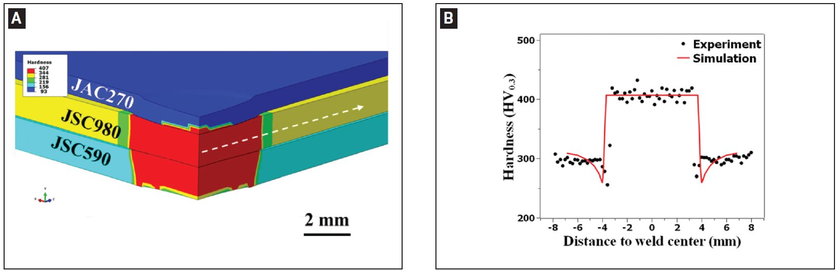
Figure 7: A) Predicted hardness map of resistance spot welded 3T stack-up; B) predicted and measured hardness profiles along the line marked in (A) for JSC 980.L-15
Manufacturing Issues
Spot Welding of Three Steel Sheets with Large Thickness Ratios
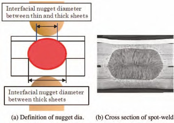
Car parts such as side panels are fabricated by spot welding three steel sheets together. When the outer steel sheet is a thin sheet of mild steel and the reinforcement steel sheets are thick sheets of HSS (that is, when there is a large thickness ratio between the sheets), it is often difficult to spot weld such sheets together. The term “thickness ratio” as used herein refers to the total thickness of the three steel sheets divided by the thickness of the thinnest steel sheet. Nuggets obtained by spot welding of three steel sheets are illustrated in Figure 1 (a). In the spot welding of three steel sheets with a large thickness ratio, it is difficult to form a nugget at the interface between thin and thick steel sheets, as shown in Figure 1 (b). The reason for this is that in spot welding, because of heat removal by the water-cooled electrode, the fusion progresses from the thickness center of the three steel sheets toward the outside, except for the heat generated by contact resistance at the steel sheet surfaces in the early stages of welding time. In addition, in view of the dimensional accuracy of actual members, it is necessary to set appropriate welding conditions when there is a gap between steel sheets. In practice, the proper welding current range is as shown in Figure 2. However, the welding current range is often narrower in one-step spot welding.
Figure 1: Three sheets spot welded.N-5
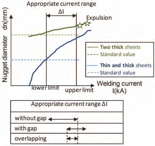
Figure 2: Weldability lobe of three sheets spot welded.
As a means of solving the above problem when there is no gap between the steel sheets, a method has been proposed in which the diameter of the electrode tip at the thin-sheet side is reduced and the welding force and current are varied during the welding time. In addition, a two- step pulsating current welding method (Figure 3) has been proposed in which neither the electrode diameter nor the welding force are changed. This method is described briefly below. Initially, during the first welding step, a relatively large welding current is passed to generate heat by using the contact resistance at the interface between the thin and thick steel sheets and that between the thick steel sheets. This method does not positively use the contact resistance that is effective when the electrode force is low. Since the method can be applied even under a high electrode force, it is particularly effective when there is a gap between the steel sheets to be welded together.
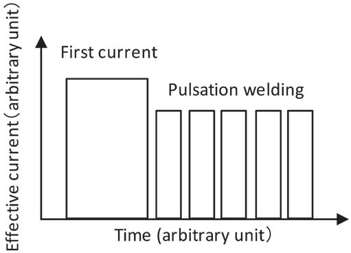
Figure 3: Welding current pattern.
An experiment was conducted by using the above technology. The materials used were a 0.6- mm-thick sheet of mild steel and two 1.6-mm-thick sheets of HSS (980 MPa class). Spacers 1.4-mm thick were inserted at intervals of 40 mm between the thin and thick steel sheets and between the thick steel sheets. A servomotor-driven, single-phase AC welder was used for the test. The electrode used was a Cr-Cu dome radius type with a 40-mm tip upper radius and 6-mm tip lower diameter. The welding force was 3.43 kN. To evaluate the diameter of fusion at the interface between the thin and thick sheets, which determines the proper current range, a chisel test was conducted at the interface and evaluated the plug diameter.
The test results are illustrated in Figure 4. The horizontal axis represents the first step welding current for one-step welding (welding time t1 = 18 cycles) and the second-step welding current for two-step welding (first welding time t1 = 18 cycles, second welding time t2 = 8 cycles) or pulsation welding [t1 = 18 cycles, t2 = (5-cycle heat/2-cycle cool) × 5]. For one- or two-step welding, the welding current range was less than 1 kA. Conversely, with pulsation, it was possible to secure a proper welding range of 3 kA or more (about 1.8 kA when there was no gap between the steel sheets).
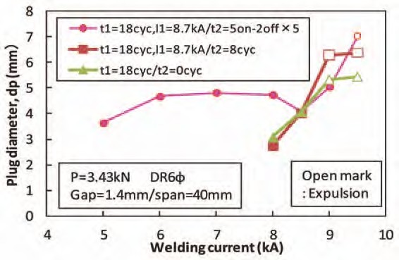
Figure 4: Current ranges for different welding current patterns.
In addition to the two-step pulsating current welding method (Figure 4 above), preheating the sheets at 20-25% of the normal current before beginning the impulses can be effective when joining three layers of extremely different thicknesses. Figure 5 shows a weld cross section using preheating prior to three impulses.
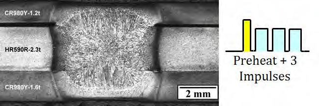
Figure 5: Cross section of three sheet spot weld including preheating prior to pulsations.C-6
Another solution to RSW three sheets is when the Fusion Zone (FZ) formation process is controlled by setting the welding current and welding force during welding in multiple steps; this is referred to as Intelligent Spot Welding. (ISW). Using this approach, nugget formation between a thin sheet and thick sheet becomes possible when reduced welding force is applied. In Step 1 of the welding process, a FZ is reliably formed between the thin sheet and thick sheet by applying conditions of low welding force, short welding time, and high current. In the subsequent Step 2, a FZ is formed between the two thick sheets by apply high welding force and a long welding time. The results are shown in Figure 6, in which welding is performed with the edge of three steel sheets positioned directly under the electrodes, and the behavior of FZ formation at the edge of the sheets was observed with a high-speed video camera. Condition (a) is welding under a constant welding force and condition (b) is ISW. In condition (a), a nugget was formed between the two thick sheets, but the nugget failed to grow to the thin sheet-thick sheet joint, and the two sheets were not welded. However, condition (b) shows that nuggets have formed between both the thin and thick sheet and between the two thick sheets. The optimal welding current range for Step 2 can be determined from nugget formation between the two thick sheets, resulting in a wide available current range equal to or greater than that in joint welding of two thick sheets.
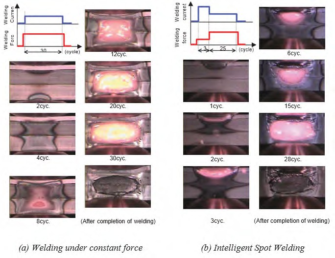
Figure 6: Results of observation of FZ formation phenomenon in RSW of three-sheet joint by high-speed video camera.J-1
Application of Spot Welding to Hollow Members
In spot welding of car bodies, the so-called direct spot welding (in which the welding current is passed while two or more steel sheets are pressed against each other) by the welding electrodes is used most commonly. However, for those parts with closed cross sections, it may become necessary to drill a working hole through which the electrodes for direct spot welding of the steel sheets can be passed. In this case, the decline in rigidity of the drilled part being compensated for by using a thicker steel sheet or providing a reinforcing member will inevitably increase the weight of the car body. Therefore, attempts were made to reduce the steel sheet thickness (weight) and secure the required stiffness simultaneously without drilling any hole in the steel sheets. Indirect spot welding was used, in which the steel sheets are pressed and welded by a couple of electrodes from one side at the same time. Because the steel sheets are pressed by electrodes from one side, the weld sinks and the area of contact between the steel sheets increases (the current density decreases) if an excessive force is applied, making it difficult to perform fusion welding. Conversely, if an excessively large current is applied, the local current density between the electrodes increases because of a shunt current, causing a crack or explosion.
Studies were made for various welding conditions for the combination of a hollow member with a 1.6-mm wall thickness and a sheet-formed member with a 0.7-mm thickness. By using an electrode with a specially designed tip and a DC power supply in combination, indirect spot welding could be performed of the above members without requiring any special pattern of conduction or pressing, even in the presence of a gap between the members or the presence of shunts (existing welding points). An example of the cross section of an indirect spot weld is illustrated in Figure 1, which clearly indicates that a sufficiently large nugget was formed.
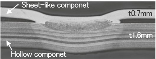
Figure 1: Cross section of indirect spot weld for hollow and sheet-like components.
For the indirect RSW with single-side access of the welding electrode, the variable controls of electrode force and current during welding were developed to promote the weld nugget formation. Experiments as well as numerical simulations were conducted to study the welding phenomena and optimize the welding process. It was verified that the nugget was stably formed with the developed process even when shunting was large. Figure 2 describes the effect of variable current and force on the promotion of weld nugget formation.
At the first stage with low welding current and high electrode force, the electric conduction with sufficient load at weld preheats the sheet, which promotes contacting area between the electrode and upper sheet and thus inhibits the expulsion from the surface. Meanwhile, contacting area between upper and lower sheets is also promoted forming the stable conduction path. Subsequently, at the second stage with high welding current and low electrode force, the nugget formation is effectively promoted with a heated region concentrated at the center in weld, avoiding the further penetration of welding electrode into the upper sheet and thus maintaining the current density.
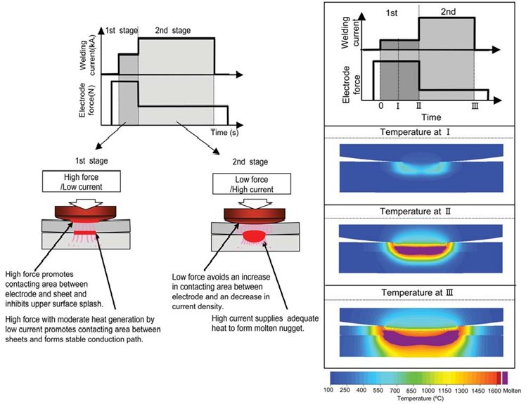
Figure 2: Concept of nugget formation process of variable current and force control for single-sided RSW.J-1
Back To Top