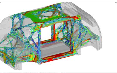
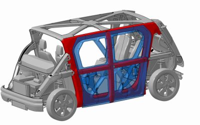
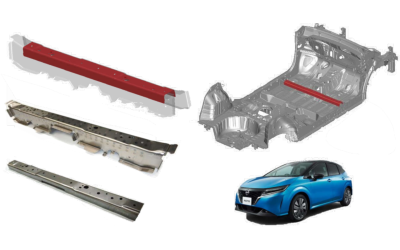
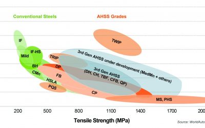
Servo Press Force and Energy Considerations When Working With AHSS

Servo Press Force and Energy Considerations When Working With AHSS

Advanced High-Strength Steel (AHSS) products have significantly different forming characteristics and these challenge conventional mechanical and hydraulic presses. Some examples include the dramatically higher strength of these new steels resulting in higher forming loads and increased springback. Also, higher contact pressures cause higher temperatures at the die-steel interface, requiring high performance lubricants and tool steel inserts with advanced coatings.

These and other challenges lead to issues with the precision of part formation and stamping line productivity. Using a servo-driven press is one approach to address the challenges of forming and cutting AHSS grades. Recent growth in the use of servo presses in the automotive manufacturing industry parallels the increased use of AHSS in the body structure of new automobiles. Click to read more about the Characteristics of Servo Presses and their Advantages.

Figure 1 shows the difference between the available motions of flywheel-driven mechanical presses verses servo driven mechanical presses. The slide motion of the servo press can be programmed for more parts per minute, decreased drawing speed to reduce quality errors, or dwelling or re-striking at bottom dead center to reduce springback.

Figure 2: Comparison of Press Signatures in Fixed Motion Mechanical Presses and Free-Motion Servo-Driven Presses.M-3

Figure 1: Comparison of Press Signatures in Fixed Motion Mechanical Presses and Free-Motion Servo-Driven Presses.M-3


Press Force and Press Energy

Categorizing both mechanical and hydraulic presses requires three different capacities or ratings – force, energy, and power. Historically, when making parts out of mild steel or even some HSLA steels, using the old rules-of-thumb to estimate forming loads was sufficient. Once the tonnage requirements and some processing requirements were known, stamping could occur in whichever press met those minimum tonnage and bed size requirements.

In these cases, press capacity (for example, 1000 kN) is a suitable number for the mechanical characteristics of a stamping press. Capacity, or tonnage rating, indicates the maximum force that the press can apply without damaging its components, like the machine frame, slide-adjusting mechanisms, pitman (connection rods) or main gear bushings.

A servo press transmits force (not energy) the same way as the equivalent conventional press (mechanical or hydraulic). However, the amount of force available throughout the stroke depends on whether the press is hydraulic or mechanically driven. Hydraulic presses can exert maximum force during the entire stroke as tonnage generation occurs via hydraulic fluid, pumps, and cylinders. Mechanical presses exert their maximum force at a specific distance above bottom dead center (BDC), usually defined at 0.5 inch. At increased distances above bottom dead center, the loss of mechanical advantage reduces the tonnage available for the press to apply. This phenomenon is known as de-rated tonnage, and it applies to conventional mechanical presses as well as servo-mechanical presses. Figure 2  shows a typical press-force curve for a 600-ton mechanical press. In this example, when the press is approximately 3 inches off BDC, the maximum tonnage available is only 250 tons – significantly less than the 600-ton rating.

Figure 5: The Press-Force curve shows the maximum tonnage a mechanical press can apply based on the position of the slide relative to the bottom dead center reference distance. This de-rated tonnage applies to both conventional mechanical presses as well as servo-mechanical presses.E-2

Figure 2: The Press-Force curve shows the maximum tonnage a mechanical press can apply based on the position of the slide relative to the bottom dead center reference distance. This de-rated tonnage applies to both conventional mechanical presses as well as servo-mechanical presses.E-2


Press energy reflects the ability to provide that force over a specified distance (draw depth) at a given cycle rate. Figure 3 shows a typical press-energy curve for the same 600-ton mechanical press. The energy available depends on the size and speed of the flywheel, as well as the size of the main drive motor. As the flywheel rotates faster, the amount of stored energy increases, reflected in the first portion of the curve. The cutting or forming process consumes energy, which the drive motor must replenish during the nonworking part of the stroke. At faster speeds, the motor has less time to restore the energy. If the energy cannot be restored in time, the press stalls. The graph illustrates how the available energy of the press diminishes to 25% of the rated capacity when accompanied by a speed reduction from 24 strokes per minute to 12 strokes per minute.

Figure 6: A representative press-energy curve for a 600 ton mechanical press. Reducing the stroke rate from 24 to 12 reduces available energy by 75%.E-2

Figure 3: A representative press-energy curve for a 600 ton mechanical press. Reducing the stroke rate from 24 to 12 reduces available energy by 75%.E-2


Case Study: Press Force and Press EnergyH-3

Predicting the press forces needed initially to form a part is known from a basic understanding of sheet metal forming. Different methods are available to calculate drawing force, ram force, slide force, or blankholder force. The press load signature is an output from most forming-process development simulation programs, as well as special press load monitors. The topic of press force predictions will be covered in this Blog in the months ahead.

Most structural components include design features to improve local stiffness. Typically, forming of the features requiring embossing processes occurs near the end of the stroke near Bottom Dead Center. Predicting forces needed for such a process is usually based on press shop experiences applicable to conventional steel grades. To generate comparable numbers for AHSS grades, forming process simulation is recommended.

In Citation H-3, stamping simulations evaluated the forming of a cross member having a hat-profile with an embossment formed at the end of the stroke (Figure 4). The study simulated press forces and press energy involved for drawing and embossing a channel section from four steel grades approximately 1.5 mm thick: mild steel, HSLA 250/350, HSLA 350/450, and DP 350/600. Figures 5A and 5B clearly show that the embossing phase rather than the drawing phase dominates the total force and energy requirements, even though the punch travel for embossing is only a fraction of the drawing depth.

Figure 10: Cross section of a component having a longitudinal embossment to improve local stiffness.H-3

Figure 4: Cross section of a component having a longitudinal embossment to improve local stiffness.H-3


Figure 11: Embossing requires significantly more (A) force and (B) energy than drawing, even though the punch travel in the embossing stage is much smaller.H-3

Figure 5: Embossing requires significantly more (A) force and (B) energy than drawing, even though the punch travel in the embossing stage is much smaller.H-3


Figures 6 and 7 highlight the press energy requirements, showing the greater energy required for higher strength steels. The embossment starts to form at a punch displacement of 85 mm, indicated by the three dots in Figure 6. The last increment of punch travel to 98 mm requires significantly higher energy, as shown in Figure 7. Note that compared with mild steel, the dual phase steel grade requires significantly more energy to form the part to home with the 98 mm travel.

Figure 12: Energy needed to form the component increases for higher strength steel grades. Forming the embossment begins at 85 mm of punch travel, indicated by the 3 dots.H-3

Figure 6: Energy needed to form the component increases for higher strength steel grades. Forming the embossment begins at 85 mm of punch travel, indicated by the 3 dots.H-3


Figure 13: Additional energy required to form the embossment increases for higher strength steel grades.H-3

Figure 7: Additional energy required to form the embossment increases for higher strength steel grades.H-3


It is not only embossments that require substantially more force and energy at the end of the stroke. Stake beads for springback control engage late in the stroke to provide sidewall stretch. Depending on the design of the forming process, the steel into which the stake beads engage may have passed through conventional draw beads for metal flow control, and therefore are work-hardened to an even higher strength. This leads to greater requirements for die closing force and energy. Certain draw-bead geometries which demand different closing conditions around the periphery of the stamping also may influence closing force and energy requirements.

A more detailed Press Requirements article contains additional information and case studies.  Read it here >>>


A New Global Formability Diagram

A New Global Formability Diagram

Bubble chart. Banana diagram. Steel strength ductility diagram—it’s been called a lot of things over the years. But the 2021 chart shown in Figure 1 is the subject of hundreds of requests for use we receive from engineers and students all over the world and appears in thousands of presentations and papers. Because of that, we periodically update it to make sure it reflects the most current picture of both commercially available, as well as emerging steel grades. In this blog, we are providing our updated GFD for download as well as definitions of steel classifications, as agreed to by our member companies.

Figure 2: The Global Formability Diagram comparing strength and elongation of current and emerging steel grades.

Figure 1: The 2021 Global Formability Diagram comparing strength and elongation of current and emerging steel grades.


Steel Classifications

There are different ways to classify automotive steels. One is a metallurgical designation providing some process information. Common designations include lower-strength steels (interstitial-free and mild steels); conventional high strength steels, such as bake hardenable and high-strength, low-alloy steels (HSLA); and Advanced High-Strength Steels (AHSS) such as dual phase and transformation-induced plasticity steels. Additional higher strength steels include press hardening steels and steels designed for unique applications that have improved edge stretch and stretch bending characteristics.

A second classification method important to part designers is strength of the steel. This document will use the general terms HSLA and AHSS to designate all higher strength steels. The principal difference between conventional HSLA steels and AHSS is their microstructure. Conventional HSLA steels are single-phase ferritic steels with a potential for some pearlite in C-Mn steels.

AHSS are primarily steels with a multiphase microstructure containing one or more phases other than ferrite, pearlite, or cementite – for example martensite, bainite, austenite, and/or retained austenite in quantities sufficient to produce unique mechanical properties. Some types of AHSS have a higher strain hardening capacity resulting in a strength-ductility balance superior to conventional steels. Other types have ultra-high yield and tensile strengths and show a bake hardening behavior.

What are 3rd Gen Steels?

Third Generation, or 3rd Gen, AHSS builds on the previously developed 1st Gen AHSS (DP, TRIP, CP, MS, and PHS) and 2nd Gen AHSS (TWIP), with global commercialization starting around 2020. Third Gen AHSS are multi-phase steels engineered to develop enhanced formability as measured in tensile, sheared edge, and/or bending tests. Typically, these steels rely on retained austenite in a bainite or martensite matrix and potentially some amount of ferrite and/or precipitates, all in specific proportions and distributions, to develop these enhanced properties.

Graphical Presentation

Generally, elongation (a measure of ductility) decreases as strength increases. Plotting elongation on the vertical axis and strength on the horizontal axis leads to a graph starting in the upper left (high elongation, lower strength) and progressing to the lower right (lower elongation, higher strength). When considering conventional steels and the first generation of advanced high strength steels, this shape led to the colloquial description of calling this the banana diagram.

With the continued development of advanced steel options, it is no longer appropriate to describe the plethora of options as being in the shape of a banana. Instead, with new grades filling the upper right portion of Figure 1, perhaps it is more accurate to describe this as the football diagram as the options now start to fall into the shape of an American or Rugby Football. Officially, it is known as the steel Global Formability Diagram.

Even this approach has its limitations. Elongation is only one measure of ductility. Other ductility parameters are increasingly important with AHSS grades, such as hole expansion and bendability. There are several other approaches that have been proposed by experts around the world. Have a look at our Defining Steels article, from which this article was drawn, to learn more about them. You will also find within Defining Steels a detailed explanation of the nomenclature used throughout the Guidelines to define steels. If you have questions, please use the Comments tool below or on the Defining Steels page.

Download the GFD

Because of its popularity, we provide high resolution image files of the GFD here for your download and use. Please source it “Courtesy of WorldAutoSteel” in your papers and presentations. We are happy for you to use it.  If you require our signed permission, please write us at steel@worldautosteel.org. We’ll respond quickly.

* The Guidelines use the general terms HSLA and AHSS to designate all higher strength steels.

Additive Manufacturing

Additive Manufacturing

Additive Manufacturing (AM) has been associated with the future of manufacturing since its inception. While it does hold several advantages in complex geometries and low-volume production, modern AM systems have yet to make significant in-roads with direct-print parts in industries like automotive manufacturing which are characterized by large volumes of relatively large metal parts. With typical volumes of 1,000+ vehicles per line per day, the required throughput of automotive factory lines outstrips what is available in current AM systems. Further, the large volume of parts allows for rapid amortization of capital equipment such as tools, dies, and stamping presses, circumventing one of the primary advantages of AM: reduced per-piece cost. However, if the focus is shifted from direct-print parts to manufacturing the supporting infrastructure, tools and dies, the economic benefits are regained. Using AM to manufacture forming tools for Advanced High-Strength Steels (AHSS) and Press Hardened Steels (PHS) brings the opportunity for reduced tooling lead-time, reduced tooling cost, and optimization of the tools for weight, strength, and thermal management.

Metal AM: Application in Traditional Forming

While AM enables the flexible production of tools with lead-time reduction and minimal economic impactsG-35, W-29, the production cost for the metal AM tools is significantly higher compared to polymer AM tools and, in some cases, metal tools manufactured by conventional methods. However, cost of the AM tools can be mitigated through topology optimization.A-61 With topology optimization, parts with freeform geometry can be designed that are optimized against a specific objective, for example weight, strength, or stiffness. By reducing overall tool material while maintaining strength, build time on the AM system can be reduced, thereby lowering tool cost.

Potential applications of metal AM forming tools are in prototype construction or small series production, e.g. holders, flanges or medium-size adapters and reinforcing plates.S-74 AM methods have also been utilized for insertion of beads or other geometries for reinforcing/increasing the stiffness of tools.L-36 Cost typically prevents metal AM tools from being used in low-volume cold forming applications where the main tool body is printed, however, high wear components and insert applications have demonstrated significant lead-time savings over traditional manufacturing methods.L-36 Metal AM may be considered in cold forming applications where lead-time is at a premium and cost concerns are secondary.

However, in instances where complex internal structures are required, the increased cost of metal AM is outstripped by the benefits it can provide over conventionally manufactured tools. One such example is a metal AM tool for white goods that utilizes high performance stainless steel for the forming surface and less expensive mild steel for the underlying structure. The resulting die, Figure 6, was constructed from less material, reducing overall machining time required to create the finish die surface.P-25

Figure 6: Metal AM die under construction and after nitriding. [REFERENCE 39]

Figure 6: Metal AM die under construction and after nitriding.P-25

Metal AM: Application in Hot Stamping

An important advantage of hot forming is that it requires low-forming loads and enables forming parts with high strength and minimal springback. However, the high temperatures required to form the material and the precise cooling required to ensure desirable component properties necessitate advanced tooling designs.

Bulk materials used for fabricating hot stamping dies require special properties. The tool material must exhibit high tensile strength, hardness, good corrosion resistance, a low thermal expansion coefficient, and high thermal conductivity.N-19 Traditionally, casting and machining are used to manufacture hot stamping tools, however, in recent years AM has gained significant traction due to the design freedom that it offers, especially when it comes to fabricating tools with conformal cooling channels. Reducing porosity is one of the primary remaining challenges to maximizing mechanical properties and achieving good build quality in AM components. Conventionally manufactured hot tool steels demonstrate properties of at least 1300 MPa tensile strength, 50 HRC hardness, 18 J of impact toughness and 22 W/mK of thermal conductivity. Selected AM materials should demonstrate at least these properties in order to be considered a reliable alternative.

Hot stamp tooling with conformal cooling channels has been demonstrated with both Directed Energy Deposition (DED) and and Powder-Bed Fusion (PBF) AM processes. With DED processes, it is possible to attain minimum channel diameters as low as 3 mm and a minimum wall thicknesses of 2 mm. Unlike drilling straight holes, as done with traditional tool manufacturing, it is possible to design and fabricate complex cooling channels inside the die that results in homogeneous temperature distribution within the tool and the stamped parts. The improved temperature distribution leads to lower cycle times in hot stamping and subsequent improvement in process efficiency, reducing overall production costs. DED also has been combined with subtractive processes to create a hybrid manufacturing process.C-21 One example includes hot stamping dies manufactured by machining and additively building inserts with conformal cooling ducts.M-35 As a result, the additively manufactured channels cooled six times faster than the conventional drilled channels. In another example, manufactured injection molds with conformal cooling ducts by combining direct metal rapid tooling and machining.A-62

PBF processes are also used to integrate conformal cooling channels into forging dies and hot stamping tools. Regardless of the AM method, development of the internal network channels can be aided by topology optimization, a tool that offers great flexibility in designing non-intuitive, novel, and complex parts with high performance at reduced material cost.G-36 In addition to optimizing for mechanical objectives, topology optimization can also be defined such that it designs products considering performance criteria across multiple domains such as thermal and mechanical. Such multi-objective topology optimization is a powerful tool in designing metal AM tooling that takes advantage of the optimized thermal and mechanical performance made possible through AM processes.

This is an excerpt of a full Guidelines article entitled, “Additive Manufacturing for Sheet Metal Forming Tools,” which is based on a project conducted in partnership between Honda Development & Manufacturing of America, LLC and The Ohio State University. This excerpt focuses on metal AM in traditional forming and hot stamping, while the full article surveys the use of polymer and metal AM for forming tools and discusses the benefits and challenges with respect to their use in manufacturing AHSS and PHS sheet metal components. Be sure to read the full article for the much more detail.


Many thanks are given the team who contributed the Additive Manufacturing article, from which this blog was excerpted.

Ryan Hahnlen Ryan Hahnlen, Honda Development & Manufacturing of America, LLC, Raymond, OH
Ben Hoffman, Honda Development & Manufacturing of America, LLC, Raymond, OH
Madhura Athale, Integrated Systems Engineering Department at Ohio State University, Columbus, OH
Taejoon Park, Integrated Systems Engineering Department at Ohio State University, Columbus, OH
Farhang Pourboghrat, Integrated Systems Engineering Department at Ohio State University, Columbus, OH Farhang Pourboghrat, Integrated Systems Engineering Department at Ohio State University, Columbus, OH


Vision for Industry 4.0 in Sheet Metal Forming

Vision for Industry 4.0 in Sheet Metal Forming

There is interest in the sheet metal industry on how to adopt Industry 4.0 into their legacy forming practices to significantly improve productivity and product quality. Figure 1 illustrates four important variables influencing part quality: material properties, die friction response, elastic deflection of the tool, and press dynamic characteristics. These variables are usually difficult to measure or track during the production runs. When these variables significantly influence the part quality and the scrap rate increases, the operators manually adjust the forming press parameters (speed and pressure), lubricant amount, and tooling setup. However, these manual adjustments are not always possible or effective and can be costly for the increased part complexity.

Figure 2: Important variables influencing the stamping quality.H-35

Figure 1: Important variables influencing the stamping quality.H-35


The ultimate vision for Industry 4.0 in sheet metal forming is an autonomous forming process with maximum process efficiency and minimum scrap rate. This is very similar to the full self-driving (FSD) vision of the electric vehicle today. This will be valuable for the automotive industry that has to process large production volumes with various steel grades.

For example, normal variations of the incoming material properties for Advanced High-Strength Steel (AHSS) may have a significant effect on part quality associated with necking, wrinkling, and cracking, which in turn drastically increases the production cost. This variation of the incoming material properties increases uncertainty in sheet metal forming by making consistent quality more challenging to achieve, thereby increasing the overall manufacturing cost. A nondestructive evaluation (NDE) can be a useful tool to measure incoming material properties.

There are several types of NDE sensors. Most of the sensors need further development or are not suitable for production applications. However, some of the NDE sensors, such as the eddy current tools, laser triangulation sensors equipment, and equipment developed by Fraunhofer IZFP called 3MA (micromagnetic, multiparametric microstructure, and stress analysis), have already been applied to a few limited production applications. These sensors can be used to provide data during production to select the optimal parameters. They also can be used to obtain material properties for finite element model (FEM) analysis. Studies in deep drawing of a kitchen sink production used a laser triangulation sensor to measure the sheet thickness and an eddy-current sensor to measure the yield strengthtensile strengthuniform elongationelongation to break, and grain size of the incoming material. The material data is used as an input for simulations to generate the metamodels to determine the process window, and it is used as an input for the feed-forward control during the process.K-27

Figure 2 shows how NDE tools are used for feed-forward controls and cameras for feedback control to determine the optimum press setting on sink forming production.

Figure 4: Process control for sheet metal forming of kitchen sink production.H-36

Figure 2: Process control for sheet metal forming of kitchen sink production.H-36


Another study proposed the use of Fraunhofer’s 3MA equipment to determine the mechanical properties of incoming blanks for a sheet forming process. The 3MA sensor correlates the magnetic properties of the material with the mechanical properties and calibrates the system with the procedure outlined in Figure 3. The study showed a good correlation between the measurements from the sensor and the tensile testing results; however, the sensor should be calibrated for each material. Also, the study proposed to use a machine-learning algorithm instead of a feed-forward control to predict the most effective parameters during the drawing process.K-28

Figure 5: Calibration procedure for 3MA sensors.K-28

Figure 3: Calibration procedure for 3MA sensors.K-28


Technologies associated with Industry 4.0 have a natural fit with AHSS. The advanced slide motion capabilities of servo presses combined with active binder force control can be paired with stamping tonnage and edge location measurements from every hit to create closed-loop feedback control. With press hardening steels (PHS), vision sensors and thermal cameras can be used for controlling the press machine and transfer system.

Have a look at the Dr. Kim’s detailed article on Industry 4.0 for more examples of NDE sensors, as well as information on applying Industry 4.0 to forming process controls.


Thanks are given to Hyunok Kim, Ph.D., Director of EWI Forming Center, who contributed this article. Thanks are given to Hyunok Kim, Ph.D., Director of EWI Forming Center, who contributed this article.


Welcome to the All New AHSS Application Guidelines!

Welcome to the All New AHSS Application Guidelines!

The leading source for technical best practices on the forming and joining of Advanced High-Strength Steels (AHSS) for vehicle manufacture is released today by WorldAutoSteel, the automotive group of the World Steel Association. The AHSS Application Guidelines Version 7.0 is now online at ahssinsights.org in a searchable database, allowing users to pinpoint information critical to successful use of these amazingly capable steels. WorldAutoSteel members make these Guidelines freely available for use to the world’s automotive community.

“More and more automakers are turning to AHSS to balance the needs for crashworthiness, lighter weight and lower emissions, while still manufacturing cars that are affordable,” says George Coates, Technical Director, WorldAutoSteel. “The AHSS Application Guidelines provides critical knowledge that will help users adapt their manufacturing environment to these evolving steels and understand processes and technologies that lead to efficient vehicle structures.” AHSS constitute as much as 70 percent of the steel content in vehicle structures today, according to automaker reports.

New grades of steel that are profiled in Version 7.0 show dramatically increased strength while achieving breakthrough formability, enabling applications and geometries that previously were not attainable.

“Steel’s low primary production emissions, now coupled with efficient fabrication methods, as well as a strong global recycling and reuse infrastructure all create a solid foundation upon which to pursue vehicle carbon neutrality,” notes Cees ten Broek, Director, WorldAutoSteel. “These Guidelines contain knowledge gleaned from global research and experience, including significant investment of our members who are the designers and manufacturers of these steels.”

Editors and Authors Dr. Daniel Schaeffler, President Engineering Quality Solutions, Inc., for Metallurgy and Forming, and Menachem Kimchi, M.Sc., Assistant Professor – Practice, Materials Science and Engineering, Ohio State University, have drawn from the insights of WorldAutoSteel members companies, automotive OEMs and suppliers, and leading steel researchers and application experts. Together with their own research and field experience, the technical team have refreshed existing data and added a wealth of new information in this updated version.

The new database includes a host of new resources for automotive engineers, design and manufacturing personnel and students of automotive manufacturing, including:

  • Hundreds of pages of searchable articles that include nearly 1,000 citations of original technical research papers, providing a rich library for study.
  • Search tools and related posts fueled by thousands of industry-specific keywords that enable users to drill down to the information they need.
  • Information on the metallurgy and mechanics of AHSS grades.
  • An explanation of 3rd Gen AHSS and what makes these grades unique.
  • A primer on Press Hardened Steels, one of the most popular AHSS grades in today’s automotive structures.
  • Summaries of new research in resistance spot welding for joining AHSS of multiple grades and thicknesses.
  • New information on modelling resistance spot welding.
  • An expanded solid state welding section.
  • New information on RSW joining of dissimilar steels as well as dissimilar materials.
  • Articles written by subject-matter experts and product manufacturers.
  • Integration of the popular AHSS Insights technical blog.

The new online format enables consistent annual updates as new mastery of AHSS’s unique microstructures is gained, new technology and grades are developed, and data is gathered.  Be sure to subscribe to receive regular updates and blogs that represent a world of experience as the database evolves.

You’re right where you need to be to start exploring the database.  Click Tutorials from the top menu to get a tour on how the site works so you can make the best of your experience.  Come back often–we’re available 24/7 anywhere in the world, no download needed!

Steel Structures for Autonomous Vehicles

Steel Structures for Autonomous Vehicles

The WorldAutoSteel Steel E-Motive program has been moving along now for nearly a year, and we’d like to share an update with you, our engineering colleagues, on some of the design decisions we’re facing. If you recall, the Steel E-Motive program is designing vehicle concepts for Mobility as a Service (MaaS), characterized by autonomous, electric, ride sharing vehicles.


Some Background

We partnered with Ricardo headquartered in the UK to conduct the design and engineering of the vehicles. Ricardo was selected for their well-known reputation for innovation, their demonstrated knowledge of vehicle powertrains and electrification and their commitment to sustainable transportation. Our steel members subject matter experts work with Ricardo via various teams and working groups to push the envelope of steel applications. And given our pandemic, all of this currently occurs via virtual meetings.

Targeting technologies available for deployment in 2030+, we are considering the impacts to vehicle manufacturers, fleet operators and the ride hailing customer, as MaaS inevitably leads to an increase in demand for vehicle sharing, rental models and ride-hailing services over the next decade. We can represent these requirements as shown in Figure 1. On the left you’ll see broad needs for the critical stakeholders including space efficiency, flexibility and total cost of ownership. Those requirements translate into 12 key considerations for the mobility service provider, shown on the right, aimed at delivering value to customers and a sustainable and profitable business model. These considerations then require innovative design, engineering and materials applications.

Figure 1: MaaS key attributes and functions.

Figure 1: MaaS key attributes and functions.


There are four main phases to Steel E-Motive (Figure 2). Phase 0 was a 3-month pre-study, beginning 30 June 2020, to review and confirm vehicle targets, essentially defining the foundations, goals and approach for the project. On 1 October 2020, we entered the Phase 1 concept engineering, exploring the challenges and steel solutions for Level 5 autonomous vehicles. Essentially, we are designing the body structure in this Phase, utilizing CAE tools to guide us. Phase 2 focusses on further refinement and optimization of the selected body concept, and ensuring the design is fully validated as there will be no working prototypes or hardware produced in the project. Phase 3 will be the roll out and dissemination activities, although you will see from the Steel E-Motive website and blogs that we are continually releasing material throughout the project.

Figure 2: Project timing and key activities.

Figure 2: Project timing and key activities.


We’ll be disclosing detailed targets and specifications later in the program, but Figure 3 provides overall dimensions. Battery electric will be the primary propulsion with competitive range. There are two variants: urban for inner city and shorter journeys, and an extra-urban variant for longer city-to-city (or city-to-airport) journeys. With Level 5 autonomy, there are no direct driver interfaces such as the steering column and pedals. You can see from the Figure that the vehicles are fairly compact. The urban variant sits between a European B and C segment in size. The extra-urban vehicle has a stretched wheelbase and can accommodate up to six passengers and a greater luggage capacity.

Figure 3: SEM vehicle technical specification and dimensions – base vehicle geometry.

Figure 3: SEM vehicle technical specification and dimensions – base vehicle geometry.


The vehicles will be engineered and purposed for global application; therefore, we are considering the major global crash and safety standards and load cases. High volume production is targeted, greater than 250,000 units per annum, and a hypothetical production date of 2030, which influences the steel grades and fabrication processes considered. Third Generation AHSS (3rd Gen AHSS) and press-hardened steels continue to evolve with higher strength and improved formability. Between these innovative product capabilities, we are addressing the challenges associated with Mobility as a Service and tackling geometries that otherwise would have been difficult to produce.

To further assist in the design and manufacture of efficient vehicle structures, there are many new manufacturing processes, such as roll forming and hot stamping, that help fabricate these stronger materials effectively, while often doubling material use efficiency. Figure 4 provides a list of technologies that will be considered for Steel E-Motive.

Figure 4: Steel technologies included in SEM’s portfolio.

Figure 4: Steel technologies included in SEM’s portfolio.


With the portfolio of steel product and manufacturing processes already available and the addition of those forecasted for future commercial availability, we are expecting innovations that will be a roadmap for future mobility vehicle manufacturers.

Our end goal is to demonstrate multi-purpose opportunities for the vehicles via a modular architecture enabled by the application of innovative steel solutions. These solutions will help Steel E-Motive achieve a low environment footprint measured over the vehicle Life Cycle, and meet global crash standards while delivering the lowest Total Cost of Ownership (TCO).

To reach our goal of demonstrating steel innovation in this program, we are using a theoretical frameworkH-2 as a guide, shown in Figure 5, considering innovation at an architectural level. That is, using body structure load paths shown in the vertical axis, and modular innovation for the major body components such as battery enclosure, side/crash rails, shown in the horizontal axis. Combining innovation levels and types of the two axes should enable us to demonstrate radical innovation in Steel E-Motive.

Figure 5: Steel E-Motive explores and demonstrates steel innovation. Exploring “modular” and “architectural” innovations for 2030 production.

Figure 5: Steel E-Motive explores and demonstrates steel innovation. Exploring “modular” and “architectural” innovations for 2030 production.

Design Challenges

Figure 6 reveals an early or basic Steel E-Motive architecture. You can see that Level 5 autonomy creates both design freedoms that allow new occupant seating positions, while also creating challenges for short front and rear overhangs. We have an open pod-type structure with large door apertures for enhanced occupant ergonomics.

Figure 6: Challenges and opportunities of Level 5 autonomous MaaS battery electric vehicle.

Figure 6: Challenges and opportunities of Level 5 autonomous MaaS battery electric vehicle.


Passenger comfort is key for MaaS vehicles. The open pod structure may give challenges with the air cavity mode coupling with structural modes. With occupants in different positions, we have different NVH source-path-receiver paths to consider. The larger door aperture gives us an inherent deficiency in overall body structure stiffness, for which we need to compensate. As with any BEV, the mass of the battery suspended on the lower structure may reduce body modes to frequencies that interact with other vehicle systems such as suspension modes. With a lot of emphasis on lower structure crash zones and battery protection, we may encounter some lower frequency upper body modes (such as lozenging), especially as we are targeting low overall body mass. These NVH risks and challenges are being addressed by taking a modal mapping approach, utilizing steel’s inherent high structural stiffness properties and undertaking thorough NVH simulation throughout the engineering phases.

Level 5 autonomy removes the requirements for driver vision and obscuration, but we do need to acknowledge passenger comfort issues, such as motion sickness. Consequently the designs consider a good level of outward visibility. However, we now have the freedom to place structure where we could not previously. We are using 3D topology FEA tools to help determine the optimum placement of structure in the body, and we have allowed the tool the freedom to place structure in the front and rear glazed areas. In the Figure 7 example, the software is recommending some structural members across the front windscreen, and further analysis shows that this has the potential to give us an overall Body-In-White weight saving as the load paths are more evenly distributed.

Figure 7: Level 5 autonomy removes the driver vision and obscuration requirements—an opportunity for new solutions.

Figure 7: Level 5 autonomy removes the driver vision and obscuration requirements—an opportunity for new solutions.


To summarize the Steel E-Motive engineering activities, we are currently exploring the numerous challenges and opportunities that Level 5 autonomous BEVs provide us. We are in the concept phase, investigating both the overall body structure layout and load paths, as well as developing components and modules utilizing the unique properties of steel.

We expect to complete the program with full virtual concepts by December 2022. Our plans are to unveil more and more of the design concepts over the months to come, and we’ll be using virtual reality and other tools to communicate the concepts’ engineering. We invite you to subscribe at the website to receive all the news that will be coming out of the program, including more technical details as they become available. You can do that at www.steelemotive.world. We’re excited to share Steel E-Motive innovations in the future!