WorldAutoSteel is focused on advancing steel's advantages in the automotive, autonomous vehicle, and future mobility industries. To encourage careers in engineering, we are committed to engaging with future engineers at post-secondary education organizations around...
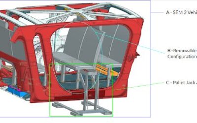
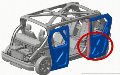
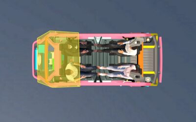
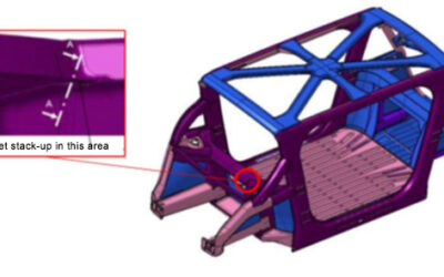
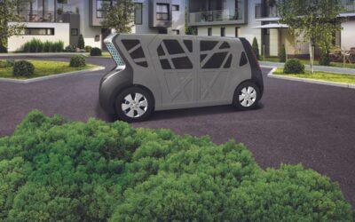
Meeting the Challenges of Autonomous Vehicles: A Steel E-Motive Student Engagement to Adapt SEM2 from People Mover to Commercial Delivery Vehicle
read more