Advanced High-Strength Steel (AHSS) products have significantly different forming characteristics and these challenge conventional mechanical and hydraulic presses. Some examples include the dramatically higher strength of these new steels resulting in higher forming loads and increased springback. Also, higher contact pressures cause higher temperatures at the die-steel interface, requiring high performance lubricants and tool steel inserts with advanced coatings.
These and other challenges lead to issues with the precision of part formation and stamping line productivity. Using a servo-driven press is one approach to address the challenges of forming and cutting AHSS grades. Recent growth in the use of servo presses in the automotive manufacturing industry parallels the increased use of AHSS in the body structure of new automobiles. Click to read more about the Characteristics of Servo Presses and their Advantages.
Figure 1 shows the difference between the available motions of flywheel-driven mechanical presses verses servo driven mechanical presses. The slide motion of the servo press can be programmed for more parts per minute, decreased drawing speed to reduce quality errors, or dwelling or re-striking at bottom dead center to reduce springback.

Figure 1: Comparison of Press Signatures in Fixed Motion Mechanical Presses and Free-Motion Servo-Driven Presses.M-3
Press Force and Press Energy
Categorizing both mechanical and hydraulic presses requires three different capacities or ratings – force, energy, and power. Historically, when making parts out of mild steel or even some HSLA steels, using the old rules-of-thumb to estimate forming loads was sufficient. Once the tonnage requirements and some processing requirements were known, stamping could occur in whichever press met those minimum tonnage and bed size requirements.
In these cases, press capacity (for example, 1000 kN) is a suitable number for the mechanical characteristics of a stamping press. Capacity, or tonnage rating, indicates the maximum force that the press can apply without damaging its components, like the machine frame, slide-adjusting mechanisms, pitman (connection rods) or main gear bushings.
A servo press transmits force (not energy) the same way as the equivalent conventional press (mechanical or hydraulic). However, the amount of force available throughout the stroke depends on whether the press is hydraulic or mechanically driven. Hydraulic presses can exert maximum force during the entire stroke as tonnage generation occurs via hydraulic fluid, pumps, and cylinders. Mechanical presses exert their maximum force at a specific distance above bottom dead center (BDC), usually defined at 0.5 inch. At increased distances above bottom dead center, the loss of mechanical advantage reduces the tonnage available for the press to apply. This phenomenon is known as de-rated tonnage, and it applies to conventional mechanical presses as well as servo-mechanical presses. Figure 2 shows a typical press-force curve for a 600-ton mechanical press. In this example, when the press is approximately 3 inches off BDC, the maximum tonnage available is only 250 tons – significantly less than the 600-ton rating.

Figure 2: The Press-Force curve shows the maximum tonnage a mechanical press can apply based on the position of the slide relative to the bottom dead center reference distance. This de-rated tonnage applies to both conventional mechanical presses as well as servo-mechanical presses.E-2
Press energy reflects the ability to provide that force over a specified distance (draw depth) at a given cycle rate. Figure 3 shows a typical press-energy curve for the same 600-ton mechanical press. The energy available depends on the size and speed of the flywheel, as well as the size of the main drive motor. As the flywheel rotates faster, the amount of stored energy increases, reflected in the first portion of the curve. The cutting or forming process consumes energy, which the drive motor must replenish during the nonworking part of the stroke. At faster speeds, the motor has less time to restore the energy. If the energy cannot be restored in time, the press stalls. The graph illustrates how the available energy of the press diminishes to 25% of the rated capacity when accompanied by a speed reduction from 24 strokes per minute to 12 strokes per minute.

Figure 3: A representative press-energy curve for a 600 ton mechanical press. Reducing the stroke rate from 24 to 12 reduces available energy by 75%.E-2
Case Study: Press Force and Press EnergyH-3
Predicting the press forces needed initially to form a part is known from a basic understanding of sheet metal forming. Different methods are available to calculate drawing force, ram force, slide force, or blankholder force. The press load signature is an output from most forming-process development simulation programs, as well as special press load monitors. The topic of press force predictions will be covered in this Blog in the months ahead.
Most structural components include design features to improve local stiffness. Typically, forming of the features requiring embossing processes occurs near the end of the stroke near Bottom Dead Center. Predicting forces needed for such a process is usually based on press shop experiences applicable to conventional steel grades. To generate comparable numbers for AHSS grades, forming process simulation is recommended.
In Citation H-3, stamping simulations evaluated the forming of a cross member having a hat-profile with an embossment formed at the end of the stroke (Figure 4). The study simulated press forces and press energy involved for drawing and embossing a channel section from four steel grades approximately 1.5 mm thick: mild steel, HSLA 250/350, HSLA 350/450, and DP 350/600. Figures 5A and 5B clearly show that the embossing phase rather than the drawing phase dominates the total force and energy requirements, even though the punch travel for embossing is only a fraction of the drawing depth.

Figure 4: Cross section of a component having a longitudinal embossment to improve local stiffness.H-3
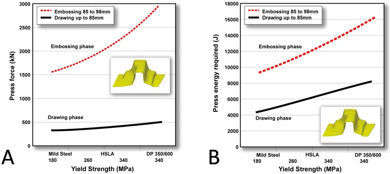
Figure 5: Embossing requires significantly more (A) force and (B) energy than drawing, even though the punch travel in the embossing stage is much smaller.H-3
Figures 6 and 7 highlight the press energy requirements, showing the greater energy required for higher strength steels. The embossment starts to form at a punch displacement of 85 mm, indicated by the three dots in Figure 6. The last increment of punch travel to 98 mm requires significantly higher energy, as shown in Figure 7. Note that compared with mild steel, the dual phase steel grade requires significantly more energy to form the part to home with the 98 mm travel.

Figure 6: Energy needed to form the component increases for higher strength steel grades. Forming the embossment begins at 85 mm of punch travel, indicated by the 3 dots.H-3

Figure 7: Additional energy required to form the embossment increases for higher strength steel grades.H-3
It is not only embossments that require substantially more force and energy at the end of the stroke. Stake beads for springback control engage late in the stroke to provide sidewall stretch. Depending on the design of the forming process, the steel into which the stake beads engage may have passed through conventional draw beads for metal flow control, and therefore are work-hardened to an even higher strength. This leads to greater requirements for die closing force and energy. Certain draw-bead geometries which demand different closing conditions around the periphery of the stamping also may influence closing force and energy requirements.
A more detailed Press Requirements article contains additional information and case studies. Read it here >>>