Tensile testing is one of the most basic formability characterization methods available. Results from tensile testing are a key input into metal forming simulations, but if the right information isn’t included, the simulation will not accurately reflect material behavior. Metal forming simulation is particularly beneficial on the value-added parts made from advanced high strength steels, since accurate simulations allow for optimal processing with minimal recuts … at least when the right information is used as inputs.
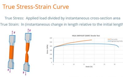
Tensile Testing: Engineering Stress-Strain Curves vs. True Stress-Strain Curves
read more