H-69
Citation:
H-69: P. Hein and J. Wilsius, “Status and Innovation Trends in Hot Stamping of USIBOR 1500 P,” steel research international, vol. 79, pp. 85-91, 2008.
H-69: P. Hein and J. Wilsius, “Status and Innovation Trends in Hot Stamping of USIBOR 1500 P,” steel research international, vol. 79, pp. 85-91, 2008.
P-5. M. Pfestorf and T. Laumann, “Potenziale verzinkter warm umgeformter Stähle,” in Tagungsband zum 3. Erlanger Workshop Warmblechumformung, 2008.
Liquid Metal Embrittlement (LME) during Resistance Spot Welding (RSW) can cause cracks when welding advanced high strength steels. Recent advances in steel metallurgy, resistance spot welding processing and accompanying simulation tools have substantially improved the way that LME can be handled in industrial practice. This article gives a brief overview of easy measures to implement when LME might potentially occur during production.
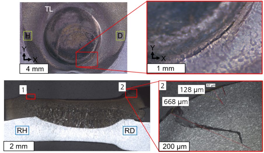
During resistance spot welding of zinc-coated advanced high strength steels (AHSS) liquid metal embrittlement -related cracking may be observed. Since LME is often associated with a reduction of steel’s mechanical properties, it is desired to control its occurrence during production. An exemplary LME crack, forced with increased weld heat and deliberate electrode misalignment, is shown below.
Figure 1: A typical LME crack created under laboratory conditions by deliberately increasing the welding time and introducing 5° electrode tilt
Over the past several years, LME has been a a focus in welding research. It is now well-understood to the degree that it can be predicted and avoided with easy measures. Below is an overview of four key steps to address the potential of LME during automotive production.
Over the past decade, steel producers have released AHSS with improved chemical compositions, helping to significantly reduce the occurrence of LME iIt is beneficial to talk with steel suppliers and ask about their latest AHSS grades, as these are likely far less sensitive to LME than previously tested grades. A recent study commissioned by WorldAutoSteel demonstrated that all five chosen material stack-ups from current production data did not show any LME even under exacerbated conditions. Only by choosing an especially difficult material stack-up could LME be forced to appear at all to conduct the study.
WorldAutoSteel has published two studies on liquid metal embrittlement: One focused on lab conditions and the second on real-life stamped components. These studies provide an overview of all aspects of LME and how to manage and avoid LME issues.
To investigate LME in-house, it’s critical to establish a testing protocol that forces the cracks to appear and allows for comparison of different steels, stack-ups and welding parameters. as there There is currently no industry-wide agreed-upon testing standard.
Still, there is a good selection of well-documented procedures to choose from. The easiest procedure is to increase the welding time until cracks start to appear – keep in mind that you need to remove the zinc coating before you can observe any cracks on the surface.
Other methods are based on so-called “Gleeble testing” or on deliberately introducing imperfections like tilted electrodes or large gaps into the welds. As you establish a testing procedure in your lab, you can use it to evaluate LME occurrence in the stack-ups that you want to implement into body-in-whites.
Suitable measures should always be adapted to the specific use case. Generally, the most effective measures for LME prevention or mitigation are:
These measures can be implemented in the planning stage and in an ongoing production environment to increase the LME-free process windows.
While Liquid Metal Embrittlement may present a challenge when welding AHSS, it’s no longer an unpredictable threat. Thanks to advancements in steel development, welding techniques, and testing methods, manufacturers have the tools they need to reliably mitigate LME during production.
Staying informed, working closely with steel suppliers, implementing smart testing protocols, and applying targeted welding strategies can help automakers maintain both strength and quality in AHSS joints. With this proactive approach, LME doesn’t have to stand in the way of innovation in automotive manufacturing.
Download the Phase 2 LME Report
Download the Phase 1 LME Report
Fraunhofer IPK simulation site
 |
Thanks go to Dr.-Ing Max Biegler, Group Lead, Joining & Coating Technology at Fraunhofer Institute for Production Systems and Design Technology IPK |
Metal forming simulation is particularly beneficial on the value-added parts made from advanced high strength steels, since accurate simulations allow for optimal processing with minimal recuts … at least when the right information is used as inputs.
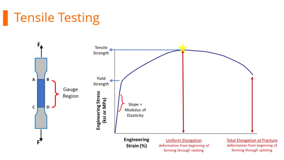
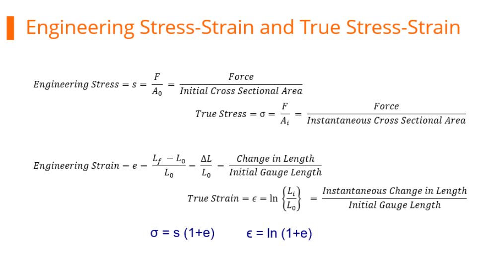
During tensile testing, a standard sample shape called a dogbone is pulled in tension. Load and displacement are recorded, and which are then converted to a stress-strain curve. Strength is defined as load divided by cross-sectional area. Exactly when the cross-sectional area is measured during the test influences the results.
Before starting the pull, it’s easiest to measure the width and thickness of the test sample.
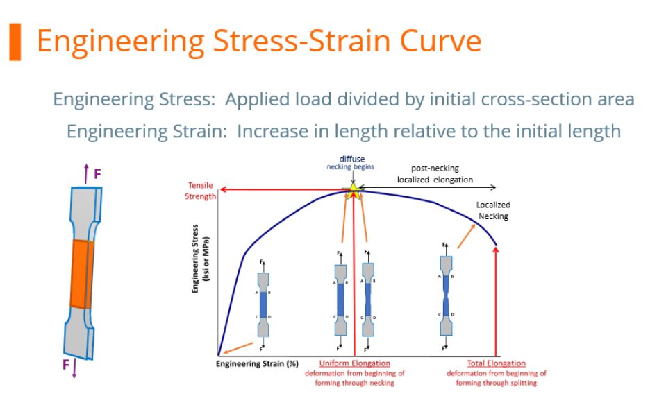
At any load, the engineering stress is the load divided by this initial cross-sectional area. Engineering stress reaches a maximum at the Tensile Strength, which occurs at an engineering strain equal to Uniform Elongation. After that point, engineering stress decreases with increasing strain, progressing until the sample fractures.
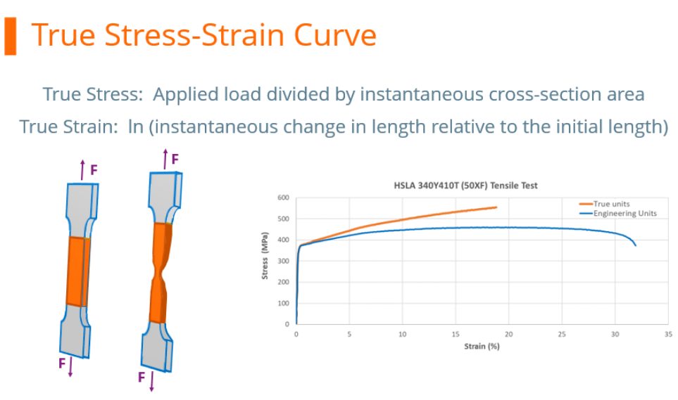
However, metals get stronger with deformation through a process known as strain hardening or work hardening. As a tensile test progresses, additional load must be applied to achieve further deformation, even after the “ultimate” tensile strength is reached. Understanding true stress and true strain helps to address the need for additional load after the peak strength is reached.
During the tensile test, the width and thickness shrink as the length of the test sample increases. Although these dimensional changes are not considered when determining the engineering stress, they are of primary importance when determining true stress. At any load, the true stress is the load divided by the cross-sectional area at that instant.
The true stress – true strain curve gives an accurate view of the stress-strain relationship, one where the stress is not dropping after exceeding the tensile strength stress level.
True stress is determined by dividing the tensile load by the instantaneous area.
True stress-strain curves obtained from tensile bars are valid only through uniform elongation due to the effects of necking and the associated strain state on the calculations. Inaccuracies are introduced if the true stress-true strain curve is extrapolated beyond uniform strain, and as such a different test is needed. Biaxial bulge testing has been used to determine stress-strain curves beyond uniform elongation. Optical measuring systems based on the principles of Digital Image Correlation (DIC) are used to measure strains. The method by which this test is performed is covered in ISO 16808.
Stress-strain curves and associated parameters historically were based on engineering units, since starting dimensions are easily measured and incorporated into the calculations. These are the values you see on certified metal properties, also called metal cert sheets that you get with your steel shipments.
True stress and true strain provide a much better representation of how the material behaves as it is being deformed, which explains its use in computer forming and crash simulations.
It’s much more challenging to get accurate dimensional measurements once the test has started unless there are multiple loops of the operator stopping the test, remeasuring, then restarting the pull. This is not a practical approach.
Fortunately, there are equations that relate engineering units to true units. Conventional stress-strain curves generated in engineering units can be converted to true units for inclusion in simulation software packages.
As the industry moves to more value-added stampings, metal forming simulation is done on nearly every part. The value-added nature of parts made from advanced high strength steels requires best practices be used throughout – otherwise the results from simulation drift further away from matching reality, leading to longer development times and costly recuts.

Danny Schaeffler is the Metallurgy and Forming Technical Editor of the AHSS Applications Guidelines available from WorldAutoSteel. He is founder and President of Engineering Quality Solutions (EQS). Danny wrote the monthly “Science of Forming” and “Metal Matters” column for Metalforming Magazine, and provides seminars on sheet metal formability for Auto/Steel Partnership and the Precision Metalforming Association. He has written for Stamping Journal and The Fabricator, and has lectured at FabTech. Danny is passionate about training new and experienced employees at manufacturing companies about how sheet metal properties impact their forming success.

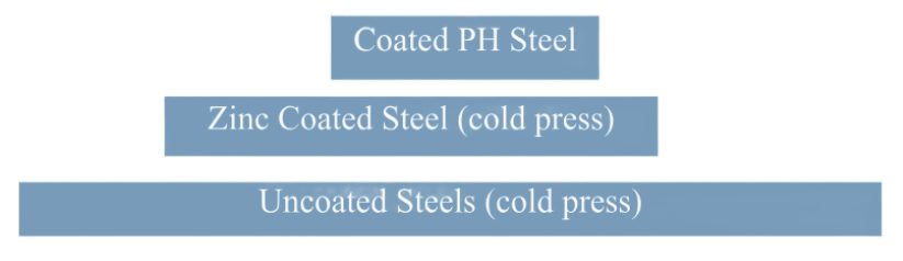
The discussions relative to cold stamping are applicable to any forming operation occurring at room temperature such as roll forming, hydroforming, or conventional stamping. Similarly, hot stamping refers to any set of operations using Press Hardening Steels (or Press Quenched Steels), including those that are roll formed or fluid formed.
Automakers contemplating whether a part is cold stamped or hot formed must consider numerous factors. This blog covers some important considerations related to welding these materials for automotive applications. Most important is the discussion on Resistance Spot Welding (RSW) as it is the dominating process in automotive manufacturing.
Specific welding parameters need to be developed for each combination of material type and thickness. In general, the Hot Press (HP) steels require more demanding process conditions. One important factor is electrode force which should be higher for the HP steel than for cold press type steel of the same thickness. The actual recommended force will depend on the strength level, and the thickness of the steel. Of course, this will affect the welding machine/welding gun force capability requirement.
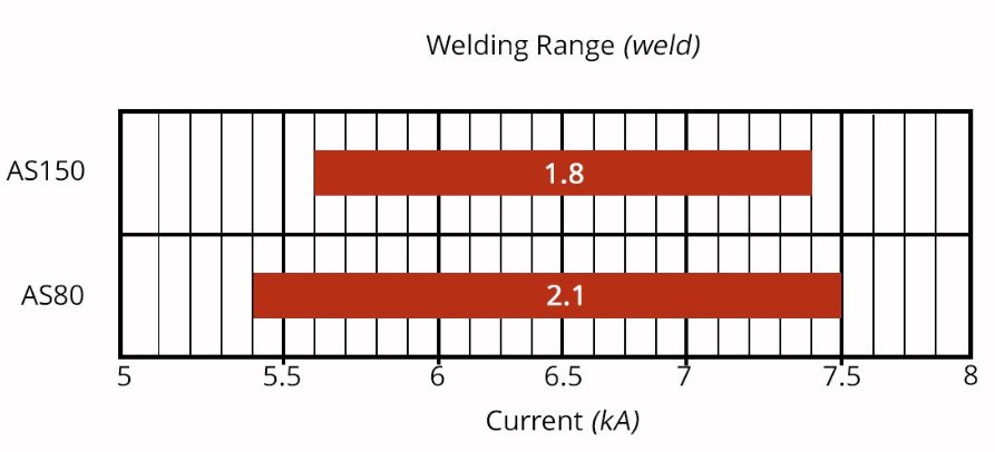
Another important variable is the welding current level and even more important is the current range at which acceptable welds can be made. The current range is weldability measurement, and the best indicator of the welding process robustness in the manufacturing environment and sometime called proceed window. Note the relative range of current for different steel types. A smaller process window may require more frequent weld quality evaluation such as for weld size.
Relative Current Range (process windows) for Different Steel Types
In all cases of resistance spot welding coated steels, it is imperative to move the coating away from the weld area during and in the beginning of the weld cycle to allow a steel-to-steel weld to occur. The combination of welding current, weld time and electrode force are responsible for this coating displacement.
For all the coated steels, the ability of the coating to flow is a function of the coating type and properties, such as electrical resistivity and melting point, as well as the coating thickness.
An example of cross sectioned spot welds made on Hot Press Steel with Aluminum -Silicon coating is shown below. It shows two coating thicknesses and the displaced coating at the periphery of weld. This figure also shows the difference in current range for the different coating thickness. The thicker coating shows a smaller current range. In addition, the Al-Si coating has a much higher melting point than the zinc coatings on the cold stamped steels, making it more difficult to displace from the weld area.
Hot Press Steel with Aluminum -Silicon
Cold-formable, coated, Advance High Strength Steels such as the 3rd Generation Advanced High Strength Steels are being widely used in automotive applications. One welding issue these materials encounter is the increased hardness in the weld area, that sometime results in brittle fracture of the weld.
Another issue is their sensitivity to Liquid Metal Embrittlement (LME) cracking. These two issues are discussed in detail on the WorldAutoSteel AHSS Guidelines website and our recently released Phase 2 Report on LME.
The most effective solution for the issues described above is using current pulsation during the welding cycle. A schematic description is shown below.
The pulsation allows much better control of the heat generation and the weld nugget development. The pulsation variables include the number of pulses (typically 2-4), the current level and time for each pulse, and the cool time between the pulses.
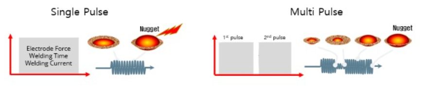
In summery, pulsation (and sometime current upslope) in Resistance Spot Welding proved to be beneficial for the following applications:

Thanks is given to Menachem Kimchi, Associate Professor-Practice, Dept of Materials Science, Ohio State University and Technical Editor – Joining, AHSS Application Guidelines, for this article.