Press Hardening Steel Grades: Unlocking Strength Through Innovation
You’ll find most of this content as part of our page on Press Hardening Steel Grades, but this month, we want to highlight it in our AHSS Insights blog. Thanks to Eren Billur, Ph.D., President, Billur Metal Form, for providing this information.
What Are Press Hardening Steel Grades and How Are They Made?
Press hardening is a special hot forming process, where the part is quenched in a forming die to receive its high hardness. It has been used in the automotive industry for over 40 years now.
The most common press hardening steel (PHS) is 22MnB5, a low carbon steel with Manganese-Boron alloying. Since it achieves a typical tensile strength of 1500 MPa after heat treatment, this material is mostly named as PHS1500 or CR1500T-MB (Cold Rolled, 1500 MPa typical Tensile strength, Manganese-Boron alloyed).B-14, V-19
The Direct Press Hardening Steel Process
The direct press hardening process involves heating the blanks over 900°C (1650°F) in an industrial furnace. The blanks are then removed from the furnace and quickly transferred to a forming die. The formed parts are not removed immediately. Instead, they are kept under force in a water-cooled tool set for quenching. With a 22MnB5 steel, the quenched part typically reaches 1500 MPa tensile strength. B-14
Coatings and Early Process Enhancements
Over the years, the first improvement on the 22MnB5 material was the application of an aluminum-silicon coating around early 2000’s. The addition of the coating did not affect its strength or elongation but improved the process as it eliminated scale formation during forming and quenching. AlSi coating however limited the process to the aforementioned direct process.B-14
Zinc Coatings and the Indirect Process
Some OEMs, especially in Europe, wanted to use Zn-based coatings for corrosion protection. The typical 22MnB5 is available with hot-dip galvanized (GI) and galvannealed (GA) coatings. Liquid metal embrittlement (LME) with Zn-based coatings is avoided with an indirect press hardening process. Forming is done at ambient temperatures, with the part subsequently heated and quenched in a press tool. These materials and techniques have been available since 2008.P-5
Figure 1 summarizes the most common 22MnB5 grades and coatings before and after the press hardening process.
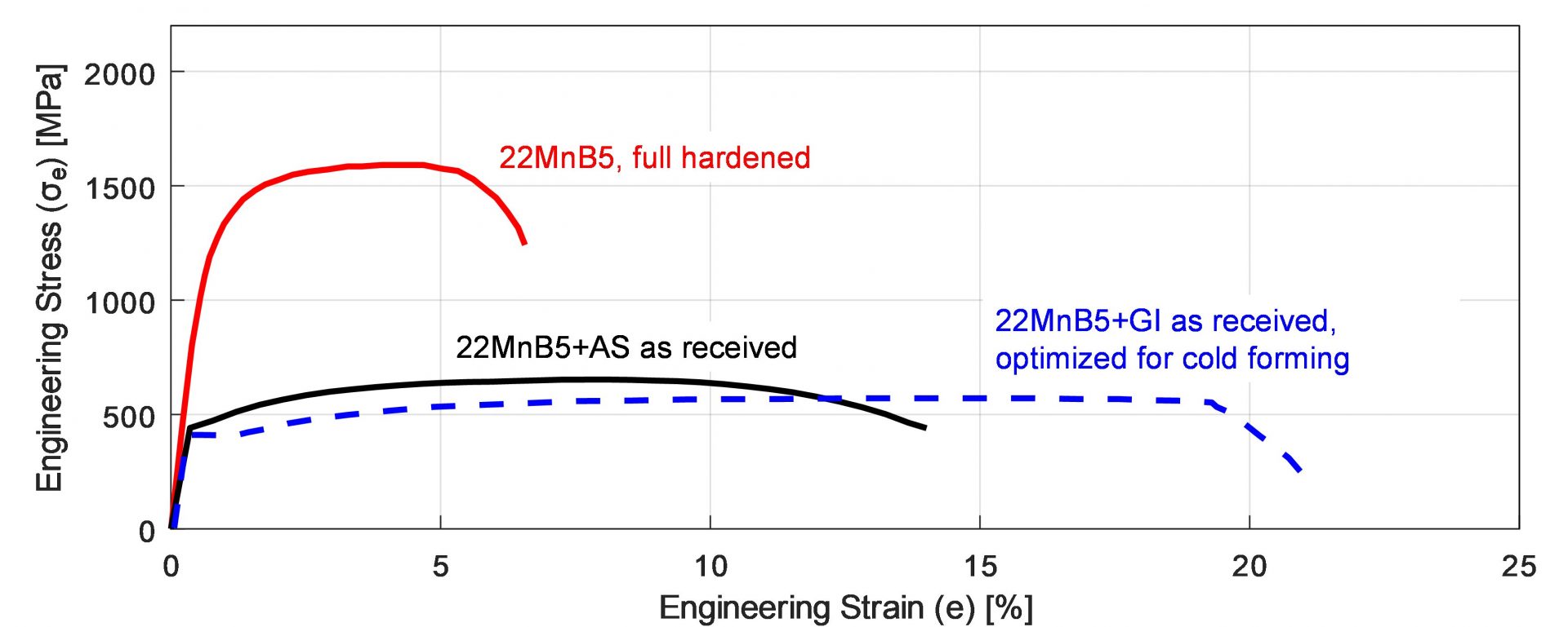
Figure 1: 22MnB5 before and after the hot stamping and quenching cycle. The incoming material is similar to HSLA 380 or DP600 and can be cold formed if needed. After hot stamping, typical tensile strength is around 1500 MPa (re-created after: B-18, O-8, U-9).
Measuring Performance: VDA Standards
In 2010, German Association of the Automotive Industry (VDA) developed a new bending test (238-100) to evaluate energy absorbing capacity of PHS and PQS grades.V-4 This test gave a “bending angle” measurement, which replaced – to some extent – the use of “total elongation” value for energy absorbing calculations.
PHS1800 and Beyond
In 2011, a Japanese steel maker developed the first 1800 MPa (typical) tensile strength material. The material was AlSi coated with a modified, higher carbon, 30MnB5 chemistry and Nb alloying.H-33 One Japanese OEM applied the material in their bumper beams. The higher strength allowed using 1.4 mm thick PHS1800 material, instead of 1.6 mm PHS1500.M-28
Tailored Solutions for Specific Applications
A German OEM designed a B-pillar with a PHS1500 upper section, laser welded to a lower section formed from HSLA 340LA (340 MPa yield strength) steel for improved energy absorption.S-13 It was later found that typical HSLA steels not designed for hot stamping process may show significant variation in mechanical properties depending on the cooling rate.D-22
The Rise of Press Quenched Steels (PQS)
Steel companies subsequently developed “Press Quenched Steels” (PQS) which are also HSLA but have been specifically modified to achieve consistent material properties at varying cooling rates.H-69 PQS grades are not hardenable, even after hot stamping and quenching cycle.
These steels were not used in the automotive industry until 2014, and have been commercially available since that time.L-29 These can be named as PQS450 and PQS550 (named after minimum tensile strength) or CR500T-LA and CR600T-LA (named after typical tensile strength, LA stands for Low Alloy).
Expanding Options: Pre-Cooled Steels
In 2015, a steel company in Europe developed 20MnB8 with GI coating. Chemistry with slightly lower carbon and higher manganese allowed forming to be done at lower temperatures. The company developed a new process route where the heated blank is first pre-cooled to around 500°C (930°F) and then formed and quenched – solving any LME concerns. The grade’s mechanical properties are nearly identical to 22MnB5 after quenching.K-21 Thus, it may be called PHS1500, but to differentiate the material, they are typically named CR1500T-MB-PS (PS stands for Pre-cooled Stamping).V-9
Expanding Options: Composite Steels
In 2016, two different composite steels were developed for hot stamping. These are 3-layers, hot rolled cladded grades with PQS on the outer skin and PHS1500 in the core. These were 1200 and 1400 MPa tensile strength level grades, with significantly improved bendability. There is only a commercial name for this material. To avoid using those names, the grades may be referred to as PHS1200 Sandwich and PHS1400 Sandwich.L-68
Improving Formability and Weldability
Around 2016, steel makers started developing another PHS grade which has 1000-1200 MPa tensile strength after quenching. The grade had almost similar elongation with PHS1500 (almost 5%), but higher bendability (75° vs. 50°). These grades also have lower metallurgical notch effects when spot welded. The material may be named CR1100T-MB.V-9
Multi-Step and Air-Hardening Innovations
In 2019, a Japanese steel company developed “air-hardening” 22MnSiB9-5 alloy with GA coating. After hot forming and quenching, the material had mechanical properties almost equivalent to 22MnB5. Thus, this material can also be named as PHS1500. Since the material is air-hardenable, meaning that it hardens even at very low cooling rates, it can be hot formed in a multi-station servo-mechanical-transfer press [16]. The technique is then named as “multi-step hot forming”, with the grade referred to as CR1500T-MB-MS (the last MS stands for Multi-Step).V-9
Ultra High Strength and the VDA Naming System
Since 2020, steel companies rolled out 1900 or 2000 MPa (typical) tensile strength materials. These grades are now commonly referred to as CR1900T-MB. These grades are already available uncoated, AlSi coated or GA coated.V-9
In 2021, VDA published a new standard (239-500), which standardizes the naming, chemistry and mechanical properties of PHS and PQS grades. All the grades shown in Figure 2 (excluding the sandwich) are named based on this VDA standard.V-9
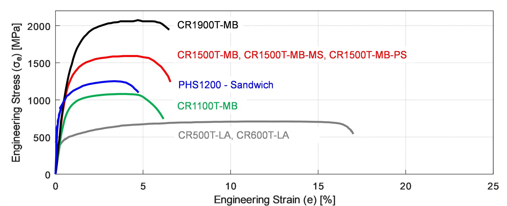
Figure 2: Stress-strain curves of commercially available PHS and PQS grades after quenching. (re-created after: B-18,Y-12, R-14).
The UniSteel Concept: One Alloy, Many Properties
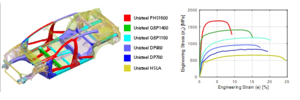
In late 2021, researchers from China came up with a concept of using one chemistry (a modified 22MnB5) combined with different thermal processes to tailor the production of differing mechanical properties. Thus, it became possible to make a whole car from the same alloy, named as “UniSteel”. The different properties and their use areas are shown in Figure 3. The research was published in Science magazine.L-68
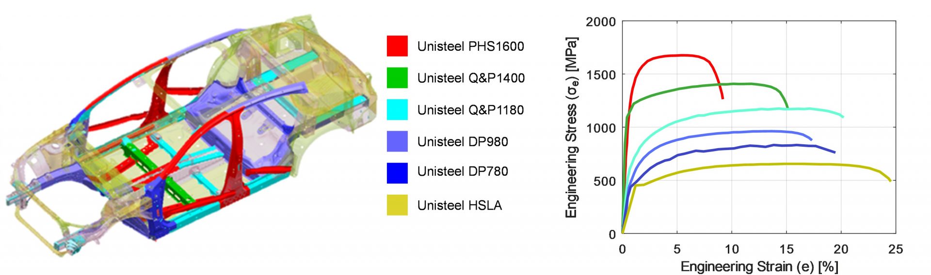
Figure 3: UniSteel concept: (a) material usage in a car body, (2) mechanical properties after heat treatments (re-created after R-14)
The Future: BQP and SIBORA Development
In 2025, a German consortium developed a new grade 37SiB6 and a new process route called Bainitizing, Quenching and Partitioning (BQP). Similar to the Chinese UniSteel concept, the new SIBORA (Silicon Boron with Retained Austenite) material can have various strength and elongation levels. Both the process and resulting mechanical properties are given in Figure 4. Different strength levels can be achieved by changing the bainitizing temperature between 360 and 460°C (680 and 860°F).O-15
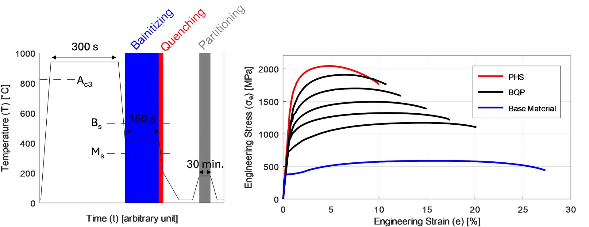
Figure 4: (a) the BQP process (shown here is 360°C bainitizing temperature), (b) the mechanical properties after PHS or BQP processes (re-created after O-15).
We encourage you to visit this steel grades page to learn more about these grades available for Press Hardening, and head to this PHS and PQS Overview page for our PHS Primer. Thank you to Eren Billur for providing this information.
 Thanks go to Eren Billur, Ph.D. for his contribution of this article to the AHSS Insights blog. Eren Billur is the Technical Manager of Billur Makine and Billur Metal Form, based in Ankara, Turkey, specializing in advanced sheet metal forming technologies. He holds a Ph.D. in Mechanical Engineering from The Ohio State University and has extensive experience in material characterization, sheet metal forming processes, and finite element simulations. Eren has contributed significantly to the understanding and application of hot stamping and advanced high-strength steels (AHSS) in the automotive industry. He is a regular columnist for MetalForming Magazine’s “Cutting Edge” column and has authored numerous scientific papers and book chapters, including contributions to the WorldAutoSteel AHSS Applications Guidelines. Passionate about advancing manufacturing knowledge, Eren provides engineering consulting, training, and simulation services worldwide, helping manufacturers optimize forming processes and successfully implement new-generation AHSS materials.