Blog, homepage-featured-top, main-blog
Grade Options and Corrosion Protection Considerations When Deciding How A Part Gets Formed
Automakers contemplating whether a part is cold stamped or hot formed must consider numerous ramifications impacting multiple departments. Our prior blog on this topic highlighted the equipment differences and the property development differences between each approach. We continue this blog series, now focusing on grade options and corrosion protection.
The discussions below relative to cold stamping are applicable to any forming operation occurring at room temperature such as roll forming, hydroforming, or conventional stamping. Similarly, hot stamping refers to any set of operations using Press Hardening Steels (or Press Quenched Steels), including those that are roll formed or fluid-formed.
Grade Options for Cold Stamped or Hot Formed Steel
There are two types of parts needed for vehicle safety cage applications: those with the highest strength that prevent intrusion, and those with some additional ductility that can help with energy absorption. Each of these types can be achieved via cold stamping or hot stamping.
When it comes to cold stamped parts, many grade options exist at 1000 MPa that also have decent ductility. The advent of the 3rd Generation Advanced High Strength Steels adds to the tally. Most of these top out at 1200 MPa, with some companies offering cold-formable Advanced High Strength Steels with 1400 or 1500 MPa tensile strength. The chemistry of AHSS grades is a function of the specific characteristics of each production mill, meaning that OEMs must exercise diligence when changing suppliers.

Figure 1: Stress-strain curve of industrially produced QP980.W-35
Martensitic grades from the steel mill have been in commercial production for many years, with minimum strength levels typically ranging from 900 MPa to 1470 MPa, depending on the grade. These products are typically destined for roll forming, except for possibly those at the lower strengths, due to limited ductility. Until recently, MS1470, a martensitic steel with 1470 MPa minimum tensile strength, was the highest strength cold formable option available. New offerings from global steelmakers now include MS1700, with a 1700 MPa minimum tensile strength, as well as MS 1470 with sufficient ductility to allow for cold stamping. Automakers have deployed these grades in cold stamped applications such as crossmembers and roof reinforcements.

Figure 2: Cold-Stamped Martensitic Steel with 1500 MPa Tensile Strength used in the Nissan B-Segment Hatchback.K-57
Until these recent developments, hot stamping was the primary option to reach the highest strength levels in part shapes having even mild complexity. Under proper conditions, a chemistry of 22MnB5 could routinely reach a nominal or aim strength of 1500 MPa, which led to this grade being described as PHS1500, CR1500T-MB, or with similar nomenclature. Note that in this terminology, 1500 MPa nominal strength typically corresponds to a minimum strength of 1300 MPa.
The 22MnB5 chemistry is globally available, but the coating approaches discussed below may be company-specific.
Newer PHS options with a modified chemistry and subsequent processing differences can reach nominal strength levels of 2000 MPa. Other options are available with additional ductility at strength levels of 1000 MPa or 1200 MPa. A special class called Press Quenched Steels have even higher ductility with strength as low as 450 MPa.
The spectrum of grades available for cold-stamped and hot formed steel parts allows automakers to fine-tune the crash energy management features within a body structure, contributing to steel’s “infinite tune-ability” capability which gives automotive engineers design flexibility and freedoms not available from other structural materials.
Corrosion Protection
Uncoated versions of a grade must take a different chemistry approach than the hot dip galvanized (GI) or hot dipped galvannealed (HDGA) versions since the hot dip galvanizing process acts as a heat treatment cycle that changes the properties of the base steel. Steelmakers adjust the base steel chemistry to account for this heat treatment to ensure the resultant properties fall within the grade requirements.

Figure 3: Schematic of a typical hot-dipped galvanizing line with galvanneal capability.
This strategy has limitations as it relates to grades with increasing amounts of martensite in the microstructure. Complex thermal cycles are needed to produce the highly engineered microstructures seen in advanced steels. Above a certain strength level, it is not possible to create a GI or HDGA version of that grade.
For example, when discussing fully martensitic grades from the steel mill, hot dip galvanizing is not an option. If a martensitic grade needs corrosion protection, then electrogalvanizing is the common approach since an EG coating is applied at ambient temperature, which is low enough to avoid negatively impacting the properties. Automakers might choose to forgo a galvanized coating if the intended application is in a dry area that is not exposed to road salt.

Figure 4: Schematic of an electrogalvanizing line.
For press hardening steels, coatings serve multiple purposes. Without a coating, uncoated steels will oxidize in the austenitizing furnace and develop scale on the surface. During hot stamping, this scale layer limits efficient thermal transfer and may prevent the critical cooling rate from being reached. Furthermore, scale may flake off in the tooling, leading to tool surface damage. Finally, scale remaining after hot stamping is typically removed by shot blasting, an off-line operation that may induce additional issues.
Using a hot dip galvanized steel in a conventional direct press hardening process (blank -> heat -> form/quench) may contribute to liquid metal embrittlement (LME). Getting around this requires either changing the steel chemistry from the conventional 22MnB5 or using an indirect press hardening process that sees the bulk of the part shape formed at ambient temperatures followed by heating and quenching.
Those companies wishing to use the direct press hardening process can use a base steel having an aluminum-silicon (Al-Si) coating, providing that the heating cycle in the austenitizing furnace is such that there is sufficient time for alloying between the coating and the base steel. Welding practices using these coated steels need to account for the aluminum in the coating, but robust practices have been developed and are in widespread use.
For more information about PHS grades and processing, see our Press Hardened Steel Primer.

Danny Schaeffler is the Metallurgy and Forming Technical Editor of the AHSS Applications Guidelines available from WorldAutoSteel. He is founder and President of Engineering Quality Solutions (EQS). Danny wrote the monthly “Science of Forming” and “Metal Matters” column for Metalforming Magazine, and provides seminars on sheet metal formability for Auto/Steel Partnership and the Precision Metalforming Association. He has written for Stamping Journal and The Fabricator, and has lectured at FabTech. Danny is passionate about training new and experienced employees at manufacturing companies about how sheet metal properties impact their forming success.
Blog, homepage-featured-top, main-blog
The WorldAutoSteel Steel E-Motive program has been moving along now for nearly a year, and we’d like to share an update with you, our engineering colleagues, on some of the design decisions we’re facing. If you recall, the Steel E-Motive program is designing vehicle concepts for Mobility as a Service (MaaS), characterized by autonomous, electric, ride sharing vehicles.
Some Background
We partnered with Ricardo headquartered in the UK to conduct the design and engineering of the vehicles. Ricardo was selected for their well-known reputation for innovation, their demonstrated knowledge of vehicle powertrains and electrification and their commitment to sustainable transportation. Our steel members subject matter experts work with Ricardo via various teams and working groups to push the envelope of steel applications. And given our pandemic, all of this currently occurs via virtual meetings.
Targeting technologies available for deployment in 2030+, we are considering the impacts to vehicle manufacturers, fleet operators and the ride hailing customer, as MaaS inevitably leads to an increase in demand for vehicle sharing, rental models and ride-hailing services over the next decade. We can represent these requirements as shown in Figure 1. On the left you’ll see broad needs for the critical stakeholders including space efficiency, flexibility and total cost of ownership. Those requirements translate into 12 key considerations for the mobility service provider, shown on the right, aimed at delivering value to customers and a sustainable and profitable business model. These considerations then require innovative design, engineering and materials applications.
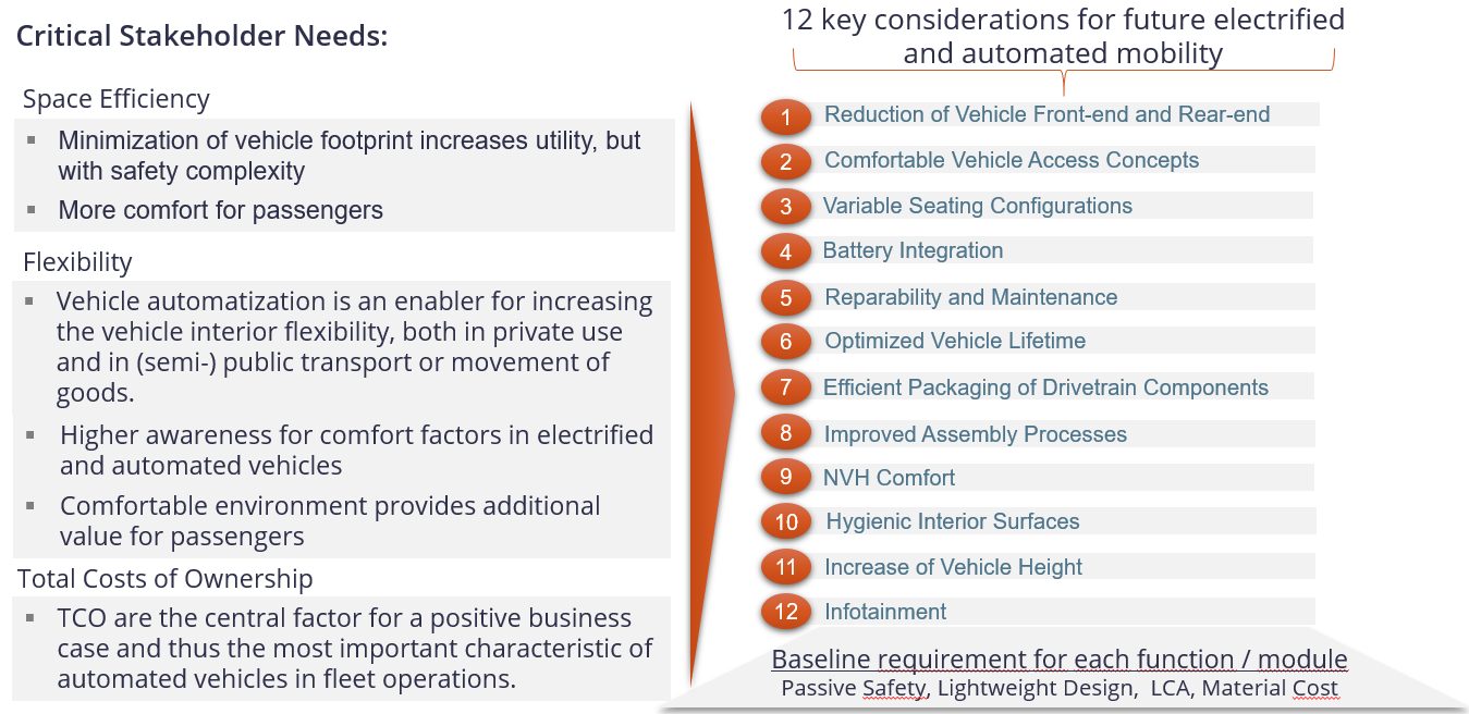
Figure 1: MaaS key attributes and functions.
There are four main phases to Steel E-Motive (Figure 2). Phase 0 was a 3-month pre-study, beginning 30 June 2020, to review and confirm vehicle targets, essentially defining the foundations, goals and approach for the project. On 1 October 2020, we entered the Phase 1 concept engineering, exploring the challenges and steel solutions for Level 5 autonomous vehicles. Essentially, we are designing the body structure in this Phase, utilizing CAE tools to guide us. Phase 2 focusses on further refinement and optimization of the selected body concept, and ensuring the design is fully validated as there will be no working prototypes or hardware produced in the project. Phase 3 will be the roll out and dissemination activities, although you will see from the Steel E-Motive website and blogs that we are continually releasing material throughout the project.
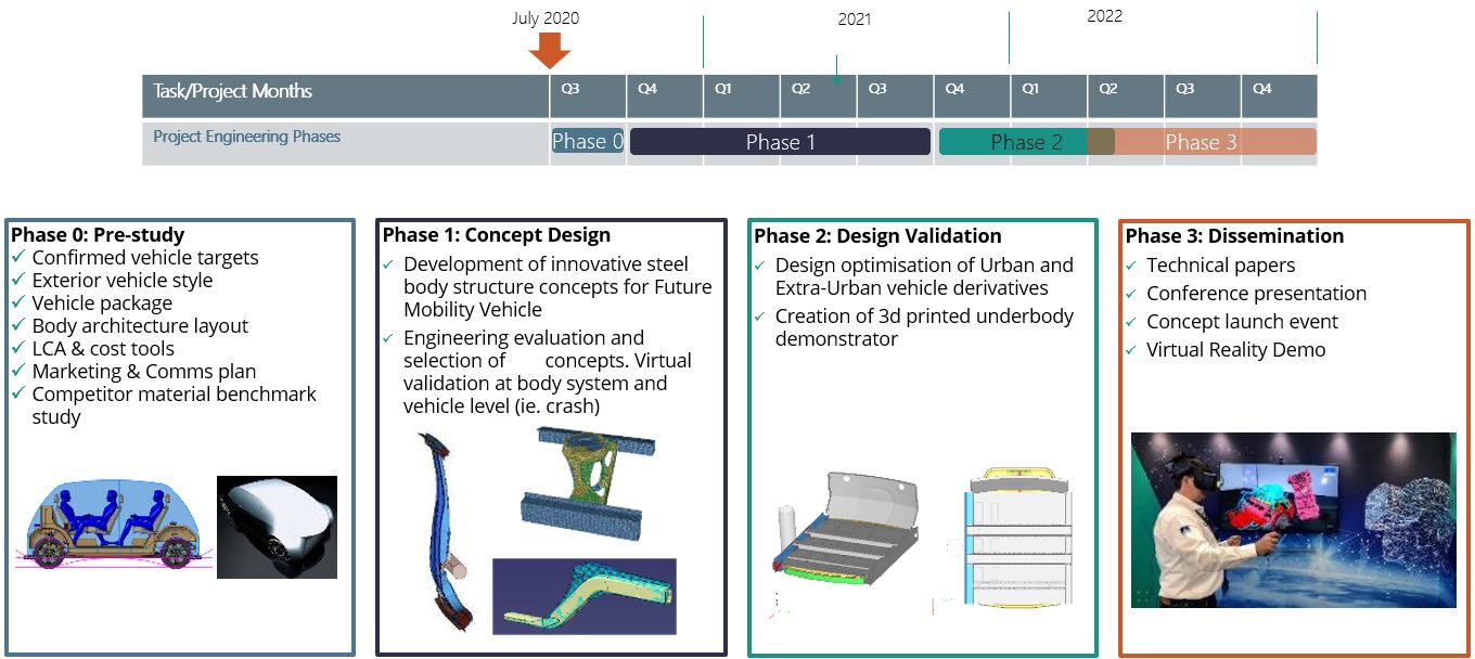
Figure 2: Project timing and key activities.
We’ll be disclosing detailed targets and specifications later in the program, but Figure 3 provides overall dimensions. Battery electric will be the primary propulsion with competitive range. There are two variants: urban for inner city and shorter journeys, and an extra-urban variant for longer city-to-city (or city-to-airport) journeys. With Level 5 autonomy, there are no direct driver interfaces such as the steering column and pedals. You can see from the Figure that the vehicles are fairly compact. The urban variant sits between a European B and C segment in size. The extra-urban vehicle has a stretched wheelbase and can accommodate up to six passengers and a greater luggage capacity.
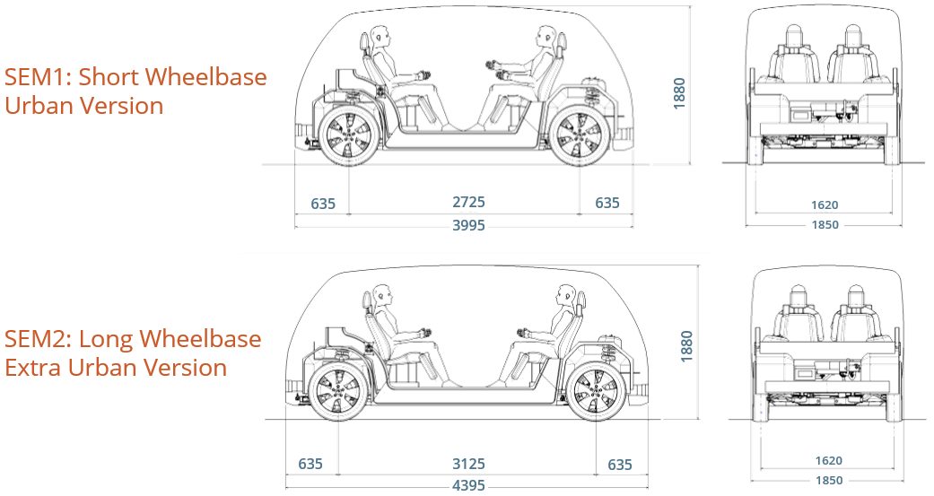
Figure 3: SEM vehicle technical specification and dimensions – base vehicle geometry.
The vehicles will be engineered and purposed for global application; therefore, we are considering the major global crash and safety standards and load cases. High volume production is targeted, greater than 250,000 units per annum, and a hypothetical production date of 2030, which influences the steel grades and fabrication processes considered. Third Generation AHSS (3rd Gen AHSS) and press-hardened steels continue to evolve with higher strength and improved formability. Between these innovative product capabilities, we are addressing the challenges associated with Mobility as a Service and tackling geometries that otherwise would have been difficult to produce.
To further assist in the design and manufacture of efficient vehicle structures, there are many new manufacturing processes, such as roll forming and hot stamping, that help fabricate these stronger materials effectively, while often doubling material use efficiency. Figure 4 provides a list of technologies that will be considered for Steel E-Motive.
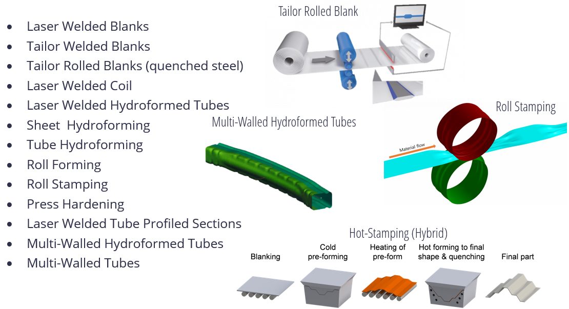
Figure 4: Steel technologies included in SEM’s portfolio.
With the portfolio of steel product and manufacturing processes already available and the addition of those forecasted for future commercial availability, we are expecting innovations that will be a roadmap for future mobility vehicle manufacturers.
Our end goal is to demonstrate multi-purpose opportunities for the vehicles via a modular architecture enabled by the application of innovative steel solutions. These solutions will help Steel E-Motive achieve a low environment footprint measured over the vehicle Life Cycle, and meet global crash standards while delivering the lowest Total Cost of Ownership (TCO).
To reach our goal of demonstrating steel innovation in this program, we are using a theoretical frameworkH-2 as a guide, shown in Figure 5, considering innovation at an architectural level. That is, using body structure load paths shown in the vertical axis, and modular innovation for the major body components such as battery enclosure, side/crash rails, shown in the horizontal axis. Combining innovation levels and types of the two axes should enable us to demonstrate radical innovation in Steel E-Motive.
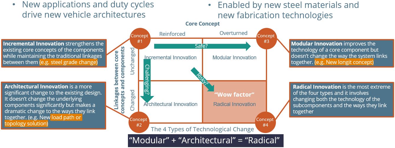
Figure 5: Steel E-Motive explores and demonstrates steel innovation. Exploring “modular” and “architectural” innovations for 2030 production.
Design Challenges
Figure 6 reveals an early or basic Steel E-Motive architecture. You can see that Level 5 autonomy creates both design freedoms that allow new occupant seating positions, while also creating challenges for short front and rear overhangs. We have an open pod-type structure with large door apertures for enhanced occupant ergonomics.
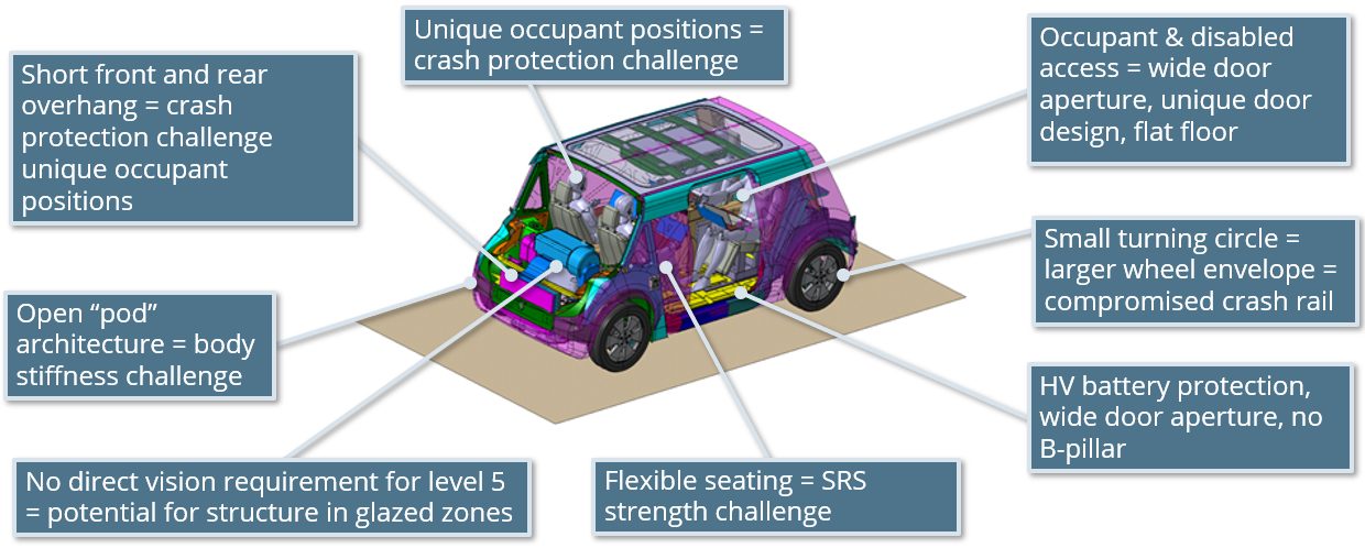
Figure 6: Challenges and opportunities of Level 5 autonomous MaaS battery electric vehicle.
Passenger comfort is key for MaaS vehicles. The open pod structure may give challenges with the air cavity mode coupling with structural modes. With occupants in different positions, we have different NVH source-path-receiver paths to consider. The larger door aperture gives us an inherent deficiency in overall body structure stiffness, for which we need to compensate. As with any BEV, the mass of the battery suspended on the lower structure may reduce body modes to frequencies that interact with other vehicle systems such as suspension modes. With a lot of emphasis on lower structure crash zones and battery protection, we may encounter some lower frequency upper body modes (such as lozenging), especially as we are targeting low overall body mass. These NVH risks and challenges are being addressed by taking a modal mapping approach, utilizing steel’s inherent high structural stiffness properties and undertaking thorough NVH simulation throughout the engineering phases.
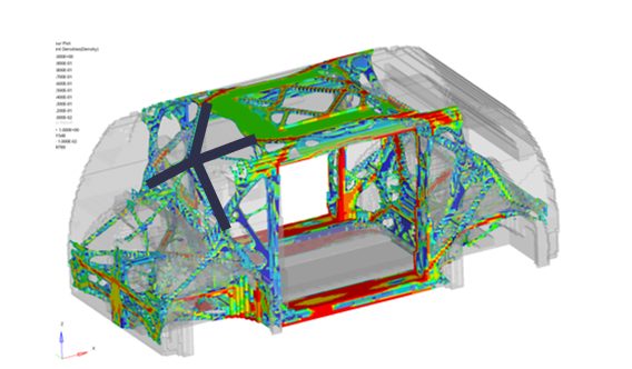
Level 5 autonomy removes the requirements for driver vision and obscuration, but we do need to acknowledge passenger comfort issues, such as motion sickness. Consequently the designs consider a good level of outward visibility. However, we now have the freedom to place structure where we could not previously. We are using 3D topology FEA tools to help determine the optimum placement of structure in the body, and we have allowed the tool the freedom to place structure in the front and rear glazed areas. In the Figure 7 example, the software is recommending some structural members across the front windscreen, and further analysis shows that this has the potential to give us an overall Body-In-White weight saving as the load paths are more evenly distributed.
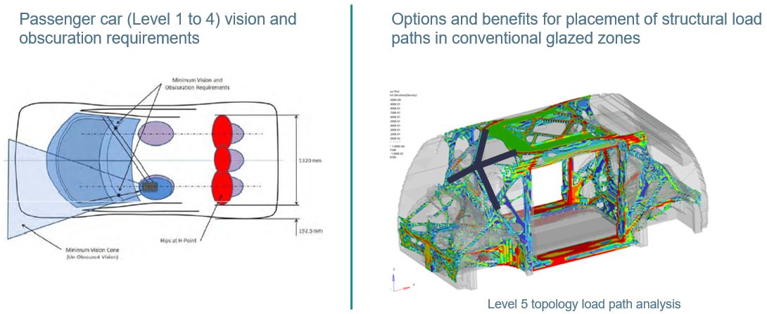
Figure 7: Level 5 autonomy removes the driver vision and obscuration requirements—an opportunity for new solutions.
To summarize the Steel E-Motive engineering activities, we are currently exploring the numerous challenges and opportunities that Level 5 autonomous BEVs provide us. We are in the concept phase, investigating both the overall body structure layout and load paths, as well as developing components and modules utilizing the unique properties of steel.
We expect to complete the program with full virtual concepts by December 2022. Our plans are to unveil more and more of the design concepts over the months to come, and we’ll be using virtual reality and other tools to communicate the concepts’ engineering. We invite you to subscribe at the website to receive all the news that will be coming out of the program, including more technical details as they become available. You can do that at www.steelemotive.world. We’re excited to share Steel E-Motive innovations in the future!
Joining, Laser Welding, Press Hardened Steels
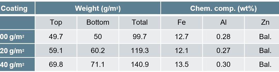
This studyR-25, conducted by the Centre for Advanced Materials Joining, Department of Mechanical & Mechatronics Engineering, University of Waterloo, and ArcelorMittal Global Research, utilized 2mm thick 22MnB5 steel with three different coating thicknesses, given in Table 1. The fiber laser welder used 0.3mm core diameter, 0.6mm spot size, and 200mm beam focal length. The trials were done with a 25° head angle with no shielding gas but high pressure air was applied to protect optics. Welding passes were performed using 3-6kW power increasing by 1 kW and 8-22m/min welding speed increasing by 4m/min. Compared to the base metal composition of mostly ferrite with colonies of pearlite, laser welding created complete martensitic composition in the FZ and fully austenized HAZ while the ICHAZ contained martensite in the intergranular regions where austenization occurred.
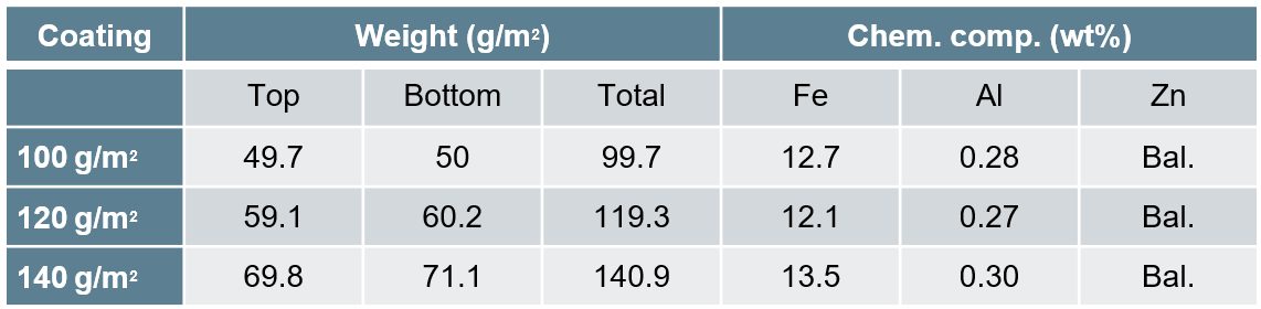
Table 1: Galvanneal Coatings.R-25
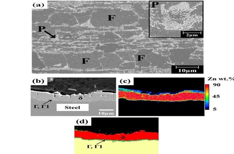
Figure 1: Base metal microstructure(P=pearlite, F=ferrite, Γ=Fe3Zn10, Γ1=Fe5Zn21 and δ=FeZn10).R-25
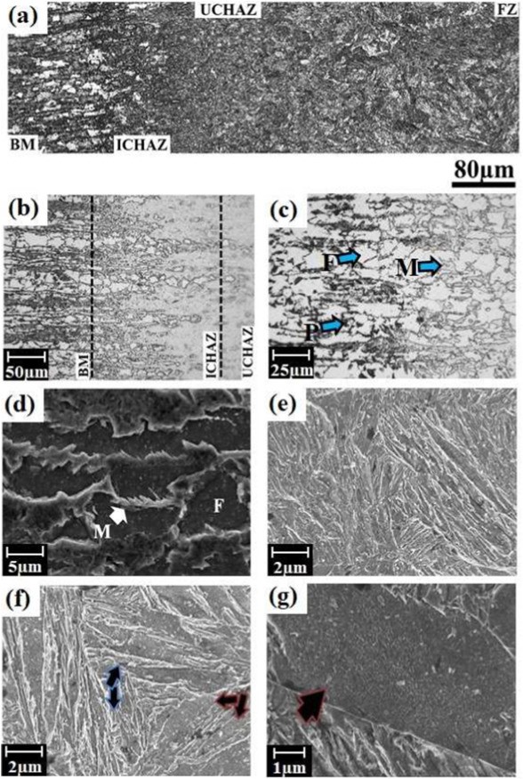
Figure 2: Welded microstructure — (a) overall view, (b) HAZ, (c) ICHAZ at low and (d) high magnifications, (e) UCHAZ (f) FZ, and (g) coarse-lath martensitic structure (where M; martensite, P: pearlite, F: ferrite).R-25
Given the lower boiling temperature of Zn at 900 °C as compared to Fe, the interaction of the laser with the Zn plasma that forms upon welding affects energy deliverance and depth of penetration. Lower coating weight of (100 g/m2) resulted in a larger process window as compared to (140 g/m2). Increased coating weight will reduce process window and need higher power and lower speeds in order to achieved proper penetration as shown in Figure 3 and Figure 4. Depth of penetration due to varying welding parameters was developed:
d=(H-8.6+0.08C)/(0.09C-4.8)
[d= depth of penetration(mm), H= heat input per unit thickness(J/mm2), C= coating weight(g/m2)]
Given the reduction in power deliverance, with an increase in coating weight there will be an expected drop in FZ and HAZ width. Regardless of the coating thickness, the HAZ maintained its hardness between BM and FZ. No direct correlation between coating thickness and YS, UTS, and elongation to fracture levels were observed. This is mainly due to the failure location being in the BM.
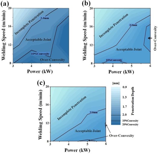
Figure 3: Process map of the welding window at coating weight of (a) 100 g/m2, (b) 120 g/m2, and (c) 140 g/m2.R-25
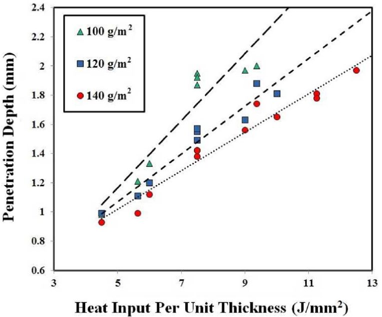
Figure 4: Heat input per unit thickness vs depth of penetration.R-25
Blog, main-blog
The Beginnings of PHS Use
Press hardening, as we know it today, was developed in Luleå, Sweden, by Norrbottens Järnverks AB (abbreviated as NJA, translated as Norrbotten Iron Works). The first patent application was completed in 1973 and awarded in 1977.N-23 The technology was first commercialized in agriculture components, where the high strength of Press Hardened Steels (PHS) was favored for wear resistance.B-45
In 1984, automotive applications of PHS started with the Saab 9000 side impact door beams, as seen in Figure 1. A total of 4 parts were used in this car.A-66 The uncoated blanks were almost half the thickness of a cold stamped beam.T-26
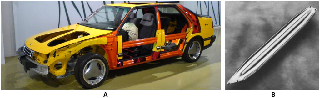
Figure 1: Door beams of the Saab 9000 (1984-1998): (a) A see-through car in Saab MuseumS-82, (b) the hot stamped part.L-42
The majority of the PHS parts were door beams through the mid-1990s, with approximately 6 million beams produced in 1996. By this time, the demand for bumper beams was also increasing.F-31 By the end of 1996, the European New Car Assessment Program (EuroNCAP) was formed, which increased the pressure on the OEMs for improved crashworthiness.T-26 In 1998, both the new Volvo S80L-44 and Ford Focus5 were equipped with Press Hardened bumper beams.
The year 1998 saw the development of one of the most important breakthroughs in Press Hardening technology. French steel maker Usinor developed an aluminum-silicon (AlSi) pre-coated steel, commercialized as Usibor 1500 (indicating the typical tensile strength, 1500 MPa.C-24, L-39 In 2000, BMW rolled out its new 3 series convertible. In this vehicle, the A-pillar is made from 3 mm thick uncoated, PHS sheet. This was BMW’s first PHS application, and one of the first PHS A-pillar reinforcement.S-83, S-84 Accra started delivering roll formed PHS components for the Volvo V70, initially an optional 3rd row seating support. Approximately 10,000 parts/year were supplied.G-28
AlSi coated steel was first hot stamped at a French Tier 1 supplier, Sofedit.V-15 This grade was first used in the front bumper beam of the 2nd Generation Renault Laguna (2000-2007). Laguna 2 was the first car to receive a 5-star safety rating from Euro NCAP.V-10 AlSi coated blanks were also used in PSA Group’s Citroën C5 (1st Gen: 2001-2007) in the front bumper beam, and the A-pillars. These three parts weighed a total of 4.5 kg, approximately 1% of the total BIW weight, Figure 2a. About one month later, PSA Group started production of the compact hatchback Peugeot 307, which had five hot stamped components (A- and B-pillars and rear bumper beam). Unlike the Citroën C5, these parts were uncoated. The total weight was 12 kg, corresponding to 3.4% of the BIW weight.R-17, P-27
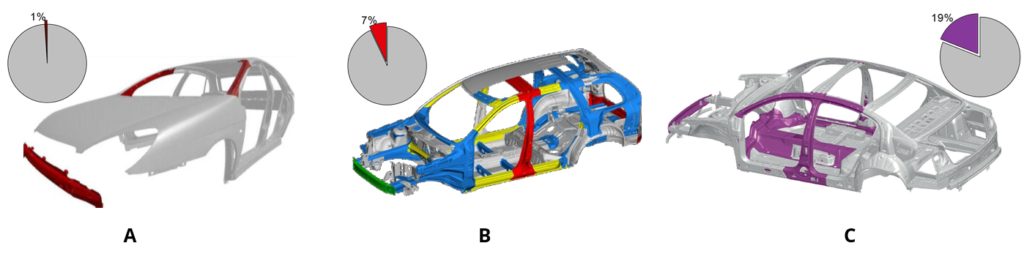
Figure 2: Increase in press hardened component usage: (a) 2001 Citroën C5P-27, (b) 2002 Volvo XC90L-29 and (c) 2005 VW Passat.H-50
Volvo started producing the XC90 SUV in 2002. The body-in-white with doors and closures weighed 531 kg.B-44 A total of 10 parts, weighing 37 kg are either roll formed or direct stamped PHS. This accounts for approximately 7% of the BIW weight.L-43 During its time, this was the highest use of PHS in car bodies. In Figure 2b, the Press Hardened components other than the 2nd row seat frame, which is a load bearing body part, are shown.
Accelerated Use and Globalization
The use of press hardened parts increased rapidly after the introduction of the VW Passat in 2005. This car had approximately 19% of its BIW (by weight) made from press hardened steels, Figure 2c. Some parts in this car saw the first use of varnish coated blanks in a two-step hybrid process. Three parts were produced using either an indirect or hybrid process, including the transmission tunnel.H-50
Following are a few highlights of PHS use in vehicle applications during this time period :
- In 2006, the Dodge CaliberK-37 and BMW X5P-28 were among the first cars to have tailor-rolled and Press Hardened components in their bodies (Figure 3).
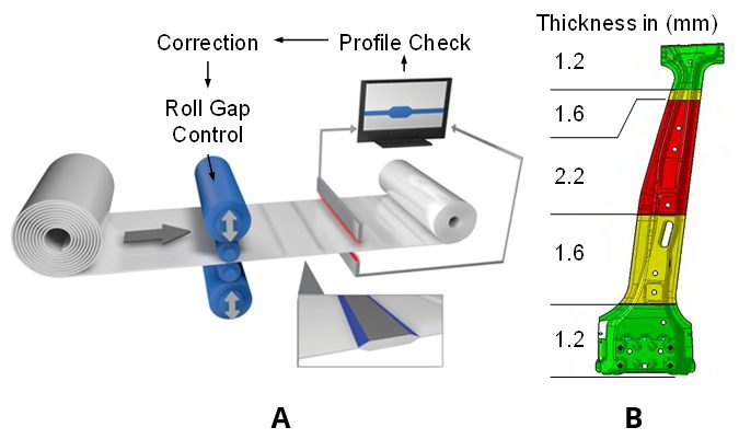
Figure 3: (a) Tailor Rolling ProcessZ-5, (b) B-pillar of BMW X5 (2nd Gen: 2006-2013).P-28
- BMW 7 Series (5th Gen: 2008-2015) became the first car to have Zn-coated Press Hardened components in its body-in-white. The car also contained uncoated parts, as shown in Figure 4 (next page). The total PHS usage in this car was approximately 16%.P-20
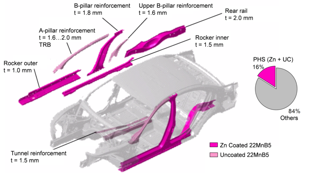
Figure 4: PHS usage in BMW 7 Series (5th Gen: 2008-2015) (re-created using P-20).
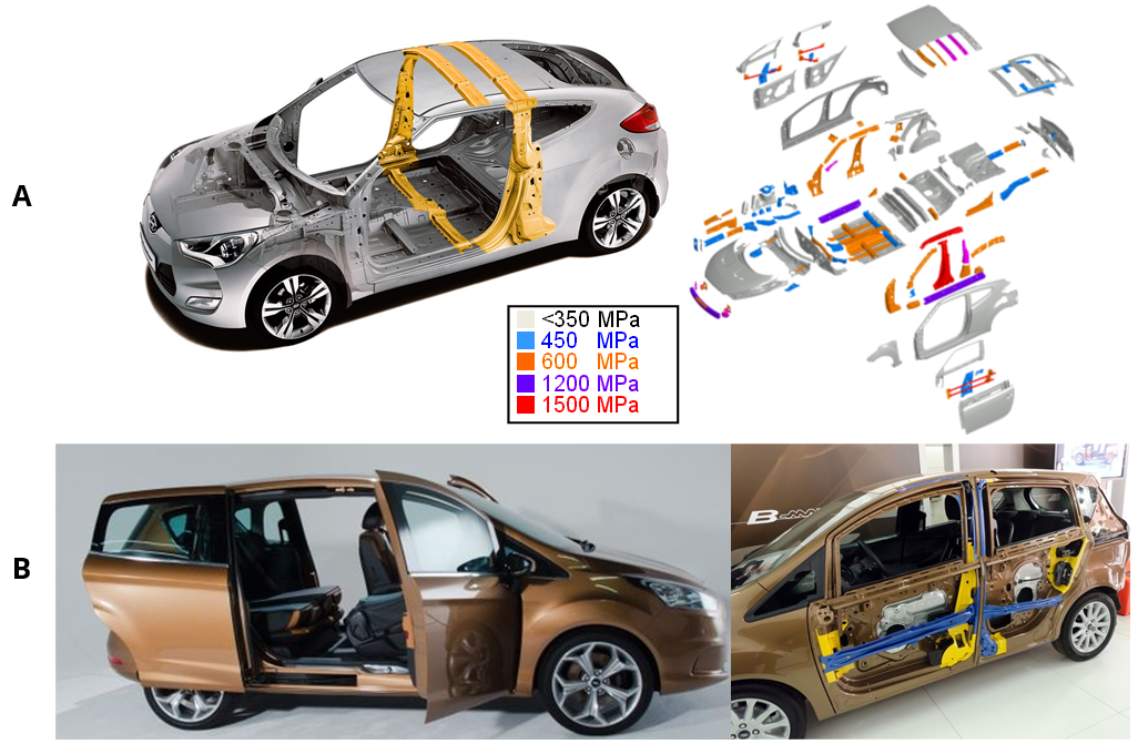
- Press hardening also allowed car makers to create unconventional cars. In 2011, Hyundai rolled out the 1st generation Veloster, a 3-door coupé (also known as 2+1, with one door on the driver side and 2 doors on the passenger side), and as such containing axisymmetric front doors. Thus, the car could not have a full B-ring, as illustrated in Figure 5a.B-14, R-19 Another unconventional design was the Ford B-Max subcompact MPV sold in Europe between 2012 and 2017. The car had conventional swing doors in the front and two sliding rear doors. A PHS B-pillar was integrated in the doors, providing ease of ingress. Its PHS components (integrated B-pillar in front and rear doors, door beams and cantrail) are shown with blue color in Figure 5b.B-14, L-45

Figure 5: Unconventional car designs with PHS: (a) Hyundai Veloster, asymmetric 2+1 doors coupé (re-created after Citation R-19), and (b) Ford B-Max, sub-compact MPV with integrated B-pillars in the doors.L-45
In 2013, the Acura MDX (3rd Gen: 2013-2020) became the first car to have a Hot Stamped door ring. The part was a tailor welded blank comprised of two sub-blanks, as shown in Figure 6a. The design saved about 6.2 kg weight per car and had high material utilization ratio thanks to sub-blank nesting optimization.A-67, M-46 One of the most recent PHS applications was in 2017 Chrysler Pacifica with 5 sub-blanks, as shown in Figure 6b. This car also has a PQS550 sub-blank at the lower B-pillar region.D-28
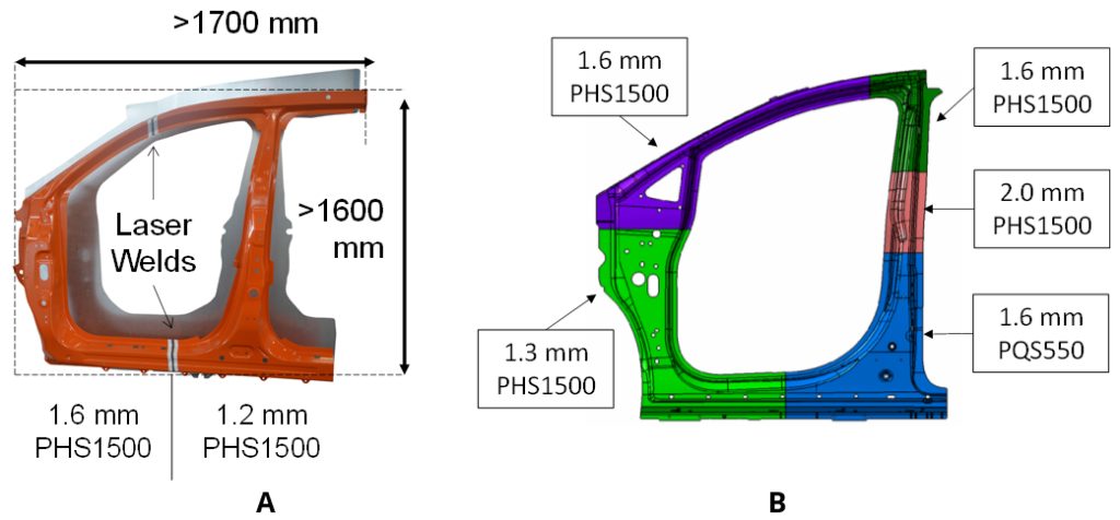
Figure 6: Hot stamped door rings: (a) First application in 2013 Acura MDX had 2 sub-blanks, (b) a more recent application in 2017 Chrysler Pacifica has five sub-blanks with PQS550 at the lower B-pillar (re-created after Citations B-14, A-67, D-28).
- Tubular hardened steels have been long used in car bodies, with minimal forming. Since 2013, a special 3-D hot bending and quenching (3DQ) process has been employed. One of the earliest uses of this technology was Mazda Premacy (known as Mazda 5 in some markets). The same process was also used in making the A-pillars of the Acura NSX (Honda NSX in some markets, 2016-present), as seen in Figure 7a.H-29 Since 2018, tubular parts formed with internal pressure, called form blow hardened parts, are used in the Ford Focus (4th Generation) (Figure 7b) and Jeep Wrangler (4th Generation).B-16, B-17
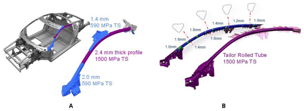
Figure 7: Tubular hardened steel usage in A-pillars of: (a) 2015 Acura NSXH-29, (b) 2018 Ford Focus.B-16
PHS Use in xEVs: Hybrid Electric, Battery Electric,
Plug-in Hybrid Electric & Fuel Cell Electric Vehicles
The first commercially available Hybrid Electric Vehicle (HEV) was the Toyota Prius (1st Gen: 1997-2003). The second-generation Prius (2003-2009) had very few Press Hardened components, as shown with red color in Figure 8a. This was the first time Toyota used hot stamped components.M-47 The third generation Prius (2009-2015) had approximately 3% of its BIW Press Hardened. In the 4th generation Prius released in 2015, the share of >980 MPa steels has risen to 19%.U-10 Figure 8b shows the Press Hardened parts in this latest Prius.K-38
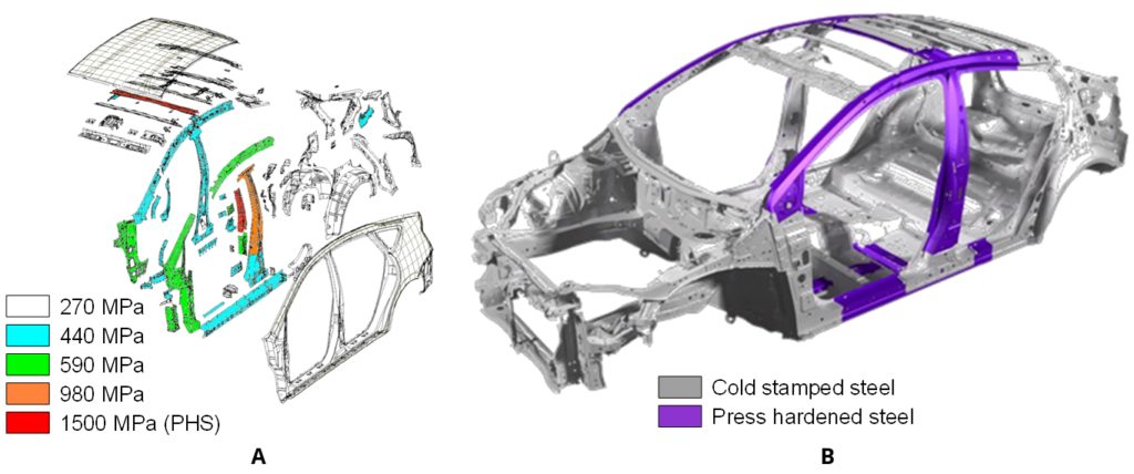
Figure 8: PHS usage in Toyota Prius: (a) 2nd generation (2003-2009) and (b) 4th generation (2015-present) (re-created after Citations M-47 and K-38)
The 2012 Tesla Model S and Model X launched using aluminium bodies, with PHS reinforcements in the pillars and the bumpers. Model S is known to have a roll-formed PHS bumper beam. High volume Model 3 and Model Y have a significant amount of press hardened components in their bodies.T-35
In 2011, General Motors started production of its first Plug-in Hybrid Electric Vehicle (PHEV), the Chevrolet Volt (known as Opel Ampera in EU and Vauxhall Ampera in the UK). This car had six Hot Stamped components, including A and B pillars, accounting for slightly over 5% of the BIW mass.P-29
The smaller BEV Chevrolet Bolt, launched in 2017, had aluminum closures, but a steel-intensive BIW that is 80% steel, 44% of which is Advanced High-Strength Steels including 11.8% PHS. Figure 9.A-69
Figure 9: Chevrolet Bolt Body Structure and Steel Content.A-69
In December 2020, Hyundai announced their new electric platform, E-GMP. The platform will utilize Press Hardened steel components to secure the batteries.H-52
Automakers have turned to PHS to manage the extra load of Fuel Cell powertrains as well. The first-generation Toyota Mirai had only Press Hardened B-pillars, cantrails and lateral floor members.T-38 The second generation has a number of parts with PHS in its under body as well.T-39
In 2018, Hyundai Nexo became the first fuel-cell car to be tested by EuroNCAP, achieving a 5-Star rating. The car has PHS A- and B-pillars, rocker reinforcements, and several under body components, as seen in Figure 10.H-53
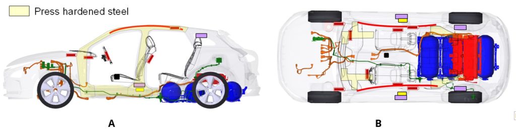
Figure 10: Press hardened steel usage in Hyundai Nexo Fuel Cell vehicle: (a) side view and (b) top view (re-created after Citation H-53).
Did you enjoy this story? You can find a much more detailed article here in the Guidelines with many more vehicle examples and history data.