This article summarizes a paper entitled, “An Evaluation of Friction Stir Spot Welding as a Method for Joining Ultra-thin Steel Sheet,” by Y. Hovansk, et al.H-10
The study analyzes Friction Stir Spot Welding (FSSW) as a process for assembly of two sheet stack ups. The steel sheet used for this study is CR4-GI, a hot dip galvanized ultra-low carbon interstitial free steel with a tensile strength of 280 MPa. Thicknesses of both 0.45 and 1.2 mm were used to create dissimilar thickness, two-sheet stack-ups. Preparation for joining via FSSW did not alter the zinc coating. FSSW joints were evaluated in lap shear tensile, T-peel, and cross tension.
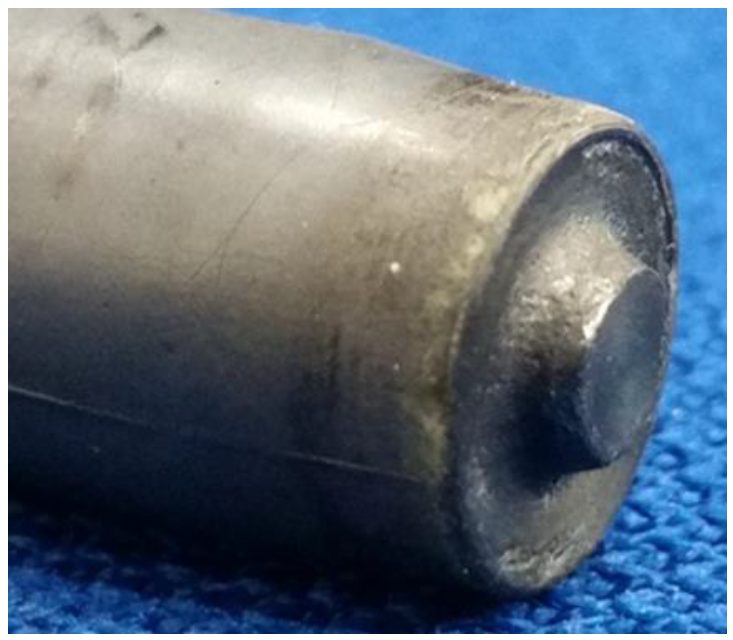
FSSW welds were welded with an EKasin injection molded, silicon nitride tool shown in Figure 1. All welds were performed at 1600 rpm.
Figure 1: Representative Picture of a Silicon-Nitride FSSW Tool with a 10-mm-diameter Shoulder and a 1.15-mm Probe Length.H-10
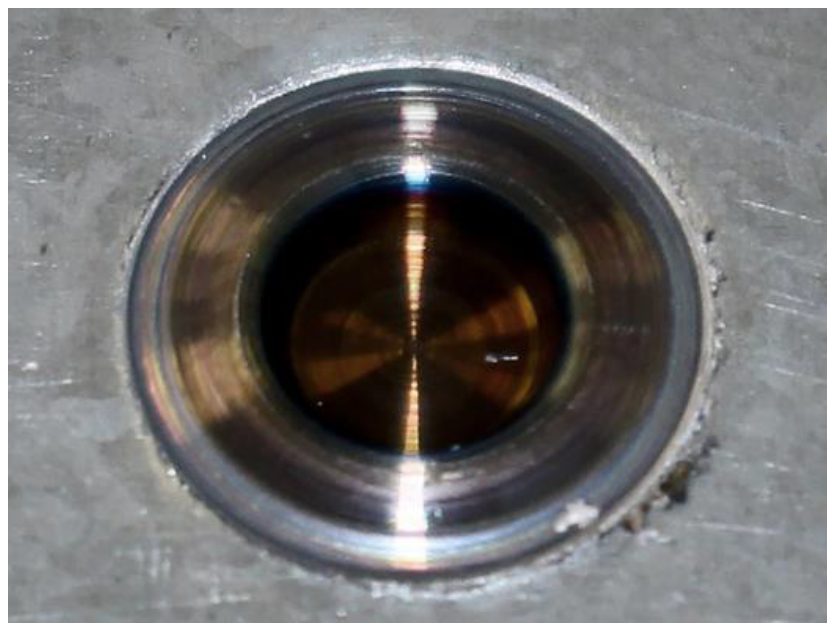
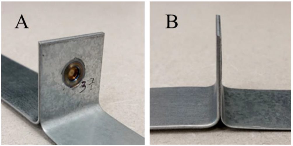
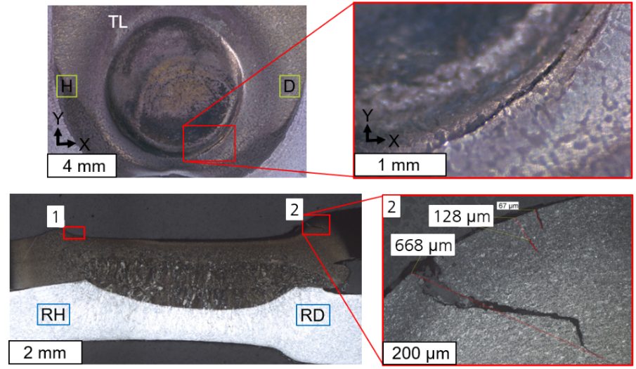
The zinc coating that originally covered the sheet surface was extruded beneath the FSSW tool to the outer edges of the weld as seen in Figure 2. Figure 3 shows a representative weld on a T-peel specimen.
Figure 2: Optical Image of the Top Surface of a Friction Stir Spot Weld in CR4-GI.H-10
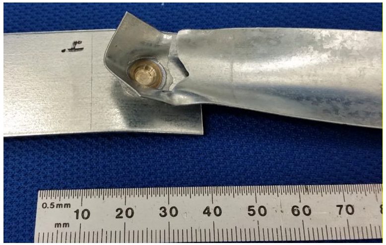
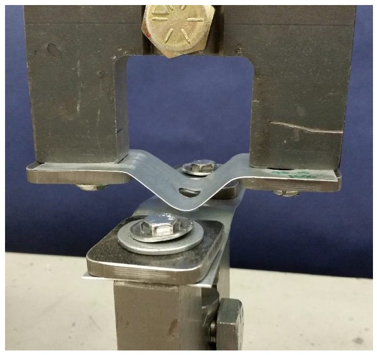
Figure 3: A T-Peel Specimen Produced on a 25-mm-wide Strips with FSSW 0.45- to 1.2-mm-thick CR4-GI.H-10
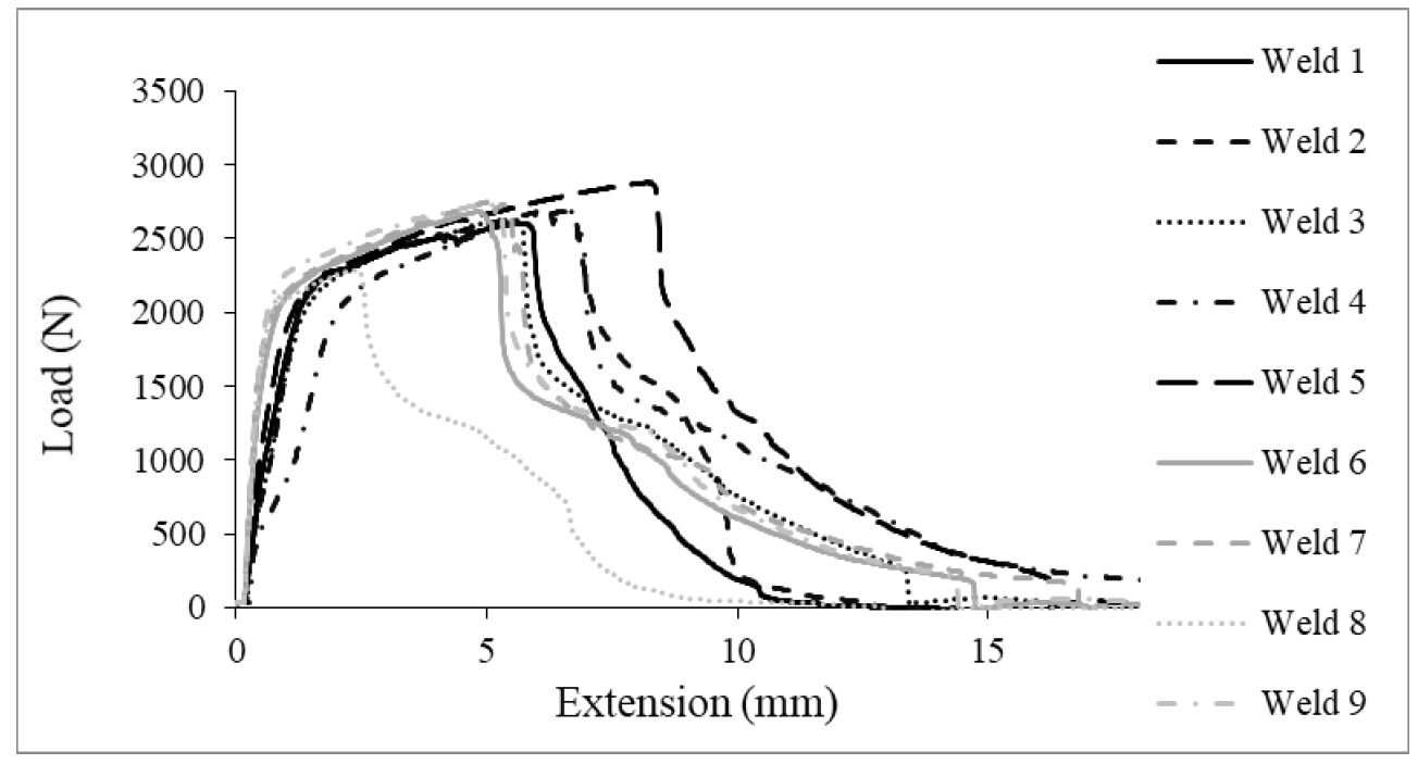
A minimum of 25 specimens were produced for each geometry tested, however, these specimens were performed at various times throughout weld development and data is shown below. Figure 4 shows the load-extension curves for a set of nine friction stir spot welds. Figure 5 shows a representative fracture of lap-shear tensile specimen.
Figure 4: Test Results for Lap-Shear Tensile Data of Friction Stir Spot Welds in 0.45-mm CR4-GI.H-10
Figure 5: Friction Stir Spot Weld in 0.45-mm CR4-GI Fractured in Lap-Shear Tensile.H-10
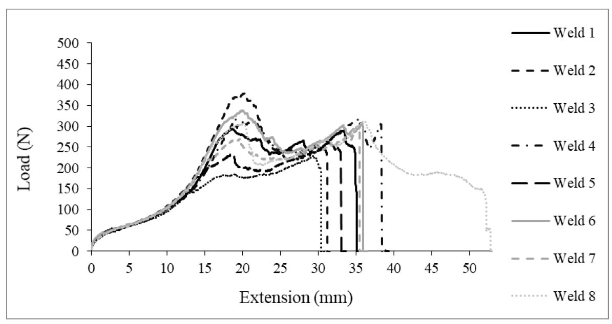
Figure 6 shows the load-extension curves for a set of eight friction stir spot welds tests in T-peel. A representative fracture of T-peel specimen is shown in Figure 7.
Figure 6: Test Results for T-Peel Data of Friction Stir Spot Welds in 0.45-mm CR4-GI.H-10
Figure 7: Friction Stir Spot Weld in 0.45-mm CR4-GI Fractured in T-Peel.H-10
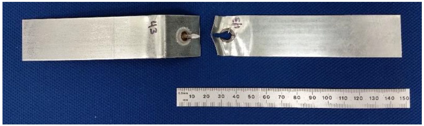
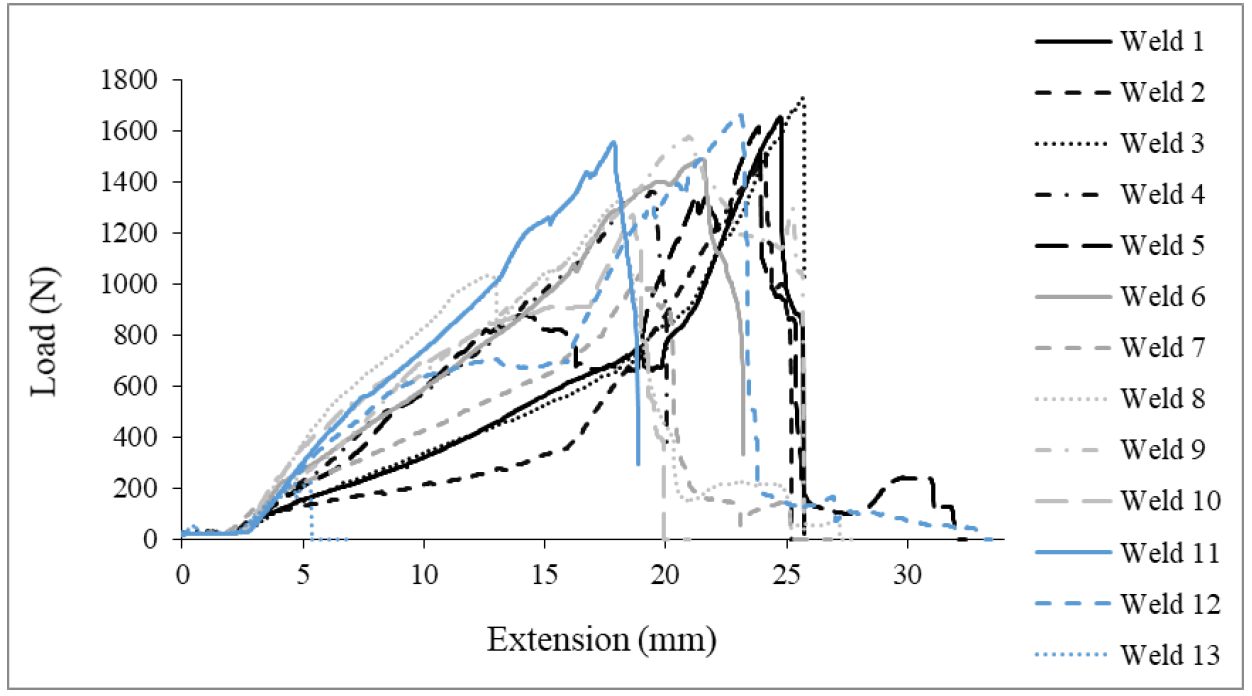
Figure 8 shows the load extension curves for a set of 13 friction stir spot welds tested in cross tension. Representative geometry and fracture of cross tension specimen are shown in Figure 9.
Figure 8: Test Results for Cross-Tension Data of Friction Stir Spot Welds in 0.45-mm CR4-GI.H-10
Figure 9: Friction Stir Spot Weld in 0.45-mm CR4-GI Fractured in Cross-Tension.H-10
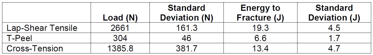
A table showing the overall results for the FSSW joints produced herein are shown in Table 1 below:
Table 1: Summary of Fracture Loads and Energies from Friction Stir Spot Welds made in Ultra-Thin CR4-GI for Three Unique Test Configurations.H-10
While each specific test orientation demonstrated the ability for the weld nugget to pull out of the ultra-thin top sheet and remain with the lower 1.2-mm-thick sheet, the overall ratios between fracture loads suggest there is an area for improvement with respect to T-peel.
A variety of steel grades are used to manufacture vehicle body structures and closures. Welding dissimilar Advanced High-Strength Steels (AHSS) in three and four layer stack-ups requires special considerations. In this section of the Guidelines are articles summarizing papers that have investigated welding dissimilar AHSS and stack ups and discovered important factors for consideration and implementation.
Liquid Metal Embrittlement (LME) during Resistance Spot Welding (RSW) can cause cracks when welding advanced high strength steels. Recent advances in steel metallurgy, resistance spot welding processing and accompanying simulation tools have substantially improved the way that LME can be handled in industrial practice. This article gives a brief overview of easy measures to implement when LME might potentially occur during production.
Introduction
During resistance spot welding of zinc-coated advanced high strength steels (AHSS) liquid metal embrittlement -related cracking may be observed. Since LME is often associated with a reduction of steel’s mechanical properties, it is desired to control its occurrence during production. An exemplary LME crack, forced with increased weld heat and deliberate electrode misalignment, is shown below.
Figure 1: A typical LME crack created under laboratory conditions by deliberately increasing the welding time and introducing 5° electrode tilt
Over the past several years, LME has been a a focus in welding research. It is now well-understood to the degree that it can be predicted and avoided with easy measures. Below is an overview of four key steps to address the potential of LME during automotive production.
Obtain the latest steel grades from your steel supplier
Over the past decade, steel producers have released AHSS with improved chemical compositions, helping to significantly reduce the occurrence of LME iIt is beneficial to talk with steel suppliers and ask about their latest AHSS grades, as these are likely far less sensitive to LME than previously tested grades. A recent study commissioned by WorldAutoSteel demonstrated that all five chosen material stack-ups from current production data did not show any LME even under exacerbated conditions. Only by choosing an especially difficult material stack-up could LME be forced to appear at all to conduct the study.
Read up on the current state of research for LME
WorldAutoSteel has published two studies on liquid metal embrittlement: One focused on lab conditions and the second on real-life stamped components. These studies provide an overview of all aspects of LME and how to manage and avoid LME issues.
Establish in-house testing protocols to gauge the sensitivity of your material stack-ups
To investigate LME in-house, it’s critical to establish a testing protocol that forces the cracks to appear and allows for comparison of different steels, stack-ups and welding parameters. as there There is currently no industry-wide agreed-upon testing standard.
Still, there is a good selection of well-documented procedures to choose from. The easiest procedure is to increase the welding time until cracks start to appear – keep in mind that you need to remove the zinc coating before you can observe any cracks on the surface.
Other methods are based on so-called “Gleeble testing” or on deliberately introducing imperfections like tilted electrodes or large gaps into the welds. As you establish a testing procedure in your lab, you can use it to evaluate LME occurrence in the stack-ups that you want to implement into body-in-whites.
Think about implementing LME mitigation strategies in your most difficult welds
Suitable measures should always be adapted to the specific use case. Generally, the most effective measures for LME prevention or mitigation are:
Avoidance of excessive heat input (e.g. excess welding time, current)
Avoidance of sharp edges on spot welding electrodes; instead use electrodes with larger working plane diameter, while not increasing nugget-size
Employing extended hold times to allow for sufficient heat dissipation and lower surface temperatures
Avoidance of improper welding equipment (e.g. misalignments of the welding gun, highly worn electrodes, insufficient electrode cooling)
These measures can be implemented in the planning stage and in an ongoing production environment to increase the LME-free process windows.
In Conclusion
While Liquid Metal Embrittlement may present a challenge when welding AHSS, it’s no longer an unpredictable threat. Thanks to advancements in steel development, welding techniques, and testing methods, manufacturers have the tools they need to reliably mitigate LME during production.
Staying informed, working closely with steel suppliers, implementing smart testing protocols, and applying targeted welding strategies can help automakers maintain both strength and quality in AHSS joints. With this proactive approach, LME doesn’t have to stand in the way of innovation in automotive manufacturing.
The discussions relative to cold stamping are applicable to any forming operation occurring at room temperature such as roll forming, hydroforming, or conventional stamping. Similarly, hot stamping refers to any set of operations using Press Hardening Steels (or Press Quenched Steels), including those that are roll formed or fluid formed.
Automakers contemplating whether a part is cold stamped or hot formed must consider numerous factors. This blog covers some important considerations related to welding these materials for automotive applications. Most important is the discussion on Resistance Spot Welding (RSW) as it is the dominating process in automotive manufacturing.
Setting Correct Welding Parameters for Resistance Spot Welding
Specific welding parameters need to be developed for each combination of material type and thickness. In general, the Hot Press (HP) steels require more demanding process conditions. One important factor is electrode force which should be higher for the HP steel than for cold press type steel of the same thickness. The actual recommended force will depend on the strength level, and the thickness of the steel. Of course, this will affect the welding machine/welding gun force capability requirement.
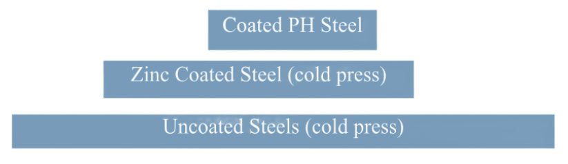
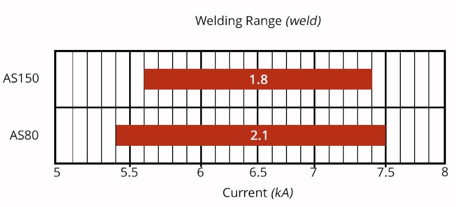
Another important variable is the welding current level and even more important is the current range at which acceptable welds can be made. The current range is weldability measurement, and the best indicator of the welding process robustness in the manufacturing environment and sometime called proceed window. Note the relative range of current for different steel types. A smaller process window may require more frequent weld quality evaluation such as for weld size.
Relative Current Range (process windows) for Different Steel Types
The Effect of Coating Type on Weldability
In all cases of resistance spot welding coated steels, it is imperative to move the coating away from the weld area during and in the beginning of the weld cycle to allow a steel-to-steel weld to occur. The combination of welding current, weld time and electrode force are responsible for this coating displacement.
For all the coated steels, the ability of the coating to flow is a function of the coating type and properties, such as electrical resistivity and melting point, as well as the coating thickness.
An example of cross sectioned spot welds made on Hot Press Steel with Aluminum -Silicon coating is shown below. It shows two coating thicknesses and the displaced coating at the periphery of weld. This figure also shows the difference in current range for the different coating thickness. The thicker coating shows a smaller current range. In addition, the Al-Si coating has a much higher melting point than the zinc coatings on the cold stamped steels, making it more difficult to displace from the weld area.
Hot Press Steel with Aluminum -Silicon
Liquid Metal Embrittlement and Resistance Spot Welding
Cold-formable, coated, Advance High Strength Steels such as the 3rd Generation Advanced HighStrength Steels are being widely used in automotive applications. One welding issue these materials encounter is the increased hardness in the weld area, that sometime results in brittle fracture of the weld.
Another issue is their sensitivity to Liquid Metal Embrittlement (LME) cracking. These two issues are discussed in detail on the WorldAutoSteel AHSS Guidelines website and our recently released Phase 2 Report on LME.
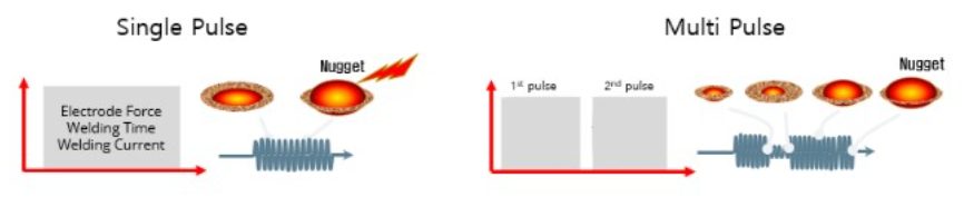
Resistance Spot Welding Using Current Pulsation
The most effective solution for the issues described above is using current pulsation during the welding cycle. A schematic description is shown below.
The pulsation allows much better control of the heat generation and the weld nugget development. The pulsation variables include the number of pulses (typically 2-4), the current level and time for each pulse, and the cool time between the pulses.
In summery, pulsation (and sometime current upslope) in Resistance Spot Welding proved to be beneficial for the following applications:
PHS steels
Coated Cold Stamped steels
Cold stamped Advance High Strength Steels
Multi materials stack-ups – As described in our articles here on 3T/4T and 5T Stack-Ups
Thanks is given to Menachem Kimchi, Associate Professor-Practice, Dept of Materials Science, Ohio State University and Technical Editor – Joining, AHSS Application Guidelines, for this article.