A-79
Citation:
A-79. Auto/Steel Partnership (2005). “Lightweight Front End Structure Phase 1 & 2 Final Report,” Available from https://a-sp.org/wp-content/uploads/2020/08/Lightweight-Front-End-Structures.pdf
Citation:
A-79. Auto/Steel Partnership (2005). “Lightweight Front End Structure Phase 1 & 2 Final Report,” Available from https://a-sp.org/wp-content/uploads/2020/08/Lightweight-Front-End-Structures.pdf
Citation:
J-26. J. Polewarczyk, “Overview: STEEL Lightweighting Projects,” 2008 Department of Energy Merit Review, Available from https://www.energy.gov/sites/prod/files/2014/03/f10/merit08_heimbuch_2.pdf
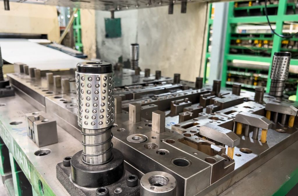
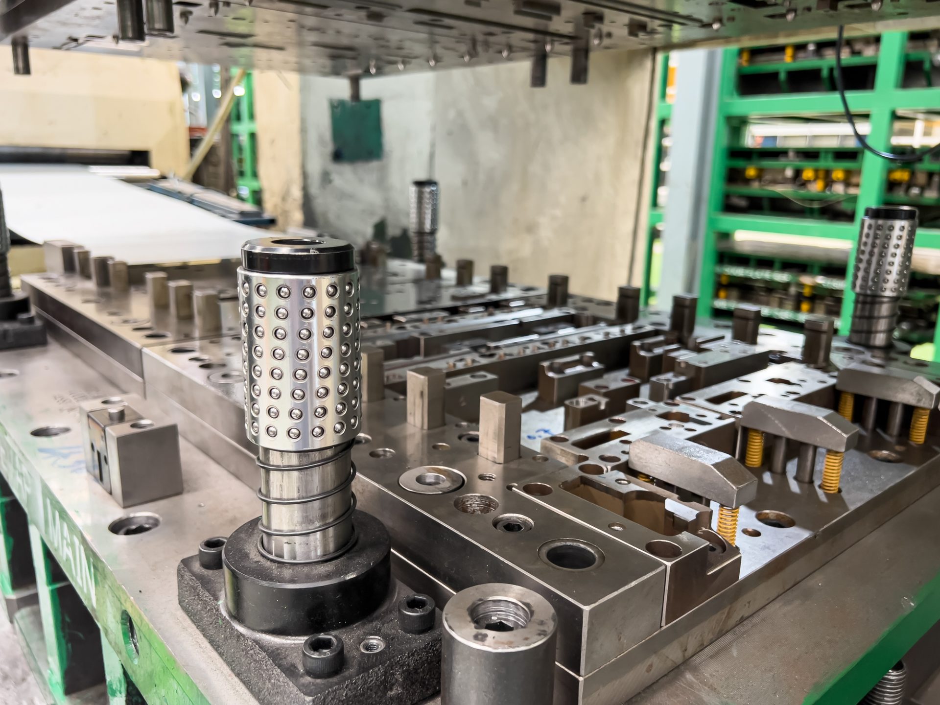
Automakers contemplating whether a part is cold stamped or hot formed must consider numerous ramifications impacting multiple departments. Over a series of blogs, we’ll cover some of the considerations that must enter the discussion.
The discussions relative to cold stamping are applicable to any forming operation occurring at room temperature such as roll forming, hydroforming, or conventional stamping. Similarly, hot stamping refers to any set of operations using Press Hardening Steels (or Press Quenched Steels), including those that are roll formed or fluid-formed.
There is a well-established infrastructure for cold stamping. New grades benefit from servo presses, especially for those grades where press force and press energy must be considered. Larger press beds may be necessary to accommodate larger parts. As long as these factors are considered, the existing infrastructure is likely sufficient.
Progressive-die presses have tonnage ratings commonly in the range of 630 to 1250 tons at relatively high stroke rates. Transfer presses, typically ranging from 800 to 2500 tons, operate at relatively lower stroke rates. Power requirements can vary between 75 kW (630 tons) to 350 kW (2500 tons). Recent transfer press installations of approximately 3000 tons capacity allow for processing of an expanded range of higher strength steels.
Hot stamping requires a high-tonnage servo-driven press (approximately 1000 ton force capacity) with a 3 meter by 2 meter bolster, fed by either a roller-hearth furnace more than 30 m long or a multi-chamber furnace. Press hardened steels need to be heated to 900 °C for full austenitization in order to achieve a uniform consistent phase, and this contributes to energy requirements often exceeding 2 MW.
Integrating multiple functions into fewer parts leads to part consolidation. Accommodating large laser-welded parts such as combined front and rear door rings expands the need for even wider furnaces, higher-tonnage presses, and larger bolster dimensions.
Blanking of coils used in the PHS process occurs before the hardening step, so forces are low. Post-hardening trimming usually requires laser cutting, or possibly mechanical cutting if some processing was done to soften the areas of interest.
That contrasts with the blanking and trimming of high strength cold-forming grades. Except for the highest strength cold forming grades, both blanking and trimming tonnage requirements are sufficiently low that conventional mechanical cutting is used on the vast majority of parts. Cut edge quality and uniformity greatly impact the edge stretchability that may lead to unexpected fracture.
Most cold stamped parts going into a given body-in-white are formed by a tier supplier. In contrast, some automakers create the vast majority of their hot stamped parts in-house, while others rely on their tier suppliers to provide hot stamped components. The number of qualified suppliers capable of producing hot stamped parts is markedly smaller than the number of cold stamping part suppliers.
Hot stamping is more complex than just adding heat to a cold stamping process. Suppliers of cold stamped parts are responsible for forming a dimensionally accurate part, assuming the steel supplier provides sheet metal with the required tensile properties achieved with a targeted microstructure.
Suppliers of hot stamped parts are also responsible for producing a dimensionally accurate part, but have additional responsibility for developing the microstructure and tensile properties of that part from a general steel chemistry typically described as 22MnB5.
Independent of which company creates the hot formed part, appropriate quality assurance practices must be in place. With cold stamped parts, steel is produced to meet the minimum requirements for that grade, so routine property testing of the formed part is usually not performed. This is in contrast to hot stamped parts, where the local quench rate has a direct effect on tensile properties after forming. If any portion of the part is not quenched faster than the critical cooling rate, the targeted mechanical properties will not be met and part performance can be compromised. Many companies have a standard practice of testing multiple areas on samples pulled every run. It’s critical that these tested areas are representative of the entire part. For example, on the top of a hat-section profile where there is good contact between the punch and cavity, heat extraction is likely uniform and consistent. However, on the vertical sidewalls, getting sufficient contact between the sheet metal and the tooling is more challenging. As a result, the reduced heat extraction may limit the strengthening effect due to an insufficient quench rate.
For more information, see our Press Hardened Steel Primer to learn more about PHS grades and processing!
Thanks are given to Eren Billur, Ph.D., Billur MetalForm for his contributions to the Equipment section, as well as many of the webpages relating to Press Hardening Steels at www.AHSSinsights.org.

Danny Schaeffler is the Metallurgy and Forming Technical Editor of the AHSS Applications Guidelines available from WorldAutoSteel. He is founder and President of Engineering Quality Solutions (EQS). Danny wrote the monthly “Science of Forming” and “Metal Matters” column for Metalforming Magazine, and provides seminars on sheet metal formability for Auto/Steel Partnership and the Precision Metalforming Association. He has written for Stamping Journal and The Fabricator, and has lectured at FabTech. Danny is passionate about training new and experienced employees at manufacturing companies about how sheet metal properties impact their forming success.
The transportation industry’s contribution to greenhouse gas (GHG) emissions and global warming is well documented and understood. Vehicle OEMs, fleet operators, and transport users all have responsibilities to reduce environmental impacts on the planet and contribute to meeting global emissions regulations.
Mobility as a Service (MaaS) solutions like WorldAutoSteel’s flaghip Steel E-Motive (SEM) program have the potential to contribute to a reduction in GHG emissions, helping to achieve these global targets and specific policy objectives. The Steel E-Motive engineering report, released in 2023, addresses the impact of emissions reduction using Life Cycle Assessment, with key results summarized in this article.
Life Cycle Assessment (LCA) is a methodology that evaluates the environmental impact of a product across its entire lifecycle. By understanding the impact across the entire vehicle life cycle, vehicle manufacturers evaluate trade-offs and assess the net impact of the product they’re using.
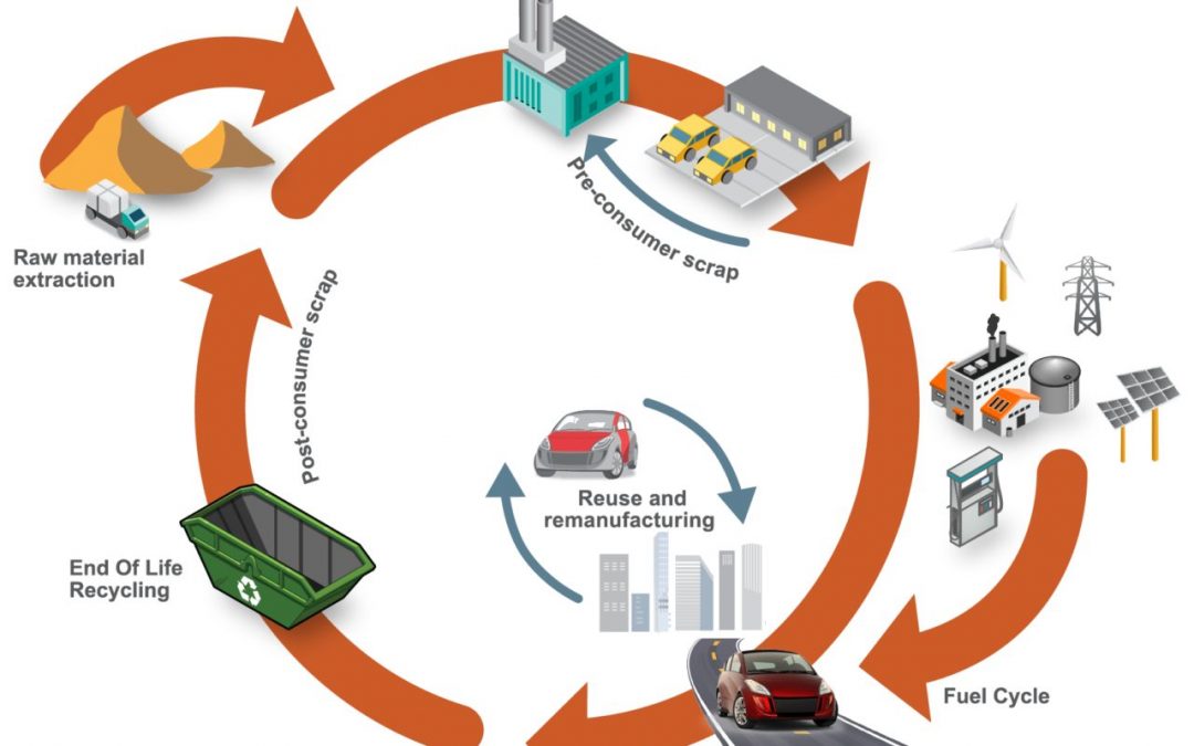
Cradle-to-grave assessments utilize a boundary that includes impacts from the production phase (including raw material extraction and vehicle production), the use phase (including fuel or electricity as well as consumables like tires and fluids) and the end-of-life phase, which could include disposal and/or recyling of the product, as shown in Figure 1. We applied LCA throughout the development of the SEM concept.
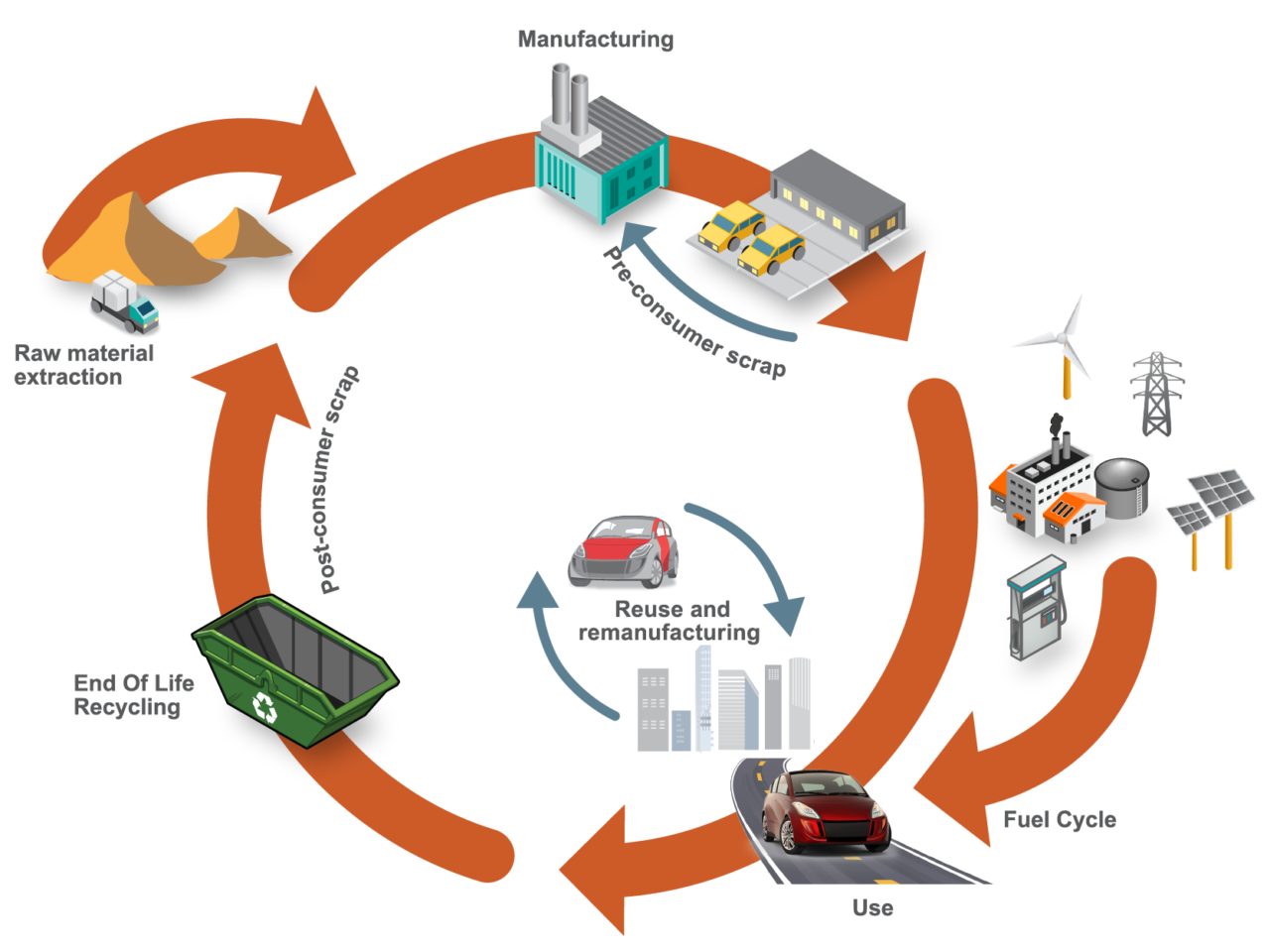
Figure 1. SEQ Figure \* ARABIC 1 Life Cycle Assessment, considering the entire life of the vehicle, from raw material extraction to end of life
LCA can cover a range of environmental impacts; however, for the SEM program, we focused on GHG emissions through the GWP-100 indicator and total energy consumption using Cumulative/Primary Energy Demand and Fossil Energy Consumption indicators.
A key consideration in LCA calculations is establishing an appropriate reference vehicle. For this program, the following criteria was used:
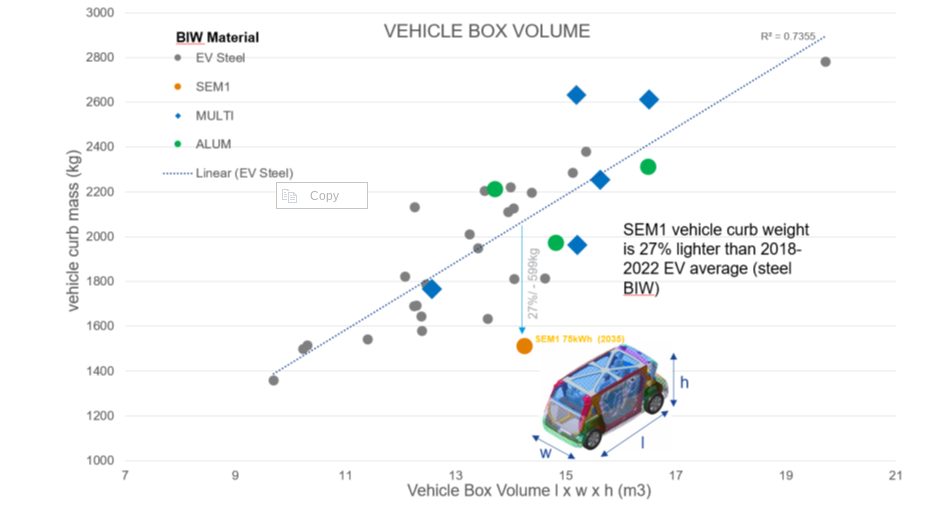
Figure 2. Vehicle curb weight versus box volume comparison. Reference vehicle data; source www.a2mac1.com
SEM vehicle life cycle calculations assume a hypothetical 2030 manufacture and start-of-operation date of 2030 to 2035. We updated the electricity grid supply mix to include the average of the International Energy Agency (IEA) scenario estimates for 2030 and 2040.
Figure 3 below highlights absolute calculated life cycle GHG emissions, in units of kgCO2e/ passengerꞏkilometer studied, with the individual contributions of vehicle manufacturing, vehicle use, and end-of-life phase presented.
The analysis evaluated two reference/baseline conditions and nine SEM sensitivity studies, see Figure 4. These included alternative assumptions on LCA end-of-life modeling methodology, lifetime vehicle activity (and battery lifetime), alternative operational energy consumption sensitivities, sensitivities on the use of ‘green’ steel, and vehicle occupancy rates.
The accompanying pie chart shows the breakdown and contributions to the vehicle manufacture GHG for the baseline SEM scenario (2).
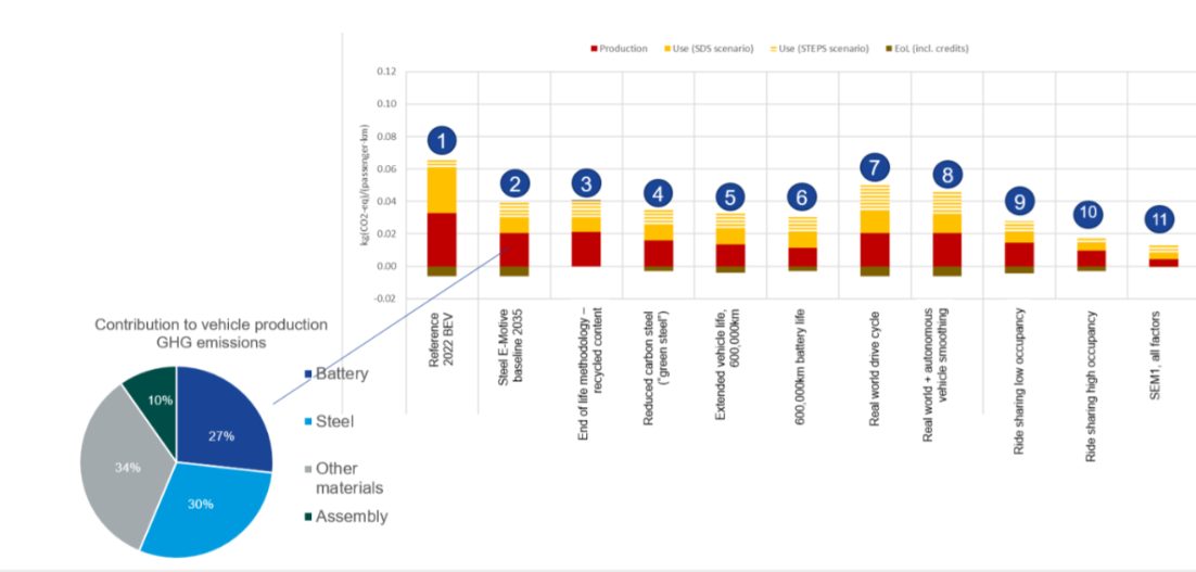
Figure 3. SEQ Figure \* ARABIC 2 life cycle assessment GHG results
Figure 4. Reference/baseline conditions and SEM sensitivity studies
Based on the parameters outlined, applying LCA to SEM concept demonstrated the designs’ potential to reduce lifecycle greenhouse gas emissions by up to 86 percent compared to a present-day battery electric vehicle operating as a taxi.
This potential can be realized by adopting the following measures:
The projected net GHG emissions for the SEM vehicle operating with the flexibilities described above already represent a significant reduction when compared to the current baseline.
Achieving net zero emissions would require additional measures like offsetting manufacturing impacts (e.g., through compensatory credits from atmospheric carbon capture and storage) and transitioning to a 100 percent renewable electricity grid.
Taking a Life Cycle Assessment approach to the SEM concept demonstrates the possibilities for engineering future mobility vehicles that continue to move us closer to a net zero future. For more information about the Steel E-Motive program, download the engineering report here: https://bit.ly/SEM_Eng_Report

Thanks go to Russ Balzer for his contribution of this article to the AHSS Insights blog. As.technical director at WorldAutoSteel, he leads technical programs and oversees the organization’s work in research, modeling, and advocacy for Life Cycle Assessment in the automotive sector. An LCA Certified Professional through the American Center for Life Cycle Assessment (ACLCA), he also acts as the WorldAutoSteel liaison to the worldsteel LCA Expert Group.
The Steel E-Motive battery modules, cooling plates & hoses, electrical connectors, and battery management system are mounted to an AHSS carrier frame. This assembly is then bolted to the body structure. The body in white floor assumes the role of the battery top cover, providing both cost and weight savings; an AHSS bottom cover seals and provides underbody protection.
You can view the details about the SEM1 final battery concept in section 7.3 in the SEM Engineering Report: https://bit.ly/SEM_Eng_Report
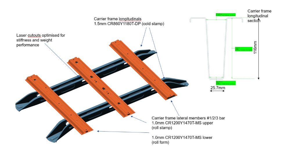
The Steel E-Motive Battery Carrier Frame
The battery carrier frame forms an integral part of the body structure load path. It connects to the front and rear longitudinals and the floor cross members. Two different manufacturing approaches and designs were considered for the longitudinals.
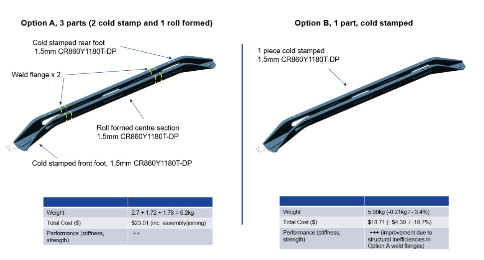
Option A considered a 3-part longitudinal design, with unique cold stampings for the front and rear “feet” and a roll-formed center section. The part integration is accomplished via an overlap weld flange and spot welding. Dual Phase 1180MPa UTS grade AHSS was selected based on the strength required for crash load reaction and enabling a lower 1.5mm gauge thickness. Initially, it was perceived that the roll-formed center section design would enable an overall lower-cost solution.
Option B replaces the 3-piece design with a single, cold-stamped part, again using 1.5mm DP1180 AHSS. The deep draw profile and material’s low ductility presented formability challenges for the cold stamping of the longitudinal. These were overcome by adjustments to the deep draw profile and optimization of the die and stamping parameters.
A comparison of the two designs shows that a small weight saving and a significant cost reduction of $4.30 (18.7%) per longitudinal is achieved with the single cold-stamped design. The vehicle NVH, static stiffness, and crash performance were also calculated to be superior for the integrated design Option B.
Therefore, Option B, provides cost, weight, and performance benefits compared to the multiple part design Option A.
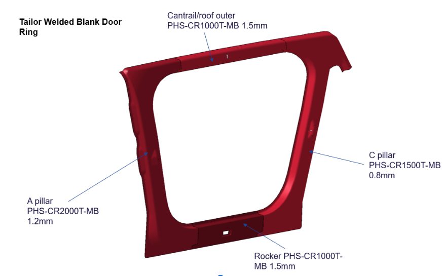
Part integration via laser-welded blanks allows different steel grades, thicknesses, and coating types to be combined into a single blank before the fabrication process. The Steel E-Motive door ring is a hot-formed part consisting of four different blanks with different AHSS grades and thicknesses.
The performance requirements for the specific region determine the grades and thicknesses for each blank. The A-pillar requires very high strength to protect the front occupants in the event of a high-speed frontal or side collision. Lower strengths and grades are required for the rocker, cantrail, and C-pillar parts. The four blanks are cut from the native material grade coil and joined using laser welding to form the single-door ring blank. This then undergoes a hot-forming process to achieve the design door ring shape and the Ultra High-Strength properties of press-hardened steel.
Consolidating four blanks into a single part significantly reduces scrap compared to a single blank part, and simplifies part manufacturing by eliminating other stamping and assembly processes with related cost savings. Higher material utilization means less steel is produced, resulting in lower costs and lower GHG emissions. The laser weld between the blanks helps achieve greater strength and stiffness to spot-welding four individual blanks.
The latest AHSS grades and fabrication processes allow engineers to reduce the number of parts or blanks used in automotive body structures. Several part integration and consolidation processes have been applied and demonstrated in the Steel E-Motive concept. Part consolidation results in lower scrap rates, improved material utilization, reduced part cost, and GHG emissions. The integrated structures also improve overall stiffness and strength performance.

Thanks go to Neil McGregor for his contribution of this article to the AHSS Insights blog. As Chief Engineer, Systems Integration at Ricardo, Neil has extensive knowledge of lightweight, advanced materials across all major vehicle sub-systems and leads the Steel E-Motive vehicle engineering program at Ricardo.