Mild Steels to Advanced Steels: The Phases Make The Difference
Understanding Steel at the Atomic Level
Atoms arrange themselves in three-dimensional patterns called lattices. Think about billiard balls in multiple layers. The balls can be one layer directly above the prior one, or they can be shifted and rest in the crevice formed by adjacent balls in the layer below. The balls are all the same material, but the gap size changes with different arrangements.
A crystal lattice shows atoms in a defined, repetitive pattern. In this simple example the atoms can arrange in a square or triangle pattern. The atom size is the same, but the gap size where small elements like carbon can go depends on the lattice arrangement.
Ferrite and Austenite: The Building Blocks of Steel
This is what happens with steel, which for most automotive grades are at least 97% iron. At temperatures below 725 °C, a maximum of only 0.02% carbon fits in the gap between the iron atoms. This orientation is called ferrite. At higher temperatures, a different atomic orientation is stable, which we call austenite. Up to 2% carbon can fit into this arrangement of atoms. For low-carbon steels under normal conditions, austenite cannot exist at room temperature – when the steel is slowly cooled, it changes from austenite to a combination of ferrite and a mixture of phases called pearlite.
Ferrite: Soft, Ductile, and Low-Strength
100% iron is very soft. Ferrite at room temperature is iron with no more than 80 parts per million carbon. That’s really close to pure iron, so when discussing ferrite, think of something soft, low-strength, and ductile.
Carbon-Manganese Steels: Structural Strength
If additional strength is needed, then more alloying elements must be used in addition to carbon. The next most cost-effective alloying element for strengthening is manganese which produces higher-strength steels called carbon-manganese steels. These grades have limited ductility, especially at higher carbon and manganese contents, so they are used in structural applications that do not need a lot of formability and are therefore also called structural steels (SS).
Microalloying: The Birth of HSLA Steels
Around 1980, steelmakers rolled out a new approach to getting higher strength levels while minimizing the loss of elongation usually seen with higher strengths. They accomplish this by strengthening the ferrite through the addition of very small quantities of titanium, niobium, and vanadium to form carbide and nitride precipitates. These microalloying additions are used in precipitation hardening of the ferrite to create High Strength Low Alloy (HSLA) steels.
Rapid Cooling Enables Martensite Formation
The steels discussed to this point are produced with relatively slow cooling. However, investments by the steel industry resulted in equipment capable of reaching rapid cooling (quenching) rates that allow for production of a very high strength phase called martensite.
Martensite wasn’t commonly found as a microstructural component during most of the history of automotive sheet steels due to the limited number of companies having an annealing line with appropriate quenching capabilities. This started to change around the turn of the millennium when newer annealing lines were installed with capability to achieve complex thermal cycles. This allowed for production of the first generation of Advanced High-Strength Steels (AHSS), including grades that have a microstructure of only martensite.
Dual Phase (DP) Steels: Balancing Strength and Ductility
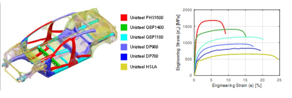
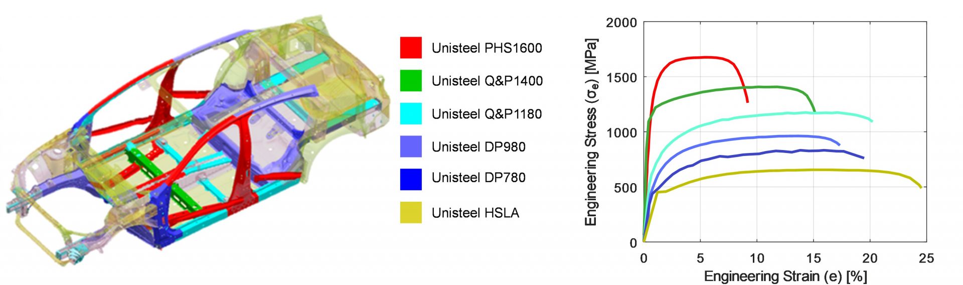
Dual Phase (DP) steels are the most common AHSS. Ferrite and martensite are the two phases in DP steels: ferrite is super-soft and comprises the majority of the microstructure, while martensite is super-hard and takes up 10% (590DP) to 40% (980DP) of the microstructure. The more martensite, the stronger the steel. Since most of the structure is ferrite, these steels have exceptional elongation as measured in a tensile test for the strength level.
TRIP Steels: Transformation-Induced Plasticity
For as good as DP steels are in tensile ductility, TRIP steels are even better. The magic of these grades comes from retained austenite. Austenite is a very ductile phase. What makes this a special phase is that as austenite-containing steels deform, the atoms rearrange and the austenite transforms into martensite, giving the steel enhanced ductility — which researchers state as greater plasticity. Another way of saying that this enhanced ductility comes from austenite transforming to martensite is that these steels have Transformation Induced Plasticity (TRIP).
Ferrite-Bainite and Complex Phase (CP) Steels: Improved Edge Ductility
In both DP and TRIP steels, the large hardness difference between ferrite and martensite leads to crack initiation sites and results in poor cut-edge ductility during stretch flanging. For applications like stretch flanging that need improved cut-edge ductility, one option are the Ferrite-Bainite grades. Bainite is a little lower in strength than martensite but has higher elongation and toughness. Another option are Complex Phase (CP) steels, which have a microstructure of bainite and precipitation-strengthened ferrite, with martensite and retained austenite also present in lower amounts. Lacking soft ferrite, these steels have relatively high yield strength and low elongation as measured in a tensile test, but the bainite leads to exceptional cut-edge ductility as measured in a hole expansion test.
TWIP Steels: Twinning-Induced Plasticity
TWIP steels containing only austenite, and as such are a high-strength, high-ductility steel. These may be written like TRIP steels, but these steels get their plasticity differently. TWIP steels deform by a mechanism known as twinning, so they are described as Twinning Induced Plasticity Steels (TWIP). Unfortunately, achieving the combination of high strength and fantastic formability requires a lot of alloying. This drives up the steelmaking complexity and cost. The alloying elements also make welding much more challenging. TWIP steels are considered second-generation advanced high-strength steels.
3rd Generation AHSS: Tailoring Microstructures for Performance
Nearly all 3rd Generation Advanced High-Strength Steels (3rd Gen AHSS or 3rd Gen) have retained austenite in the microstructure and therefore benefit from a high strength, high ductility combination through the TRIP Effect. The latest annealing lines allow for the creation of an engineered balance and distribution of ferrite, bainite, martensite, and austenite in the microstructure, providing the resultant alloy with properties that can be tailored to address the requirements and challenges of each automotive part.
The Future of Automotive Steels
Together, there are nearly 70 grades of advanced high strength steels available globally. The days of steel being simply a commodity are in the past as it relates to these highly engineered higher strength steels.

Danny Schaeffler is the Metallurgy and Forming Technical Editor of the AHSS Applications Guidelines available from WorldAutoSteel. He is founder and President of Engineering Quality Solutions (EQS). Danny wrote the monthly “Science of Forming” and “Metal Matters” column for Metalforming Magazine, and provides seminars on sheet metal formability for Auto/Steel Partnership and the Precision Metalforming Association. He has written for Stamping Journal and The Fabricator, and has lectured at FabTech. Danny is passionate about training new and experienced employees at manufacturing companies about how sheet metal properties impact their forming success.