Citations
Citations:
Z-18. J. Zhang, C, Lian, and F. Han, “Study on the failure behaviour of Advanced High Strength Steel considering stamping history,” IDDRG 2025, MATEC Web of Conferences Volume 408, 01022 (2025); https://doi.org/10.1051/matecconf/202540801022
![Considerations When Deciding Whether to Cold Form or Hot Form]()
Automakers contemplating whether a part is cold stamped or hot formed must consider numerous ramifications impacting multiple departments. The considerations below relative to cold stamping are applicable to any forming operation occurring at room temperature such as roll forming, hydroforming, or conventional stamping. Similarly, hot stamping refers to any set of operations using Press Hardening Steels (or Press Quenched Steels), including those that are roll formed or fluid-formed.
Equipment
There is a well-established infrastructure for cold stamping. New grades benefit from servo presses, especially for those grades where press force and press energy must be considered. Larger press beds may be necessary to accommodate larger parts. As long as these factors are considered, the existing infrastructure is likely sufficient.
Progressive-die presses have tonnage ratings commonly in the range of 630 to 1250 tons at relatively high stroke rates. Transfer presses, typically ranging from 800 to 2500 tons, operate at relatively lower stroke rates. Power requirements can vary between 75 kW (630 tons) to 350 kW (2500 tons). Recent transfer press installations of approximately 3000 tons capacity allow for processing of an expanded range of higher strength steels.
Hot stamping requires a high-tonnage servo-driven press (approximately 1000 ton force capacity) with a 3 meter by 2 meter bolster, fed by either a roller-hearth furnace more than 30 m long or a multi-chamber furnace. Press hardened steels need to be heated to 900 °C for full austenitization in order to achieve a uniform consistent phase, and this contributes to energy requirements often exceeding 2 MW.
Integrating multiple functions into fewer parts leads to part consolidation. Accommodating large laser-welded parts such as combined front and rear door rings expands the need for even wider furnaces, higher-tonnage presses, and larger bolster dimensions.
Blanking of coils used in the PHS process occurs before the hardening step, so forces are low. Post-hardening trimming usually requires laser cutting, or possibly mechanical cutting if some processing was done to soften the areas of interest.
That contrasts with the blanking and trimming of high strength cold-forming grades. Except for the highest strength cold forming grades, both blanking and trimming tonnage requirements are sufficiently low that conventional mechanical cutting is used on the vast majority of parts. Cut edge quality and uniformity greatly impact the edge stretchability that may lead to unexpected fracture.
Responsibilities
Most cold stamped parts going into a given body-in-white are formed by a tier supplier. In contrast, some automakers create the vast majority of their hot stamped parts in-house, while others rely on their tier suppliers to provide hot stamped components. The number of qualified suppliers capable of producing hot stamped parts is markedly smaller than the number of cold stamping part suppliers.
Hot stamping is more complex than just adding heat to a cold stamping process. Suppliers of cold stamped parts are responsible for forming a dimensionally accurate part, assuming the steel supplier provides sheet metal with the required tensile properties achieved with a targeted microstructure.
Suppliers of hot stamped parts are also responsible for producing a dimensionally accurate part, but have additional responsibility for developing the microstructure and tensile properties of that part from a general steel chemistry typically described as 22MnB5.
Property Development
Independent of which company creates the hot formed part, appropriate quality assurance practices must be in place. With cold stamped parts, steel is produced to meet the minimum requirements for that grade, so routine property testing of the formed part is usually not performed. This is in contrast to hot stamped parts, where the local quench rate has a direct effect on tensile properties after forming. If any portion of the part is not quenched faster than the critical cooling rate, the targeted mechanical properties will not be met and part performance can be compromised. Many companies have a standard practice of testing multiple areas on samples pulled every run. It’s critical that these tested areas are representative of the entire part. For example, on the top of a hat-section profile where there is good contact between the punch and cavity, heat extraction is likely uniform and consistent. However, on the vertical sidewalls, getting sufficient contact between the sheet metal and the tooling is more challenging. As a result, the reduced heat extraction may limit the strengthening effect due to an insufficient quench rate.
Grade Options for Cold Stamped or Hot Formed Steel
There are two types of parts needed for vehicle safety cage applications: those with the highest strength that prevent intrusion, and those with some additional ductility that can help with energy absorption. Each of these types can be achieved via cold stamping or hot stamping.
When it comes to cold stamped parts, many grade options exist at 1000 MPa that also have decent ductility. The advent of the 3rd Generation Advanced High Strength Steels adds to the tally – the stress-strain curve of a 3ʳᵈ Gen QP980 steel is presented in Figure 1. Most of these top out at 1200 MPa, with some companies offering cold-formable Advanced High Strength Steels with 1400 or 1500 MPa tensile strength. The chemistry of AHSS grades is a function of the specific characteristics of each production mill, meaning that OEMs must exercise diligence when changing suppliers.

Figure 1: Stress-strain curve of industrially produced QP980.W-35
Martensitic grades from the steel mill have been in commercial production for many years, with minimum strength levels typically ranging from 900 MPa to 1470 MPa, depending on the grade. These products are typically destined for roll forming, except for possibly those at the lower strengths, due to limited ductility. Until recently, MS1470, a martensitic steel with 1470 MPa minimum tensile strength, was the highest strength cold formable option available. New offerings from global steelmakers now include MS1700, with a 1700 MPa minimum tensile strength, as well as MS 1470 with sufficient ductility to allow for cold stamping. Automakers have deployed these grades in cold stamped applications such as crossmembers and roof reinforcements, with some applications shown in Figure 2.

Figure 2: Cold-Stamped Martensitic Steel with 1500 MPa Tensile Strength used in the Nissan B-Segment Hatchback.K-57
Until these recent developments, hot stamping was the primary option to reach the highest strength levels in part shapes having even mild complexity. Under proper conditions, a chemistry of 22MnB5 could routinely reach a nominal or aim strength of 1500 MPa, which led to this grade being described as PHS1500, CR1500T-MB, or with similar nomenclature. Note that in this terminology, 1500 MPa nominal strength typically corresponds to a minimum strength of 1300 MPa.
The 22MnB5 chemistry is globally available, but the coating approaches discussed below may be company-specific.
Newer PHS options with a modified chemistry and subsequent processing differences can reach nominal strength levels of 2000 MPa. Other options are available with additional ductility at strength levels of 1000 MPa or 1200 MPa. A special class called Press Quenched Steels have even higher ductility with strength as low as 450 MPa.
The spectrum of grades available for cold-stamped and hot formed steel parts allows automakers to fine-tune the crash energy management features within a body structure, contributing to steel’s “infinite tune-ability” capability which gives automotive engineers design flexibility and freedoms not available from other structural materials.
Corrosion Protection
Uncoated versions of a grade must take a different chemistry approach than the hot dip galvanized (GI) or hot dipped galvannealed (HDGA) versions since the hot dip galvanizing process (Figure 3) acts as a heat treatment cycle that changes the properties of the base steel. Steelmakers adjust the base steel chemistry to account for this heat treatment to ensure the resultant properties fall within the grade requirements.

Figure 3: Schematic of a typical hot-dipped galvanizing line with galvanneal capability.
This strategy has limitations as it relates to grades with increasing amounts of martensite in the microstructure. Complex thermal cycles are needed to produce the highly engineered microstructures seen in advanced steels. Above a certain strength level, it is not possible to create a GI or HDGA version of that grade.
For example, when discussing fully martensitic grades from the steel mill, hot dip galvanizing is not an option. If a martensitic grade needs corrosion protection, then electrogalvanizing (Figure 4) is the common approach since an EG coating is applied at ambient temperature, which is low enough to avoid negatively impacting the properties. Automakers might choose to forgo a galvanized coating if the intended application is in a dry area that is not exposed to road salt.

Figure 4: Schematic of an electrogalvanizing line.
For press hardening steels, coatings serve multiple purposes. Without a coating, uncoated steels will oxidize in the austenitizing furnace and develop scale on the surface. During hot stamping, this scale layer limits efficient thermal transfer and may prevent the critical cooling rate from being reached. Furthermore, scale may flake off in the tooling, leading to tool surface damage. Finally, scale remaining after hot stamping is typically removed by shot blasting, an off-line operation that may induce additional issues.
Using a hot dip galvanized steel in a conventional direct press hardening process (blank -> heat -> form/quench) may contribute to liquid metal embrittlement (LME). Getting around this requires either changing the steel chemistry from the conventional 22MnB5 or using an indirect press hardening process that sees the bulk of the part shape formed at ambient temperatures followed by heating and quenching.
Those companies wishing to use the direct press hardening process can use a base steel having an aluminum-silicon (Al-Si) coating, providing that the heating cycle in the austenitizing furnace is such that there is sufficient time for alloying between the coating and the base steel. Welding practices using these coated steels need to account for the aluminum in the coating, but robust practices have been developed and are in widespread use.
Setting Correct Welding Parameters for Resistance Spot Welding
Specific welding parameters need to be developed for each combination of material type and thickness. In general, Press Hardening Steels require more demanding process conditions. One important factor is electrode force, which is typically higher than needed to weld cold formed steels of the same thickness. The actual recommended force depends on the strength level and the thickness of the steel. Of course, strength and thickness affects the welding machine/welding gun force capability requirement.
The welding current level, and more importantly, the current range are both important. The current range is one of the best indicators of welding process robustness, so it is sometimes described as the welding process window. Figure 5 indicates the relative range of current required for spot welding different steel types. A smaller process window may require more frequent weld quality evaluations, such as for adequate weld size, necessitating more frequent corrective actions to address the discovered quality concern.

Figure 5: Relative Current Range (process windows) for Different Steel Types
Effect of Coating Type on Weldability
When resistance spot welding coated steels, the coating must be removed from the weld area during and in the beginning of the weld cycle to allow a steel-to-steel weld to occur. The combination of welding current, weld time, and electrode force are responsible for this coating displacement.
For all coated steels, the ability of the coating to flow is a function of the coating type and properties such as electrical resistivity and melting point, as well as the coating thickness.
Cross sectioned spot welds made on press hardened steel with different coating weights of an Aluminum -Silicon coating is presented in Figure 6. Note the displaced coating at the periphery of weld. Figure 7 shows the difference in current range required to produce acceptable welds associated with these different coating weights. The thicker coating shows a smaller current range. In addition, the press-hardened Al-Si coating has a much higher melting point than the zinc coatings typically found on cold stamped steels, making it more difficult to displace from the weld area.

Figure 6: Aluminum -Silicon coated press hardened steels.O-16
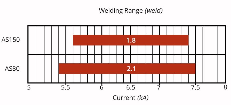
Figure 7: Influence of Aluminum-Silicon coating weight on welding range.O-16
Liquid Metal Embrittlement and Resistance Spot Welding
Cold-formable, coated, Advanced High Strength Steels are widely used in automotive applications. One welding issue these materials encounter is increased hardness in the weld area, that may result in brittle fracture of the weld. Another issue is their sensitivity to Liquid Metal Embrittlement (LME) cracking.
Both issues are discussed in detail in the Joining section of the WorldAutoSteel AHSS Guidelines website and the WorldAutoSteel Phase 2 Report on LME.
Resistance Spot Welding Using Current Pulsation
The most effective solution for these issues is using current pulsation during the welding cycle, schematically described in Figure 8.

Figure 8: Nugget growth differences in Single Pulse vs. Multi-Pulse Welding
Pulsation of the current allows much better control of the heat generation and weld nugget development. Pulsation variables include the number of pulses (typically 2 to 4), current, time for each pulse, and the cool time between the pulses.
Pulsation during Resistance Spot Welding is beneficial for press hardening steels, coated cold stamped steels of all grades, and multi-material stack-ups. Information about multi-sheet, multi-material stack-ups can be – as described in our articles on 3T/4T and 5T Stack-Ups
For more information about PHS grades and processing, see our Press Hardened Steel Primer.
Thanks are given to Eren Billur, Ph.D., Billur MetalForm for his contributions to the Equipment section, as well as many of the webpages relating to Press Hardening Steels at www.AHSSinsights.org.
Blog, homepage-featured-top, main-blog
Equipment, Responsibilities, and Property Development Considerations When Deciding How A Part Gets Formed
Automakers contemplating whether a part is cold stamped or hot formed must consider numerous ramifications impacting multiple departments. Over a series of blogs, we’ll cover some of the considerations that must enter the discussion.
The discussions relative to cold stamping are applicable to any forming operation occurring at room temperature such as roll forming, hydroforming, or conventional stamping. Similarly, hot stamping refers to any set of operations using Press Hardening Steels (or Press Quenched Steels), including those that are roll formed or fluid-formed.
Equipment
There is a well-established infrastructure for cold stamping. New grades benefit from servo presses, especially for those grades where press force and press energy must be considered. Larger press beds may be necessary to accommodate larger parts. As long as these factors are considered, the existing infrastructure is likely sufficient.
Progressive-die presses have tonnage ratings commonly in the range of 630 to 1250 tons at relatively high stroke rates. Transfer presses, typically ranging from 800 to 2500 tons, operate at relatively lower stroke rates. Power requirements can vary between 75 kW (630 tons) to 350 kW (2500 tons). Recent transfer press installations of approximately 3000 tons capacity allow for processing of an expanded range of higher strength steels.
Hot stamping requires a high-tonnage servo-driven press (approximately 1000 ton force capacity) with a 3 meter by 2 meter bolster, fed by either a roller-hearth furnace more than 30 m long or a multi-chamber furnace. Press hardened steels need to be heated to 900 °C for full austenitization in order to achieve a uniform consistent phase, and this contributes to energy requirements often exceeding 2 MW.
Integrating multiple functions into fewer parts leads to part consolidation. Accommodating large laser-welded parts such as combined front and rear door rings expands the need for even wider furnaces, higher-tonnage presses, and larger bolster dimensions.
Blanking of coils used in the PHS process occurs before the hardening step, so forces are low. Post-hardening trimming usually requires laser cutting, or possibly mechanical cutting if some processing was done to soften the areas of interest.
That contrasts with the blanking and trimming of high strength cold-forming grades. Except for the highest strength cold forming grades, both blanking and trimming tonnage requirements are sufficiently low that conventional mechanical cutting is used on the vast majority of parts. Cut edge quality and uniformity greatly impact the edge stretchability that may lead to unexpected fracture.
Responsibilities
Most cold stamped parts going into a given body-in-white are formed by a tier supplier. In contrast, some automakers create the vast majority of their hot stamped parts in-house, while others rely on their tier suppliers to provide hot stamped components. The number of qualified suppliers capable of producing hot stamped parts is markedly smaller than the number of cold stamping part suppliers.
Hot stamping is more complex than just adding heat to a cold stamping process. Suppliers of cold stamped parts are responsible for forming a dimensionally accurate part, assuming the steel supplier provides sheet metal with the required tensile properties achieved with a targeted microstructure.
Suppliers of hot stamped parts are also responsible for producing a dimensionally accurate part, but have additional responsibility for developing the microstructure and tensile properties of that part from a general steel chemistry typically described as 22MnB5.
Property Development
Independent of which company creates the hot formed part, appropriate quality assurance practices must be in place. With cold stamped parts, steel is produced to meet the minimum requirements for that grade, so routine property testing of the formed part is usually not performed. This is in contrast to hot stamped parts, where the local quench rate has a direct effect on tensile properties after forming. If any portion of the part is not quenched faster than the critical cooling rate, the targeted mechanical properties will not be met and part performance can be compromised. Many companies have a standard practice of testing multiple areas on samples pulled every run. It’s critical that these tested areas are representative of the entire part. For example, on the top of a hat-section profile where there is good contact between the punch and cavity, heat extraction is likely uniform and consistent. However, on the vertical sidewalls, getting sufficient contact between the sheet metal and the tooling is more challenging. As a result, the reduced heat extraction may limit the strengthening effect due to an insufficient quench rate.
For more information, see our Press Hardened Steel Primer to learn more about PHS grades and processing!
Thanks are given to Eren Billur, Ph.D., Billur MetalForm for his contributions to the Equipment section, as well as many of the webpages relating to Press Hardening Steels at www.AHSSinsights.org.

Danny Schaeffler is the Metallurgy and Forming Technical Editor of the AHSS Applications Guidelines available from WorldAutoSteel. He is founder and President of Engineering Quality Solutions (EQS). Danny wrote the monthly “Science of Forming” and “Metal Matters” column for Metalforming Magazine, and provides seminars on sheet metal formability for Auto/Steel Partnership and the Precision Metalforming Association. He has written for Stamping Journal and The Fabricator, and has lectured at FabTech. Danny is passionate about training new and experienced employees at manufacturing companies about how sheet metal properties impact their forming success.

Blog, homepage-featured-top, main-blog
Additive Manufacturing (AM) has been associated with the future of manufacturing since its inception. While it does hold several advantages in complex geometries and low-volume production, modern AM systems have yet to make significant in-roads with direct-print parts in industries like automotive manufacturing which are characterized by large volumes of relatively large metal parts. With typical volumes of 1,000+ vehicles per line per day, the required throughput of automotive factory lines outstrips what is available in current AM systems. Further, the large volume of parts allows for rapid amortization of capital equipment such as tools, dies, and stamping presses, circumventing one of the primary advantages of AM: reduced per-piece cost. However, if the focus is shifted from direct-print parts to manufacturing the supporting infrastructure, tools and dies, the economic benefits are regained. Using AM to manufacture forming tools for Advanced High-Strength Steels (AHSS) and Press Hardened Steels (PHS) brings the opportunity for reduced tooling lead-time, reduced tooling cost, and optimization of the tools for weight, strength, and thermal management.
Metal AM: Application in Traditional Forming
While AM enables the flexible production of tools with lead-time reduction and minimal economic impactsG-35, W-29, the production cost for the metal AM tools is significantly higher compared to polymer AM tools and, in some cases, metal tools manufactured by conventional methods. However, cost of the AM tools can be mitigated through topology optimization.A-61 With topology optimization, parts with freeform geometry can be designed that are optimized against a specific objective, for example weight, strength, or stiffness. By reducing overall tool material while maintaining strength, build time on the AM system can be reduced, thereby lowering tool cost.
Potential applications of metal AM forming tools are in prototype construction or small series production, e.g. holders, flanges or medium-size adapters and reinforcing plates.S-74 AM methods have also been utilized for insertion of beads or other geometries for reinforcing/increasing the stiffness of tools.L-36 Cost typically prevents metal AM tools from being used in low-volume cold forming applications where the main tool body is printed, however, high wear components and insert applications have demonstrated significant lead-time savings over traditional manufacturing methods.L-36 Metal AM may be considered in cold forming applications where lead-time is at a premium and cost concerns are secondary.
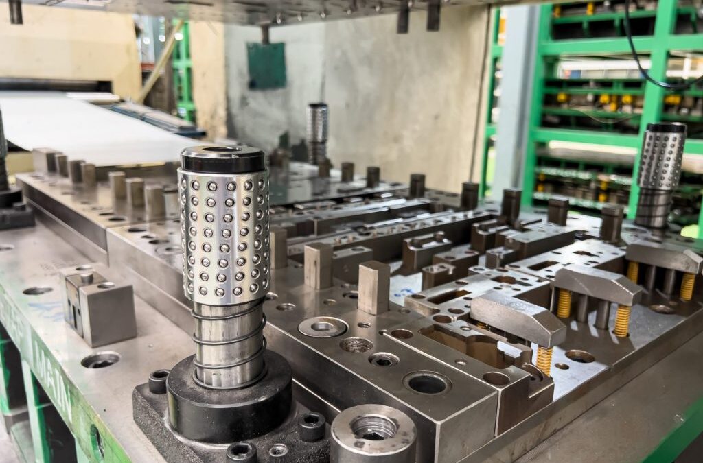
However, in instances where complex internal structures are required, the increased cost of metal AM is outstripped by the benefits it can provide over conventionally manufactured tools. One such example is a metal AM tool for white goods that utilizes high performance stainless steel for the forming surface and less expensive mild steel for the underlying structure. The resulting die, Figure 6, was constructed from less material, reducing overall machining time required to create the finish die surface.P-25
![Figure 6: Metal AM die under construction and after nitriding. [REFERENCE 39]](https://ahssinsights.org/wp-content/uploads/2021/02/Figure_6ab.svg)
Figure 6: Metal AM die under construction and after nitriding.P-25
Metal AM: Application in Hot Stamping
An important advantage of hot forming is that it requires low-forming loads and enables forming parts with high strength and minimal springback. However, the high temperatures required to form the material and the precise cooling required to ensure desirable component properties necessitate advanced tooling designs.
Bulk materials used for fabricating hot stamping dies require special properties. The tool material must exhibit high tensile strength, hardness, good corrosion resistance, a low thermal expansion coefficient, and high thermal conductivity.N-19 Traditionally, casting and machining are used to manufacture hot stamping tools, however, in recent years AM has gained significant traction due to the design freedom that it offers, especially when it comes to fabricating tools with conformal cooling channels. Reducing porosity is one of the primary remaining challenges to maximizing mechanical properties and achieving good build quality in AM components. Conventionally manufactured hot tool steels demonstrate properties of at least 1300 MPa tensile strength, 50 HRC hardness, 18 J of impact toughness and 22 W/mK of thermal conductivity. Selected AM materials should demonstrate at least these properties in order to be considered a reliable alternative.
Hot stamp tooling with conformal cooling channels has been demonstrated with both Directed Energy Deposition (DED) and and Powder-Bed Fusion (PBF) AM processes. With DED processes, it is possible to attain minimum channel diameters as low as 3 mm and a minimum wall thicknesses of 2 mm. Unlike drilling straight holes, as done with traditional tool manufacturing, it is possible to design and fabricate complex cooling channels inside the die that results in homogeneous temperature distribution within the tool and the stamped parts. The improved temperature distribution leads to lower cycle times in hot stamping and subsequent improvement in process efficiency, reducing overall production costs. DED also has been combined with subtractive processes to create a hybrid manufacturing process.C-21 One example includes hot stamping dies manufactured by machining and additively building inserts with conformal cooling ducts.M-35 As a result, the additively manufactured channels cooled six times faster than the conventional drilled channels. In another example, manufactured injection molds with conformal cooling ducts by combining direct metal rapid tooling and machining.A-62
PBF processes are also used to integrate conformal cooling channels into forging dies and hot stamping tools. Regardless of the AM method, development of the internal network channels can be aided by topology optimization, a tool that offers great flexibility in designing non-intuitive, novel, and complex parts with high performance at reduced material cost.G-36 In addition to optimizing for mechanical objectives, topology optimization can also be defined such that it designs products considering performance criteria across multiple domains such as thermal and mechanical. Such multi-objective topology optimization is a powerful tool in designing metal AM tooling that takes advantage of the optimized thermal and mechanical performance made possible through AM processes.
This is an excerpt of a full Guidelines article entitled, “Additive Manufacturing for Sheet Metal Forming Tools,” which is based on a project conducted in partnership between Honda Development & Manufacturing of America, LLC and The Ohio State University. This excerpt focuses on metal AM in traditional forming and hot stamping, while the full article surveys the use of polymer and metal AM for forming tools and discusses the benefits and challenges with respect to their use in manufacturing AHSS and PHS sheet metal components. Be sure to read the full article for the much more detail.
Many thanks are given the team who contributed the Additive Manufacturing article, from which this blog was excerpted.
 |
Ryan Hahnlen, Honda Development & Manufacturing of America, LLC, Raymond, OH |
|
Ben Hoffman, Honda Development & Manufacturing of America, LLC, Raymond, OH |
|
Madhura Athale, Integrated Systems Engineering Department at Ohio State University, Columbus, OH |
|
Taejoon Park, Integrated Systems Engineering Department at Ohio State University, Columbus, OH |
 |
Farhang Pourboghrat, Integrated Systems Engineering Department at Ohio State University, Columbus, OH |
|
|
![Considerations When Deciding Whether to Cold Form or Hot Form]()
Additive Manufacturing
Additive Manufacturing (AM) has been associated with the future of manufacturing since its inception. While it does hold several advantages in complex geometries and low-volume production, modern AM systems have yet to make significant in-roads with direct-print parts in industries like automotive manufacturing which are characterized by large volumes of relatively large metal parts. With typical volumes of 1,000+ vehicles per line per day, the required throughput of automotive factory lines outstrips what is available in current AM systems. Further, the large volume of parts allows for rapid amortization of capital equipment such as tools, dies, and stamping presses, circumventing one of the primary advantages of AM: reduced per-piece cost. However, if the focus is shifted from direct-print parts to manufacturing the supporting infrastructure, tools and dies, the economic benefits are regained. Stamping tools for Advanced High-Strength Steels (AHSS) and Press Hardened Steels (PHS) feature complex geometries and require long lead times for development and manufacturing. Using AM to manufacture forming tools for AHSS and PHS brings the opportunity for reduced tooling lead-time, reduced tooling cost, and optimization of the tools for weight, strength, and thermal management.
In this article, based on a project conducted in partnership between Honda Development & Manufacturing of America, LLC and The Ohio State University, we will survey the use of polymer and metal AM for forming tools and discuss the benefits and challenges with respect to their use in manufacturing AHSS and PHS sheet metal components.

Figure 1: Relative cost of components made via AM and traditional manufacturing methods.
The benefits of using polymer AM dies lie within low volume production such as vehicle prototyping and spare part manufacturing where the cost of traditional tooling results in high per-piece prices.S-74, H-38 One of the most common methods of polymer AM die fabrication is Fused Filament Fabrication (FFF), also known as Fused Deposition Modeling (FDM). In the FFF process, a thermoplastic filament is fed through a heated extruder nozzle to deposit material using a CNC stage. The third dimension of the build is achieved by depositing a new layer of material on previously deposited layers. The wide variety of applicable feedstock materials and relatively simple systems make FFF a widely used modality. FFF materials relevant to forming AHSS include polylactic acid (PLA), acrylonitrile butadiene styrene (ABS), polyether ether ketone (PEEK) and polycarbonate (PC) among many others. Various additives used in FFF polymers address issues such as temperature resistance, strength, and stiffness. The most common additives for enhancing mechanical properties are carbon and glass fiber. With notable exceptions, build volumes for commercial FFF systems is typically limited, requiring full-sized dies to be pieced together from multiple builds.
Big Area Additive Manufacturing (BAAM) has also been investigated for use in creating polymer AM forming dies.H-39 BAAM is similar to FFF in that heated thermoplastic is extruded through a nozzle and positioned layer-by-layer via a CNC system. Rather than a spool of filament, BAAM uses thermoplastic pellets heated and deposited through an extruder similar to those used in injection molding. As a result, the applicable material base in BAAM is much wider, including polymers with modifiers and fillers not available in commercial FFF systems. A second advantage of BAAM systems is the build envelop of 6 m x 2.4 m x 1.8 m (20 ft x 8 ft x 6 ft)S-75, capable of printing production-scale automotive dies in a single piece.

Figure 2: Interior build volume of a BAAM system at the Oak Ridge National Lab Manufacturing Demonstration Facility.S-75
Polymer AM: Application in Hydroforming
Hydroforming of sheet metals is the process of forming metal components using a liquid medium at high pressure to force a metal blank into a female die. There are multiple variations of the hydroforming process, in which some processes apply the liquid medium directly to a sheet metal component, and others, such as bladder hydroforming, contain the liquid medium in a rubber bladder, using increased liquid pressure to expand the bladder to act as the upper die, forming the sheet metal part.
Hydroforming has merit as a prototyping method, as the process typically requires only one die, reducing the tooling investment significantly. Although hydroforming is generally a slower manufacturing process, this is not an issue when low volumes of parts are needed, such as in prototyping. There are concerns in utilizing the hydroforming process for prototypes when a traditional stamping process will be used for high volume production. Hydroforming has a slow and steady increase in pressure put on the sheet metal part and tool, which leads to a more uniform pressure distribution during the forming operation. This uniform pressure distribution can allow part shapes to be formed that would tear or wrinkle when attempted with traditional forming methods, leading to false impression of part formability. The uniform pressure distribution also leads to a more uniform thickness distribution across the sheet metal part, along with uniform strain-hardening and a reduction in spring back in the forming process.K-31 These characteristics result in sheet metal parts that have different properties than traditionally formed parts, and may perform better in a crash or fatigue test, giving an inaccurate representation of how a stamped part would perform. Since the hydroforming process cannot keep up with most high volume automotive production demands, the use of hydroforming is limited to prototypes, however, the prototypes may not match the performance of the final production part. Though there is cost savings in the hard tooling and process for prototyping, it may not be an acceptable prototype method for crash or other critical components where part strain history is important.
Polymer AM tooling can be combined with hydroforming to further reduce prototype costs in development. Since hydroforming has a slower, more uniform pressure distribution across the tool, there are no localized high strain areas that can cause cracks and deformation in plastic printed tools. By virtue of the hydroforming process requiring less tooling and the use polymer AM for the solitary tool, a significant reduction in cost can be achieved compared to machining a traditional prototype tool set. The amount of savings per part is dependent on tool geometry. Generally, higher part complexity, and therefore higher tool surface complexity, yields higher the potential savings when manufacturing tooling via AM. The increased savings is primarily due to a reduction in the time required to program, set-up, and machine traditional tooling, where AM tools require only a few minutes of setup and toolpath creation before printing. It has also been shown that printed tools can be utilized directly from the printer, with minimal post processing, further reducing the manpower needed to produce the tools. Finally, because printed tools are lightweight, there is less labor required to set the tooling up in the hydroforming press.H-40, F-29, A-59

Figure 3: Polymer AM tooling for hydroforming application.
There are multiple examples in industry where 3D Printed plastic tooling has been used with the hydroforming process to reduced costs and lead-time. In one example from an AM system OEM shows a printed tool that formed 400 parts, without noticeable cracking or deformation of the tool. This tool reduced the tool lead-time by 80% and cost by 70% when compared to CNC Machined tool.H-40, F-29, A-59 These savings were achieved by the ‘lights-out and hands-off manufacturing’ process that AM provides, compared to the labor intensive and skilled work required for the CNC programming and machining.
It has been shown that the combination of sheet metal hydroforming, along with 3D Printed plastic tooling, can allow a significant reduction in cost and investment for prototype sheet metal production. Although the hydroforming process allows for a lower cost part than traditional sheet metal stamping, care must be taken when selecting this process, as the final part may perform differently than a stamped part during crash or fatigue testing. If the final production process requires stamping due to process speed, then hydroforming for prototypes may mislead the designers and engineers about the viability of that part in production. Adding the use of polymer AM tools can lead to a higher reduction in prototype costs, but more investigation is needed in the area of process simulation to better understand long term viability of the printed tools.
Polymer AM: Application in Traditional Forming
In contrast to hydroforming, traditional cold forming of sheet metal components involves the use of opposing matched tooling. Further variations include crash forming and draw forming, with the difference being a sheet metal binder used to restrict the free draw-in of the sheet metal to promote in-plane stretching. The benefit of using traditional forming over hydroforming is the process time. Large capacity presses enable rapid closing of die sets and forming of sheet metal without needing to wait for fluid pressurization required for hydroforming AHSS. As a result, mechanical and servo-mechanical presses are commonly utilized in production of automotive components. By creating matched die sets from AM for prototype and low volume operations, the forming processes and stress-strain states of the resulting parts closely resemble those manufactured via existing mass production methods. Polymer AM tooling has been investigated for both crash formingH-38, S-76 and draw formingH-39, J-18 using a variety of AM systems and materials.
The use of polymer feedstock makes polymer AM components significantly less expensive than those made on metal AM systems. If the tool set design is carefully considered, polymer AM tools have been shown to be less expensive than traditional hard metal tools. Tools manufactured using FFF fulfil the technical requirements for small series forming runs and are 56 – 63 % less expensive than conventional metal tools made with 42CrMo4S-76 while metal forming tools constructed via BAAM can save as much as 45% of the cost of traditionally manufactured tool steel dies.H-39 This approach requires careful consideration of the AM tool set design, including the use of a mixed material approach using traditional metal tools for less geometrically complex components like blank holders, and reserving AM for tools with more complex geometry.J-18 If AM build resolution is sufficiently fine, finish machining may not be necessary, saving additional process cost. However, print time and resolution are inversely related: builds with fine resolution will take longer to print and have a higher cost in terms of AM machine time while coarse resolution builds such as those made on BAAM systems will have shorter print times but require CNC machining to achieve the final geometry. An additional cost saving measure can be achieved by using a sparse in-fill, or eliminating in-fill entirely on the AM build and then backfilling with an inexpensive material, such as epoxy or concrete, to regain tool rigidity and strength. This approach minimizes AM machine time and material, further reducing the cost of the printed die set.H-39
The largest concern with polymer tooling is the decreased rigidity of the dies. While engineering polymers have been shown to have sufficient strength for AHSS forming, even high stiffness polymers such as carbon fiber filled ABS and glass fiber filled PC have elastic moduli two orders of magnitude less than that of steel used for traditional forming tools.H-39 The lower modulus of polymer materials compared to steels results in higher tool deformations resulting in greater springback in the stamped parts. Die deflection is further exacerbated by measures used to reduce cost and build time, namely the reduction or elimination of the AM infill. However, if the infill is reduced and substituted for a higher stiffness backfill or metal inclusions, the overall stiffness of the AM die can be increased beyond that possible with a solid polymer print while reducing cost.H-39, S-76
Another consequence of the lower polymer modulus is tool wear with repeated forming cycles. Wear is divided into two primary categories: abrasive and adhesive wear. In considering polymers tools for sheet metal forming, abrasion is principally responsible for friction and wear.L-34 Abrasive wear occurs when hard particles at the interface between two surfaces press into or move against the surfaces under pressure, causing local deformation and material loss at the surface. Various tests such as the pin-on-disk test or draw bending test are used to calibrate the friction and wear behavior of polymer-metal material pairs. Accurate calibration of friction and wear are necessary for the correct prediction of tool life, which is an important design factor and economic consideration for polymer AM tooling.
Polymer AM dies have been demonstrated on several steel grades including DC01, CR3, CR240LA, and DP590 in gauges up to 1.6 mm thick. Studies have investigated progressive tool wear, formed part accuracy, and best design practices when using AM tooling. In forming steel sheet metal, polymer AM dies and the resulting parts are shown to have significant geometric deviations when features have radii smaller than 1.5 mm, with a majority of the die deformation occurring as the first part is formed.S-76 However, features with larger radii, especially when coupled with carbon fiber or glass fiber filled polymers, have been shown to have sub-millimeter deviation after trial runs of 100 parts.H-39
![Figure 4: AM GF-PC die and punch with DP590 formed part. [REFERENCE 3]](https://ahssinsights.org/wp-content/uploads/2021/02/Figure_4abc.svg)
Figure 4: AM GF-PC die and punch with DP590 formed part.H-39
While FE simulations are used to assess the feasibility of any new forming process, this is especially important with polymer tools. Simulating the forming processes with conventional steel tools is easier as they are usually modeled as rigid parts. Since polymer tools are much less stiff and generally weaker than their tool steel counterparts, it is important to estimate the stress levels and deflections of these tools. AM polymer parts have anisotropic mechanical properties resulting from their layered manufacturing process, infill pattern, and presence of reinforcements. These tools often have small internal voids which can contribute to the asymmetry of mechanical properties in tension and compression. It is crucial to characterize these materials using tension, compression, and shear tests in various orientations, to get accurate simulation results.D-26, C-18 FE simulations have also been used to predict the failure of polymer AM structures as a result of accumulated internal damageT-30, P-24 which is important to understanding polymer die life from a structural perspective.
![Figure 5: FEA of a polymer AM die set showing tool stresses during forming. [REFERENCE 3]](https://ahssinsights.org/wp-content/uploads/2021/02/Figure_5.svg)
Figure 5: FEA of a polymer AM die set showing tool stresses during forming.H-39
Applicable metal AM technologies for metal forming tools can be broadly classified into Directed Energy Deposition (DED) and Powder-Bed Fusion (PBF) processes.A-60, K-32 In DED process, thermal energy is directly focused on a small region to melt metallic powder or wire materials.K-33, S-77 After movement of the thermal energy source, the melted material is deposited, fused into the melted substrate, and solidifies.G-34 DED includes Laser Engineered Net Shaping (LENS), Direct Metal Deposition (DMD), Laser Metal Deposition (LMD), and Shaped Metal Deposition (SMD) systems.K-32 DED systems have material deposition rates in excess of 1200 cm3/h, but typically have a higher surface roughness, requiring post-process machining.
PBF processes differ from DED processes in that the metal powder feed stock is placed in a horizontal bed and selectively consolidated via a laser or electron beam. In between each successive layer, more powder is deposited to be melted or sintered to form the next layer.B-39, N-17 PBF can manufacture complex shapes with high accuracy (± 0.02 mm).N-18, S-78 However, this process is often slower than DED with deposition rates up to 105 cm3/h, so it is mainly used for small components.N-18
While AM enables the flexible production of tools with lead-time reduction and minimal economic impactsG-35, W-29, the production cost for the metal AM tools is significantly higher compared to polymer AM tools and, in some cases, metal tools manufactured by conventional methods. However, cost of the AM tools can be mitigated through topology optimization.A-61 With topology optimization, parts with freeform geometry can be designed that are optimized against a specific objective, for example weight, strength, or stiffness. By reducing overall tool material while maintaining strength, build time on the AM system can be reduced, thereby lowering tool cost.
Unlike polymer AM parts, metal AM parts typically require suitable post-processing operations to attain the proper shape and surface finish.M-33, T-31 The added machining processes increase both tool lead-time and cost.
Other problems may arise in metal AM tools include thermal deformation, processing defects, and reduced fracture toughness.K-32 The thermal deformation results from the scanning heat source locally melting material and allowing it to cool, such as in DED and PBD processes. As each region solidifies, it continues to cool and contract, resulting in thermal stresses that increase as the build volume increases.K-34, M-34 The deformation can be mitigated through design of the component itself and placement of support structures. Processing defects in AM builds impact bulk mechanical properties such as tensile strength and fracture toughness.L-35, V-14 These defects are heterogeneously distributed within the AM build, resulting in lower fracture toughness and providing a propagation path for cracks.S-79, J-19 Residual stresses within the metal AM tools also adversely affect the fracture toughnessC-19, though this can be overcome with post-build heat treatments.
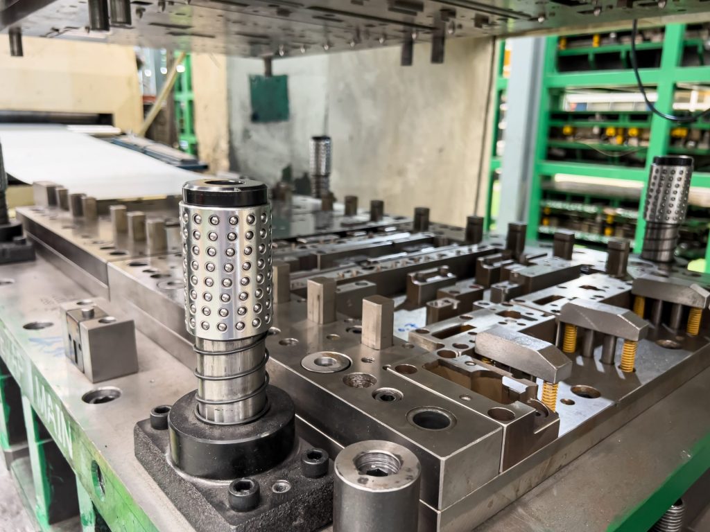
Potential applications of metal AM forming tools are in prototype construction or small series production, e.g. holders, flanges or medium-size adapters and reinforcing plates.S-74 AM methods have also been utilized for insertion of beads or other geometries for reinforcing/increasing the stiffness of tools.L-36 Cost typically prevents metal AM tools from being used in low-volume cold forming applications where the main tool body is printed, however, high wear components and insert applications have demonstrated significant lead-time savings over traditional manufacturing methods.L-36 Metal AM may be considered in cold forming applications where lead-time is at a premium and cost concerns are secondary. However, in instances where complex internal structures are required, the increased cost of metal AM is outstripped by the benefits it can provide over conventionally manufactured tools. One such example is a metal AM tool for white goods that utilizes high performance stainless steel for the forming surface and less expensive mild steel for the underlying structure. The resulting die, Figure 6, was constructed from less material, reducing overall machining time required to create the finish die surface.P-25
Figure 6: Metal AM die under construction and after nitriding.P-25
Hot stamping is an established process for fabricating structural parts with advanced steel and aluminum alloys.C-20 An important advantage of hot forming is that it requires low-forming loads and enables forming parts with high strength and minimal springback. However, the high temperatures required to form the material and the precise cooling required to ensure desirable component properties necessitate advanced tooling designs.
Bulk materials used for fabricating hot stamping dies require special properties. The tool material must exhibit high tensile strength, hardness, good corrosion resistance, a low thermal expansion coefficient, and high thermal conductivity.N-19 Traditionally, casting and machining are used to manufacture hot stamping tools, however, in recent years AM has gained significant traction due to the design freedom that it offers, especially when it comes to fabricating tools with conformal cooling channels. Reducing porosity is one of the primary remaining challenges to maximizing mechanical properties and achieving good build quality in AM components. Conventionally manufactured hot tool steels demonstrate properties of at least 1300 MPa tensile strength, 50 HRC hardness, 18 J of impact toughness and 22 W/mK of thermal conductivity. Selected AM materials should demonstrate at least these properties in order to be considered a reliable alternative.
When forming PHS, the steel sheet is heated to 900 °C – 950 °C and then transferred to an internally cooled stamping die where it is simultaneously stamped and quenched. The austenite into martensite transformation occurs when the sheet is cooled to a temperature in the range of 420 °C – 280 °C. To accomplish this transformation, the dies must be actively cooled at a minimum cooling rate of 27 °C per second.E-7 Maintaining tool temperatures below 200 °C helps ensure the proper cooling of the blank, resulting in high part strength, and prolongs the lifespan of the tools.H-41 To achieve this, the design of the cooling channels is critical, as improper channel design may cause the temperature of the tool to increase during the stamping process, causing insufficient quenching and reducing properties of the final product. Moreover, if cooling is not consistent throughout the die, non-homogeneous surface temperature may result in hot spots which interfere with proper quenching, creating non-homogenous material properties in the finished part. Metal AM processes provide the opportunity to have arbitrary cooling channel networks not possible with traditional machining methods, resulting in more efficient cooling and better end-part performance.
Hot stamp tooling with conformal cooling channels has been demonstrated with both DED and PBF AM processes. With DED processes, it is possible to attain minimum channel diameters as low as 3 mm and a minimum wall thicknesses of 2 mm. Unlike drilling straight holes, as done with traditional tool manufacturing, it is possible to design and fabricate complex cooling channels inside the die that results in homogeneous temperature distribution within the tool and the stamped parts. The improved temperature distribution leads to lower cycle times in hot stamping and subsequent improvement in process efficiency, reducing overall production costs. DED has also been combined with subtractive processes to create a hybrid manufacturing process.C-21 One example includes hot stamping dies manufactured by machining and additively building inserts with conformal cooling ducts.M-35 As a result, the additively manufactured channels cooled six times faster than the conventional drilled channels. In another example, manufactured injection molds with conformal cooling ducts by combining direct metal rapid tooling and machining.A-62
PBF processes are also used to integrate conformal cooling channels into forging dies and hot stamping tools. PBFA-63 has over 50 different process parameters that can impact the quality of the final part, creating a significant challenge in understanding process physics and developing an effective build strategy.S-51 Unlike other processes, PBF can produce lattice structures and conformal cooling channels with a high level of dimensional accuracy and surface roughness .
Regardless of the AM method, development of the internal network channels can be aided by topology optimization, a tool that offers great flexibility in designing non-intuitive, novel, and complex parts with high performance at reduced material cost.G-36 In addition to optimizing for mechanical objectives, topology optimization can also be defined such that it designs products considering performance criteria across multiple domains such as thermal and mechanical. Such multi-objective topology optimization is a powerful tool in designing metal AM tooling that takes advantage of the optimized thermal and mechanical performance made possible through AM processes.
Summary
The continued maturation of AM has enabled low-cost, rapid, and highly capable tooling for AHSS and PHS forming applications. Depending on the specific application needs and volume, there are several developed AM technologies that can provide economical forming applications in both low and high volume production. Through careful material selection, tool design, and simulation, AM tooling can become competitive with traditionally machined tooling in meeting the metal forming needs of the automotive industry.
Thanks are given the team who contributed this article:
|
Ryan Hahnlen, Honda Development & Manufacturing of America, LLC, Raymond, OH |
|
Ben Hoffman, Honda Development & Manufacturing of America, LLC, Raymond, OH |
|
Madhura Athale, Integrated Systems Engineering Department at Ohio State University, Columbus, OH |
|
Taejoon Park, Integrated Systems Engineering Department at Ohio State University, Columbus, OH |
|
Farhang Pourboghrat, Integrated Systems Engineering Department at Ohio State University, Columbus, OH |
|
|
Back To Top


