This article explores the challenges of liquid metal embrittlement (LME) in resistance spot welding (RSW) of automotive components, particularly focusing on a component-scale S-Rail made from advanced high-strength steel (AHSS). The study aims to identify the occurrence of LME during the welding process and to propose effective strategies for its mitigation. This article is an excerpt from the “LME component study” conducted by WorldAutoSteel. The full study can be downloaded here.
Experimental and Simulative Setup
The experiments utilized an electrogalvanized RA1180 AHSS joined to hot-dip galvanized mild steel. Two stack-up configurations were tested: similar (both sheets made of RA1180) and dissimilar (RA1180 on top of mild steel). The resistance spot welding process was monitored using sensors to record current, voltage, and force. Different welding parameters, such as hold time and electrode geometry, were varied to observe their effects on LME.
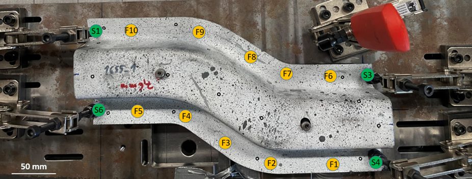
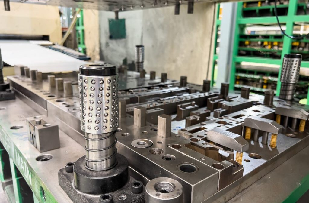
Figure 1: Top-view of the S-Rail component during welding. The clamping points S1-S4 as well as the welding points F1-F10 are highlighted.
A simulation-based risk criterion for LME was established based on local stresses in the components. Both experimental and numerical analyses were conducted to assess the influence of various parameters on LME formation. Specifically, the study evaluated how springback, a phenomenon occurring during deep drawing, affects LME risk. Correct clamping can effectively suppress springback, consequently reducing LME occurrences.
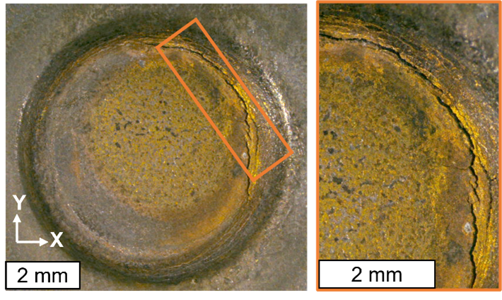
Figure 2: Experimentally observed cracks with 5° tilted electrodes and doubled welding time of 760 ms.
Findings
Influence of Springback: Springback contributed to LME formation. When clamping was employed to counteract springback, LME was effectively eliminated from the welded samples.
Electrode Geometry and Hold Time: Adjustments to the electrode geometry and increasing hold time after welding further mitigated LME risks. Specifically, larger electrode tip diameters and longer hold times reduced the likelihood of cracks.
Material Stack-up Effects: The experiments indicated that the configuration of the material stack-up influenced LME occurrences. Only stack-ups with thick joining partners showed occurrence of LME in the trials.
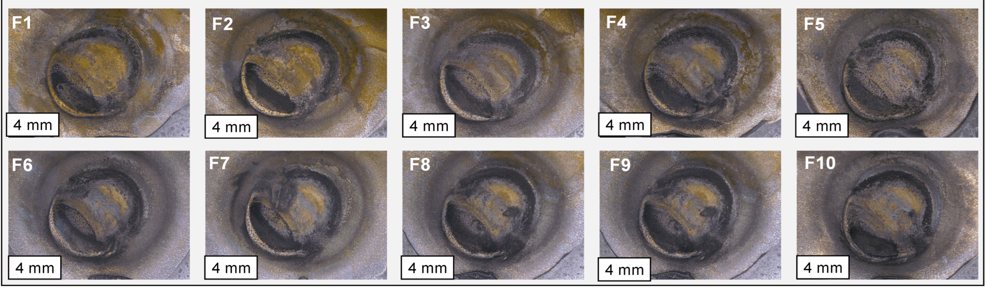
Figure 3: All 10 resistance spot welds on the S-rail are crack-free after optimizing either springback, electrode working plane diameter or post-weld hold time
Simulation Results
Finite element simulations were used to evaluate the risk of LME by analyzing local stresses and temperature distributions during welding. The results showed that the springback-affected samples presented a higher LME risk compared to idealized, straightened models. This finding aligns with experimental observations that cracks occurred where excessive springback influenced the welding process. Even in the case of springback, LME could be effectively prevented by using electrode caps with larger working planes as well as slightly extending the hold time after welding.
The developed simulation approach allows comparing the LME conditions for different welding setups and can therefore optimize the LME occurrence for geometry, material and welding conditions.
Conclusion
Effective mitigation strategies, such as clamping to suppress springback and adjustments in welding parameters, can prevent LME on a component-scale. It can also be highlighted that today’s AHSS grades are far less sensitive to LME by-default so that few RSW joints in a whole body-in-white are at all susceptible for cracking: To produce cracks for this study, welding parameters with increased energy input had to be used; no LME was observed under “standard” industrial conditions.
Automakers contemplating whether a part is cold stamped or hot formed must consider numerous ramifications impacting multiple departments. The considerations below relative to cold stamping are applicable to any forming operation occurring at room temperature such as roll forming, hydroforming, or conventional stamping. Similarly, hot stamping refers to any set of operations using Press Hardening Steels (or Press Quenched Steels), including those that are roll formed or fluid-formed.
Equipment
There is a well-established infrastructure for cold stamping. New grades benefit from servo presses, especially for those grades where press force and press energy must be considered. Larger press beds may be necessary to accommodate larger parts. As long as these factors are considered, the existing infrastructure is likely sufficient.
Progressive-die presses have tonnage ratings commonly in the range of 630 to 1250 tons at relatively high stroke rates. Transfer presses, typically ranging from 800 to 2500 tons, operate at relatively lower stroke rates. Power requirements can vary between 75 kW (630 tons) to 350 kW (2500 tons). Recent transfer press installations of approximately 3000 tons capacity allow for processing of an expanded range of higher strength steels.
Hot stamping requires a high-tonnage servo-driven press (approximately 1000 ton force capacity) with a 3 meter by 2 meter bolster, fed by either a roller-hearth furnace more than 30 m long or a multi-chamber furnace. Press hardened steels need to be heated to 900 °C for full austenitization in order to achieve a uniform consistent phase, and this contributes to energy requirements often exceeding 2 MW.
Integrating multiple functions into fewer parts leads to part consolidation. Accommodating large laser-welded parts such as combined front and rear door rings expands the need for even wider furnaces, higher-tonnage presses, and larger bolster dimensions.
Blanking of coils used in the PHS process occurs before the hardening step, so forces are low. Post-hardening trimming usually requires laser cutting, or possibly mechanical cutting if some processing was done to soften the areas of interest.
That contrasts with the blanking and trimming of high strength cold-forming grades. Except for the highest strength cold forming grades, both blanking and trimming tonnage requirements are sufficiently low that conventional mechanical cutting is used on the vast majority of parts. Cut edge quality and uniformity greatly impact the edge stretchability that may lead to unexpected fracture.
Responsibilities
Most cold stamped parts going into a given body-in-white are formed by a tier supplier. In contrast, some automakers create the vast majority of their hot stamped parts in-house, while others rely on their tier suppliers to provide hot stamped components. The number of qualified suppliers capable of producing hot stamped parts is markedly smaller than the number of cold stamping part suppliers.
Hot stamping is more complex than just adding heat to a cold stamping process. Suppliers of cold stamped parts are responsible for forming a dimensionally accurate part, assuming the steel supplier provides sheet metal with the required tensile properties achieved with a targeted microstructure.
Suppliers of hot stamped parts are also responsible for producing a dimensionally accurate part, but have additional responsibility for developing the microstructure and tensile properties of that part from a general steel chemistry typically described as 22MnB5.
Property Development
Independent of which company creates the hot formed part, appropriate quality assurance practices must be in place. With cold stamped parts, steel is produced to meet the minimum requirements for that grade, so routine property testing of the formed part is usually not performed. This is in contrast to hot stamped parts, where the local quench rate has a direct effect on tensile properties after forming. If any portion of the part is not quenched faster than the critical cooling rate, the targeted mechanical properties will not be met and part performance can be compromised. Many companies have a standard practice of testing multiple areas on samples pulled every run. It’s critical that these tested areas are representative of the entire part. For example, on the top of a hat-section profile where there is good contact between the punch and cavity, heat extraction is likely uniform and consistent. However, on the vertical sidewalls, getting sufficient contact between the sheet metal and the tooling is more challenging. As a result, the reduced heat extraction may limit the strengthening effect due to an insufficient quench rate.
Grade Options for Cold Stamped or Hot Formed Steel
There are two types of parts needed for vehicle safety cage applications: those with the highest strength that prevent intrusion, and those with some additional ductility that can help with energy absorption. Each of these types can be achieved via cold stamping or hot stamping.
When it comes to cold stamped parts, many grade options exist at 1000 MPa that also have decent ductility. The advent of the 3rd Generation Advanced High Strength Steels adds to the tally – the stress-strain curve of a 3ʳᵈ Gen QP980 steel is presented in Figure 1. Most of these top out at 1200 MPa, with some companies offering cold-formable Advanced High Strength Steels with 1400 or 1500 MPa tensile strength. The chemistry of AHSS grades is a function of the specific characteristics of each production mill, meaning that OEMs must exercise diligence when changing suppliers.
Figure 1: Stress-strain curve of industrially produced QP980.W-35
Martensitic grades from the steel mill have been in commercial production for many years, with minimum strength levels typically ranging from 900 MPa to 1470 MPa, depending on the grade. These products are typically destined for roll forming, except for possibly those at the lower strengths, due to limited ductility. Until recently, MS1470, a martensitic steel with 1470 MPa minimum tensile strength, was the highest strength cold formable option available. New offerings from global steelmakers now include MS1700, with a 1700 MPa minimum tensile strength, as well as MS 1470 with sufficient ductility to allow for cold stamping. Automakers have deployed these grades in cold stamped applications such as crossmembers and roof reinforcements, with some applications shown in Figure 2.
Figure 2: Cold-Stamped Martensitic Steel with 1500 MPa Tensile Strength used in the Nissan B-Segment Hatchback.K-57
Until these recent developments, hot stamping was the primary option to reach the highest strength levels in part shapes having even mild complexity. Under proper conditions, a chemistry of 22MnB5 could routinely reach a nominal or aim strength of 1500 MPa, which led to this grade being described as PHS1500, CR1500T-MB, or with similar nomenclature. Note that in this terminology, 1500 MPa nominal strength typically corresponds to a minimum strength of 1300 MPa.
The 22MnB5 chemistry is globally available, but the coating approaches discussed below may be company-specific.
The spectrum of grades available for cold-stamped and hot formed steel parts allows automakers to fine-tune the crash energy management features within a body structure, contributing to steel’s “infinite tune-ability” capability which gives automotive engineers design flexibility and freedoms not available from other structural materials.
Corrosion Protection
Uncoated versions of a grade must take a different chemistry approach than the hot dip galvanized (GI) or hot dipped galvannealed (HDGA) versions since the hot dip galvanizing process (Figure 3) acts as a heat treatment cycle that changes the properties of the base steel. Steelmakers adjust the base steel chemistry to account for this heat treatment to ensure the resultant properties fall within the grade requirements.
Figure 3: Schematic of a typical hot-dipped galvanizing line with galvanneal capability.
This strategy has limitations as it relates to grades with increasing amounts of martensite in the microstructure. Complex thermal cycles are needed to produce the highly engineered microstructures seen in advanced steels. Above a certain strength level, it is not possible to create a GI or HDGA version of that grade.
For example, when discussing fully martensitic grades from the steel mill, hot dip galvanizing is not an option. If a martensitic grade needs corrosion protection, then electrogalvanizing (Figure 4) is the common approach since an EG coating is applied at ambient temperature, which is low enough to avoid negatively impacting the properties. Automakers might choose to forgo a galvanized coating if the intended application is in a dry area that is not exposed to road salt.
Figure 4: Schematic of an electrogalvanizing line.
For press hardening steels, coatings serve multiple purposes. Without a coating, uncoated steels will oxidize in the austenitizing furnace and develop scale on the surface. During hot stamping, this scale layer limits efficient thermal transfer and may prevent the critical cooling rate from being reached. Furthermore, scale may flake off in the tooling, leading to tool surface damage. Finally, scale remaining after hot stamping is typically removed by shot blasting, an off-line operation that may induce additional issues.
Using a hot dip galvanized steel in a conventional direct press hardening process (blank -> heat -> form/quench) may contribute to liquid metal embrittlement (LME). Getting around this requires either changing the steel chemistry from the conventional 22MnB5 or using an indirect press hardening process that sees the bulk of the part shape formed at ambient temperatures followed by heating and quenching.
Those companies wishing to use the direct press hardening process can use a base steel having an aluminum-silicon (Al-Si) coating, providing that the heating cycle in the austenitizing furnace is such that there is sufficient time for alloying between the coating and the base steel. Welding practices using these coated steels need to account for the aluminum in the coating, but robust practices have been developed and are in widespread use.
Setting Correct Welding Parameters for Resistance Spot Welding
Specific welding parameters need to be developed for each combination of material type and thickness. In general, Press Hardening Steels require more demanding process conditions. One important factor is electrode force, which is typically higher than needed to weld cold formed steels of the same thickness. The actual recommended force depends on the strength level and the thickness of the steel. Of course, strength and thickness affects the welding machine/welding gun force capability requirement.
The welding current level, and more importantly, the current range are both important. The current range is one of the best indicators of welding process robustness, so it is sometimes described as the welding process window. Figure 5 indicates the relative range of current required for spot welding different steel types. A smaller process window may require more frequent weld quality evaluations, such as for adequate weld size, necessitating more frequent corrective actions to address the discovered quality concern.
Figure 5: Relative Current Range (process windows) for Different Steel Types
Effect of Coating Type on Weldability
When resistance spot welding coated steels, the coating must be removed from the weld area during and in the beginning of the weld cycle to allow a steel-to-steel weld to occur. The combination of welding current, weld time, and electrode force are responsible for this coating displacement.
For all coated steels, the ability of the coating to flow is a function of the coating type and properties such as electrical resistivity and melting point, as well as the coating thickness.
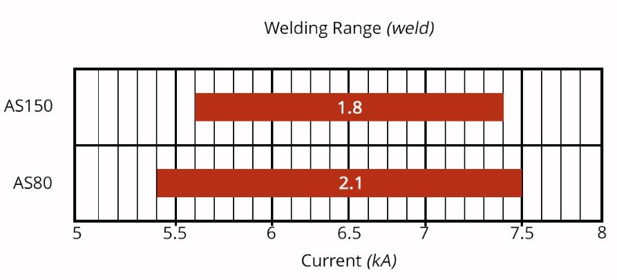
Cross sectioned spot welds made on press hardened steel with different coating weights of an Aluminum -Silicon coating is presented in Figure 6. Note the displaced coating at the periphery of weld. Figure 7 shows the difference in current range required to produce acceptable welds associated with these different coating weights. The thicker coating shows a smaller current range. In addition, the press-hardened Al-Si coating has a much higher melting point than the zinc coatings typically found on cold stamped steels, making it more difficult to displace from the weld area.
Figure 7: Influence of Aluminum-Silicon coating weight on welding range.O-16
Liquid Metal Embrittlement and Resistance Spot Welding
Cold-formable, coated, Advanced High Strength Steels are widely used in automotive applications. One welding issue these materials encounter is increased hardness in the weld area, that may result in brittle fracture of the weld. Another issue is their sensitivity to Liquid Metal Embrittlement (LME) cracking.
The most effective solution for these issues is using current pulsation during the welding cycle, schematically described in Figure 8.
Figure 8: Nugget growth differences in Single Pulse vs. Multi-Pulse Welding
Pulsation of the current allows much better control of the heat generation and weld nugget development. Pulsation variables include the number of pulses (typically 2 to 4), current, time for each pulse, and the cool time between the pulses.
Pulsation during Resistance Spot Welding is beneficial for press hardening steels, coated cold stamped steels of all grades, and multi-material stack-ups. Information about multi-sheet, multi-material stack-ups can be – as described in our articles on 3T/4T and 5T Stack-Ups
Equipment, Responsibilities, and Property Development Considerations When Deciding How A Part Gets Formed
Automakers contemplating whether a part is cold stamped or hot formed must consider numerous ramifications impacting multiple departments. Over a series of blogs, we’ll cover some of the considerations that must enter the discussion.
The discussions relative to cold stamping are applicable to any forming operation occurring at room temperature such as roll forming, hydroforming, or conventional stamping. Similarly, hot stamping refers to any set of operations using Press Hardening Steels (or Press Quenched Steels), including those that are roll formed or fluid-formed.
Equipment
There is a well-established infrastructure for cold stamping. New grades benefit from servo presses, especially for those grades where press force and press energy must be considered. Larger press beds may be necessary to accommodate larger parts. As long as these factors are considered, the existing infrastructure is likely sufficient.
Progressive-die presses have tonnage ratings commonly in the range of 630 to 1250 tons at relatively high stroke rates. Transfer presses, typically ranging from 800 to 2500 tons, operate at relatively lower stroke rates. Power requirements can vary between 75 kW (630 tons) to 350 kW (2500 tons). Recent transfer press installations of approximately 3000 tons capacity allow for processing of an expanded range of higher strength steels.
Hot stamping requires a high-tonnage servo-driven press (approximately 1000 ton force capacity) with a 3 meter by 2 meter bolster, fed by either a roller-hearth furnace more than 30 m long or a multi-chamber furnace. Press hardened steels need to be heated to 900 °C for full austenitization in order to achieve a uniform consistent phase, and this contributes to energy requirements often exceeding 2 MW.
Integrating multiple functions into fewer parts leads to part consolidation. Accommodating large laser-welded parts such as combined front and rear door rings expands the need for even wider furnaces, higher-tonnage presses, and larger bolster dimensions.
Blanking of coils used in the PHS process occurs before the hardening step, so forces are low. Post-hardening trimming usually requires laser cutting, or possibly mechanical cutting if some processing was done to soften the areas of interest.
That contrasts with the blanking and trimming of high strength cold-forming grades. Except for the highest strength cold forming grades, both blanking and trimming tonnage requirements are sufficiently low that conventional mechanical cutting is used on the vast majority of parts. Cut edge quality and uniformity greatly impact the edge stretchability that may lead to unexpected fracture.
Responsibilities
Most cold stamped parts going into a given body-in-white are formed by a tier supplier. In contrast, some automakers create the vast majority of their hot stamped parts in-house, while others rely on their tier suppliers to provide hot stamped components. The number of qualified suppliers capable of producing hot stamped parts is markedly smaller than the number of cold stamping part suppliers.
Hot stamping is more complex than just adding heat to a cold stamping process. Suppliers of cold stamped parts are responsible for forming a dimensionally accurate part, assuming the steel supplier provides sheet metal with the required tensile properties achieved with a targeted microstructure.
Suppliers of hot stamped parts are also responsible for producing a dimensionally accurate part, but have additional responsibility for developing the microstructureand tensile properties of that part from a general steel chemistry typically described as 22MnB5.
Property Development
Independent of which company creates the hot formed part, appropriate quality assurance practices must be in place. With cold stamped parts, steel is produced to meet the minimum requirements for that grade, so routine property testing of the formed part is usually not performed. This is in contrast to hot stamped parts, where the local quench rate has a direct effect on tensile properties after forming. If any portion of the part is not quenched faster than the critical cooling rate, the targeted mechanical properties will not be met and part performance can be compromised. Many companies have a standard practice of testing multiple areas on samples pulled every run. It’s critical that these tested areas are representative of the entire part. For example, on the top of a hat-section profile where there is good contact between the punch and cavity, heat extraction is likely uniform and consistent. However, on the vertical sidewalls, getting sufficient contact between the sheet metal and the tooling is more challenging. As a result, the reduced heat extraction may limit the strengthening effect due to an insufficient quench rate.
Thanks are given to Eren Billur, Ph.D., Billur MetalForm for his contributions to the Equipment section, as well as many of the webpages relating to Press Hardening Steels at www.AHSSinsights.org.
The initial press hardening steels of the 1970s were delivered bare, without a galvanized or aluminized layer for corrosion protection (i.e., uncoated). During the heating process, an oxide layer of FeOx forms if the furnace atmosphere is not controlled. Through the years, several coating technologies have been developed to solve the following problems of uncoated steels:F-14, F-33
Scale formation, which causes abrasive wear and requires a secondary shotblasting process before welding,
Decarburization, which leads to softening close to the surface,
Risk of corrosion.
The first commercially available coating on press hardening steels was patented in 1998. The coating was designed to solve the scaling problem, but it also offered some corrosion resistance.C-24 Since the coating composition is primarily aluminium, with approximately 9% silicon, it is usually referred to as AlSi, Al-Si, or AS.
Coating thickness is nominally 25 μm (75 g/m2) on each side and referenced as AS150. A more recent offering is a thinner coating of approximately 13 μm, and is referenced as AS80.A-51 The AS coating requires a special heating curve and soaking time for better weldability, corrosion resistance and running health of the furnace. Most OEMs now include furnace dew point limitations to reduce/avoid hydrogen embrittlement risk.
In 2005, Volkswagen was looking for a method to manufacture deep drawn transmission tunnels and other complex-to-form underbody components using press hardened steels. Although AS coatings were available, parts could not be formed to the full draw depth using the direct process, and the coating on the AS coated blanks cracked during the cold forming portion of the two-step hybrid process. Using uncoated blanks led to severe scale formation, which increased the friction coefficient in hot forming. For this particular problem, a varnish coating was developed. The coating was applied at a steel mill, and shipped to Volkswagen’s stamping plant. The varnish coated blanks were first cold pre-formed and then heated in a furnace, as seen in Figure 1a. Hot pre-forms were then deep drawn to full depth tunnels. As shown in Figure 1b, scale formed on parts which did not have the coating. A varnish coated blank could be cold formed first without crack formation in the coating, and then hot formed without any scale, Figure 1c.S-63, F-34 Since then, some other varnish coatings also have been developed.
Figure 1: Transmission tunnel of 6th generation Volkswagen Passat (2005-2014): (a) hot forming of pre-form, and final parts: (a) uncoated blank would suffer from scaling, (c) scale-free parts can be formed from varnish-coated blanks.F-34
In car bodies, components that are sealed from external moisture are referred to as dry areas. These areas have low risk of corrosion. Areas that may be exposed to moisture are wet areas. Precautions must be taken to avoid corrosion of the sheet metal, such as using galvanized or pre-coated steel. Sealants can also be applied to joints to keep out moisture. The presence of humidity in these areas increases the risk of forming a galvanic cell, leading to accelerated corrosion. These areas have higher risk of corrosion and may require additional measures. Figure 2 shows dry and wet areas. In this figure, parts colored with yellow may be classified as wet or dry, depending on the vehicle design and the OEMs requirements.G-41
Figure 2: Dry and wet areas in a car body. (re-created after G-41)
An estimated ~40% of press hardened components are in dry areas. Thus, high corrosion protection is desired in the 60% of all press hardened components which are employed in wet areas.B-48 Zn-based coatings are favored for their cathodic protection, but require tight process control. The first commercial use of Zn-coated PHS was in 2008, using the indirect process.P-20 Since then, direct forming of Zn-coated PHS has been studied. When direct formed, furnace soaking temperature and time must be controlled carefully to avoid deep microcracks.G-41, K-20 Recently developed are two new Zn-coated press hardening steel grades, 20MnB8 and 22MnSiB9-5, both reaching approximately 1500 MPa tensile strength after processing. Using these grades requires a pre-cooling process after the furnace to solidify the Zn-based coating. 20MnB8 can be direct hot formed after pre-cooling, whereas 22MnSiB9-5 can be formed in a transfer press in the “multi-step” process.K-21, H-27
Depending on the coating type and thickness, the process type, controls and investment requirements may change significantly. For example, some press hardening lines may be designed to form blanks with only Al-based coatings. Table 1 summarizes the advantages and disadvantages of several coating systems.
Table 1: Summary of Coatings Available for PHS.
Coating Type
Advantages
Disadvantages
Uncoated
Lower cost
No corrosion protection
Scale forms during press hardening (shotblasting)
Surface decarburization (reduces strength)
Al-Based
No scale formation
No decarburization
Barrier corrosion protection from surface Al2O3 oxide layer
Weldable without sand blasting (oxide layer is thin enough)
No cathodic protection
Limited to direct process
High maintenance cost in roller hearth furnaces (coating sticks to rollers)
Only for direct process (cracks form if cold stamped)
Hard surface and abrasive
Zn-Based
Cathodic protection
May have lower friction coefficient
No decarburization; no scale
Cathodic corrosion protection
May require indirect or pre-cooled process
Risk of microcracks
Surface oxide slows but does not stop Zn evaporation
Liquid Zn can lead to LME and adhesion of Zn to tools
Sand blasting may be needed to remove oxide layer for welding
Varnish
Fast heating possible
Risk of microcracks
Direct, Indirect, Two-Step Hybrid, Roll-form PHS can be achieved
Applied at stamping facility
May require sandblasting for weldability
Uncoated Blanks
The earliest press hardening steels did not have any coating on them. These steels are still available and may be preferred for dry areas in automotive applications. If the steel is uncoated and the furnace atmosphere is not controlled, scale formation is unavoidable. Scale is the term for iron oxides which form due to high temperature oxidation. Scale thickness increases as the time in furnace gets longer, as seen in Figure 3. Scale has to be removed before welding, requiring a shotblasting stage. Thicker scale is more difficult and more costly to remove.M-53 Early attempts to reduce (if not avoid) scale formation saw the use of an inert-gas atmosphere inside the furnace.A-52 Today, a mixture of nitrogen (N2) and natural gas (CH4) is typically used.F-35 In China, at least one tier supplier is using a vacuum furnace to prevent scale formation.A-68
Figure 3: Oxide layer (scale) on press hardened steel after: (a) fast resistance heating (10 seconds in air), (b) furnace heating (120 seconds in air).M-53
While heating uncoated steel in the furnace, if the conditions are favorable for iron (Fe) oxidation, carbon (C) may also be oxidized. When the carbon is oxidized, layers close to the surface lose their carbon content as gaseous carbon monoxide (CO) and/or carbon dioxide (CO2) is produced.S-87 The depth of the “decarburization layer” increases with dwell time in the furnace, until an oxide layer (scale) formed. Scale acts as a barrier between the bare steel and atmosphere. As the carbon is depleted in the “decarburization layer”, the hardness of the layer is decreased, as seen in Figure 4. Decarburization is usually undesirable since it lowers the strength/hardness and may negatively affect fatigue life.C-26
Figure 4: Hardness distribution of an uncoated steel after 6 minutes in a 900 °C furnace, showing hardness decrease as the surface layers lose their carbon. (Re-created after C-26.
Several methods are available to improve the corrosion resistance of uncoated PHS parts:
E-coating after welding, before painting is a typical step of car body manufacturing, for rustproofing.
If descaling can be done by using chromium shots (in shotblasting), a thin film of chromium-iron may grow on the surface and improve the corrosion resistance.F-14
Vapor galvanizing (also known as Sherardizing) of uncoated steel after descaling, an experimental study described in Citation G-42.
Electro-galvanizing after hot stamping, as described in Citation A-68.
Change the base metal chemistry to one that is more oxidation resistant.L-60 Figure 5 compares the shiny non-oxidized surface appearance of parts made from this grade with that made from a conventional uncoated press hardening grade on the same production line with the same processing conditions.W-28
Figure 5: Oxidation resistant PHS grades may not need descaling or coatings for sufficient corrosion resistance. (re-created after W-28).
Aluminium-Based Coatings
The first commercially available coating on press hardening steels was patented by Sollac (now part of ArcelorMittal) in 1998. This coating was designed to address the scaling problem, but also offers some barrier corrosion resistance.C-24 The nominal coating composition is 9-10 wt.% Si, 2-4 wt.% Fe, with the balance Al.L-39 The coating may be referred to as AlSi, Al-Si, AluSi or more commonly AS. Nominal as-delivered coating thickness is 25 μm (approximately 75 g/m2) on each side, and is usually referred to as AS150, with 150 referencing the total coating weight combining both sides, expressed as g/m2. More recently, a thinner coating of 13 μm (30-40 g/m2 on each side, AS60 or AS80) is now commercially available.A-51 When AS coated blanks are “tailor rolled,” the coating thickness is also reduced in a similar percentage of the base metal thickness reduction. Corrosion protection is similarly reduced, and furnace parameters need to be adjusted accordingly.
As delivered, AS150 has a coating thickness of 20-33 μm and a hardness of approximately 60 HV. The “interdiffusion layer” (abbreviated as IDL) has a high hardness and low toughness at delivery, as seen in Figure 6a. Due to the brittle nature of the IDL, AS coated blanks cannot be cold formed unless very special precautions are taken. During heating, iron from the base metal diffuses to the coating forming very hard AlSiFe (or AlFe) layers close to surface. At the same time, Al and Si of the coating diffuse to the IDL, growing it in thickness and reducing its hardness, Figure 6b. Earlier studies have shown that heating time (and also furnace temperature) has direct effect on the final thickness of IDL, as shown in Figure 7. Once the IDL thickness surpasses approximately 16 to 17 μm, the welding current range (ΔI = Iexpulsion – Imin) may be well below 2 kA.V-15, V-21, W-34 The dwell time must be long enough to ensure proper surface roughness (see Figure 6b) for e-coatability.M-27, T-40Figure 10 summarizes the heating process window of AS coatings. The process window may change with base metal and coating thicknesses.
Figure 6: AS coating micrographs: (a) as-delivered, (b) after hot stamping process (re-created after V-15, V-21, W-34, G-32)
Figure 7: IDL thickness variation with furnace dwell time (Image created by B-55 using raw data from V-21, G-32, K-41.)
Hydrogen induced cracking (HIC, also known as hydrogen embrittlement) has been a major problem for steels over 1500 MPa tensile strength. AS coated steels may have higher diffusible hydrogen, when delivered, due to the aluminizing process occurring at 680 °C. In addition, AS coated grades may have a hydrogen absorption rate up to three times higher during heating.C-27 To reduce the hydrogen diffusion, it is essential to control the heating process (both heating rate and dew point in the furnace). AS coated blanks absorb hydrogen at room temperature; however, this happens at much lower rates than uncoated or Zn-coated blanks.J-21 Diffusible hydrogen can be removed from the press hardened part by re-heating the part to around 200 °C for 20 minutes or longer, in a process called de-embrittlement.V-21, G-32, G-43,J-21
For the abovementioned reasons, AS coated higher strength grades (i.e., PHS1800 and over) are required to have precise “dew point regulations” during the heating in furnace. Their final properties, especially elongation and bending angle, may be guaranteed only after paint baking, as shown in Figure 8.B-32 Paint baking is standardized in Europe as a treatment for 20 minutes at 170 °C, which may act like a de-embrittlement treatment.E-10Some OEMs also require dew point control and “subsequent de-embrittlement treatment” for AS coated PHS1500. This is typically done by the tier supplier, before the paint baking process.
Figure 8: Effect of diffusible hydrogen (Hdiff) on mechanical properties of: (a) uncoated PHS2000, (b) AS coated PHS2000 in an uncontrolled furnace atmosphere (re-created using raw data from C-27).
Another method to reduce the risk of hydrogen embrittlement is to adjust the coating composition. The bath chemistry for a standard AS coating consists of up to 90% aluminium, about 8% to 11% silicon and a maximum of 4% iron. Adding a maximum of 0.5% alkaline earth metals, like magnesium, for example has been shown to result in 40% less hydrogen diffusion into steel.R-29,T-45
Although not common in the industry, Al-Zn and Zn-Al-Mg based coatings have also been developed for press hardening processes.F-14 Recently introduced is an aluminium-silicon coating with magnesium additions. When oxidized with water vapor, Mg releases less H2 and thus may reduce the diffusible hydrogen.S-88
AS coatings may cause costly maintenance issues in roller hearth furnaces, as the coating may contaminate the rollers.B-14 Special care has to be taken to avoid the issue or prolong the maintenance intervals.
Zinc-Based Coatings
AS coatings provide some corrosion protection, known as “barrier protection”, as the coating forms a barrier between the oxidizing environment and the bare steel. It is quite common in Europe for a car to have 12 years corrosion protection warranty. To achieve such corrosion resistance, a typical car may have over 85% of its components galvanized.S-89
The use of Zn-coated PHS has been relatively low, compared to AS coated and uncoated grades. In 2015, 76% of the PHS sold in EU27+Turkey was AS coated. In these markets, 18% of the PHS sold was uncoated and only 6% was Zn coated.D-20 This can be attributed to the susceptibility of Zn-coated PHS to Liquid Metal Embrittlement (LME, also known as Liquid Metal Assisted Cracks (LMAC) and Liquid Metal Induced Embrittlement (LMIE)).C-28, L-46
After heating and soaking in the furnace, the base metal should be in the austenitic phase. During heating, the Zn coating reacts with the base metal and forms a thin solid layer of body-centered-cubic solid solution of Zn in α-Fe, shown as α-Fe(Zn) in Figure 9. During deformation, a microcrack can be initiated in this layer at the grain boundaries of the austenite in the base metal, as indicated in Figure 9a. As the crack propagates, zinc from the α-Fe(Zn) layer diffuses along the austenite grain boundary and combines with iron from the base steel to form additional α-Fe(Zn), Figure 9b. Cracks propagate through the weak a-Fe(Zn) grain boundary layer, allowing liquid zinc (with diffused iron) to advance into the capillary crack (Figure 9c). After quenching, the base metal transforms to martensite and the liquid Zn transforms to a hard and brittle intermetallic phase, Γ-Fe3Zn10.C-28
Figure 9: Schematic illustration of microcrack formation. (re-created based on C-28.)
In the direct forming of Zn-coated blanks, with or without pre-cooling, microcracks in the base metal may be observed. Microcracks less than 10 μm into the base metal does not affect the fatigue strength of the part.K-20 Microcrack depth is a function of coating thickness, furnace conditions (temperature and dwell time, see Figure 10), forming severity and forming temperature. It may be possible to direct form galvannealed (GA coated, ZF or ZnFe in the coating) blanks.
The boiling point of pure zinc (907 °C) is very close to the austenitization temperature of 22MnB5 (885 °C), so the heating process window of Zn-coated blanks must be controlled precisely. When the furnace dwell time is too short, deeper microcracks may be observed. When the furnace dwell time is too long, corrosion performance may be degraded. Thus, heating process window of Zn-coated blanks is significantly narrower than that of AS-coated blanks, as seen in Figure 10.B-14, S-90
Figure 10: Heating process window of AS and Zn coatings (representative data, may not be accurate for all sheet and coating thicknesses, re-created based on B-14, S-90.
Zn-based coatings may result in very low diffusible hydrogen after press hardening. In one studyJ-21, no diffusible hydrogen was detected, as long as the furnace dwell times are shorter than 6 minutes. Even after 50 minutes in the furnace, diffusible hydrogen was found to be around 0.060 ppm. Zn coatings do not act as a barrier for hydrogen desorption (losing H through the surface). Even at room temperature, Zn coated blanks may lose most of the diffusible hydrogen within a few days (also referred to as aging). See Figure 11.
Figure 11: Evolution of galvanized coating: (a) as delivered: Ferrite+Pearlite in base metal, almost pure Zn coating with Al-rich inhibition layer, (b) at high temperatures: austenite in base metal + α-Fe(Zn) and liquid Zn + surface oxides, (c) after press hardening: martensite in base metal + α-Fe(Zn) and Γ-phase coatings + surface oxides. The oxides are removed prior to welding and painting.J-21
Zn-based coatings may have a yellowish color after hot stamping. The surface oxides have to be removed before welding. This is typically done by shotblasting.
PHS blanks with a ZnNi coating were previously available. The ZnNi coating provided a low friction coefficient, a large process window in the furnace, the ability to be cold formed (indirect or two-step hybrid processes were also possible) and decreased susceptibility to LME.B-56 ZnNi coated PHS was used in the rear rail of the Opel Adam city carH-57 for a short period, until the coating was discontinued.C-29
Varnish Coatings
Another method to avoid scaling and decarburization is to apply varnish coatings, Figure 12. In this method, uncoated steel can be either coil coated or blanks can be manually coated with the paint-like varnish coatings.B-14 These coatings may also be referred to as “paint-type” or “sol-gel”.
Figure 12: Manual application of a varnish coating.F-34
Depending on the type of coating, they may allow very fast heating – including induction and conduction heating with electric current. Since the coating does not require time to diffuse, furnace heating may be completed in less than 2 minutes.F-34 Again, depending on the type, surface conditioning may not be required before welding or e-coating.B-14
They were used in automotive industry between 2005 and 2010. By 2015 there were four different types of varnish coatings, some of which are now discontinued.B-14 These coatings may be useful for prototyping and low volume production.
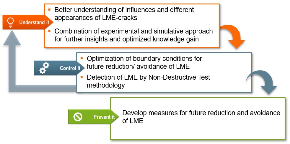
WorldAutoSteel releases today the results of a three-year study on Liquid Metal Embrittlement (LME), a type of cracking that is reported to occur in the welding of Advanced High-Strength Steels (AHSS).The study results add important knowledge and data to understanding the mechanisms behind LME and thereby finding methods to control and establish parameters for preventing its occurrence. As well, the study investigated possible consequences of residual LME on part performance, as well as non-destructive methods for detecting and characterizing LME cracking, both in the laboratory and on the manufacturing line (Figure 1).
Figure 1: LME Study Scope
The study encompassed three different research fields, with an expert institute engaged for each:
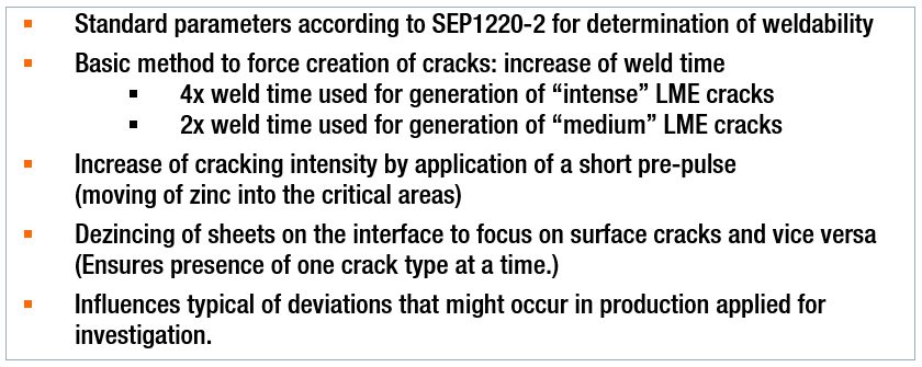
A portfolio containing 13 anonymized AHSS grades, including dual phase (DP), martensitic (MS) and retained austenite (RA) with an ultimate tensile strength (UTS) of 800 MPa and higher, was used to set up a testing matrix, which enabled the replication of the most relevant and critical material thickness combinations (MTC). All considered MTCs show a sufficient weldability under use of standard parameters according to SEP1220-2. Additional MTCs included the joining of various strengths and thicknesses of mild steels to select AHSS in the portfolio. Figure 2 provides the welding parameters used throughout the study.
Figure 2: Study Welding Parameters
In parallel, a 3D electro-thermomechanical simulation model was set up to study LME. The model is based on temperature-dependent material data for dual phase AHSS as well as electrical and thermal contact resistance measurements and calculates local heating due to current flow as well as mechanical stresses and strains. It proved particularly useful in providing additional means to mathematically study the dynamics observed in the experimental tests. This model development was documented in two previous AHSS Insights blogs (see AHSS Insights Related Articles below).
Understanding LME
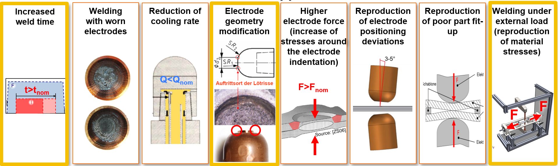
The study began by analyzing different influence factors (Figure 3) which resembled typical process deviations that might occur during car body production. The impact of the influences was analyzed by the degree of cracking observed for each factor. A select number of welding set-ups from these investigations were rebuilt digitally in the simulation model to replicate the process and study its dynamics mathematically. This further enabled the clarification of important cause-effect relationships.
Figure 3: Overview of All Applied Influence Factors (those outlined in yellow resulted in most frequent cracking.)
Generally, the most frequent cracking was observed for sharp electrode geometries, increased weld times and application of external loads during welding. All three factors were closely analyzed by combining the experimental approach with the numerical approach using the simulation model.
Destructive Testing – LME Effects on Mechanical Joint Strength
A destructive testing program also was conducted for an evaluation of LME impact on mechanical joint strength and load bearing capacity in multiple conditions, including quasi-static loading, cyclic loading, crash tests and corrosion. In summary of all load cases, it can be concluded that LME cracks, which might be caused by typical process deviations (e.g. bad part fit up, worn electrodes) have a low intensity impact and do not affect the mechanical strength of the spot weld. And as previously mentioned, the study analyses showed that a complete avoidance of LME during resistance spot welding is possible by the application of measures for reducing the critical conditions from local strains and exposure to liquid zinc.
Controlling LME
In welding under external load experiments, the locations of the experimental crack occurrence showed close correlation with the strains and remaining plastic deformations computed by the simulation model. It was observed that the cracks form at the location of the highest plastic strains, and material-specific threshold values for critical strains were derived. The threshold values then were used to judge the crack formation at elongated weld times.
At the same time, the simulation model pointed out a significant difference in liquid zinc diffusion during elongated weld times. Therefore, it is concluded that liquid zinc exposure time is a second highly relevant factor for LME formation.
The results for the remaining influence factors depended on the investigated MTCs and were generally less significant. In more susceptible MTCs (AHSS welded with thick Mild steel), no significant cracking occurred when welded using standard process parameters. Light cracking was observed for most of the investigated influences, such as low electrode cooling rate, worn electrode caps, electrode positioning deviations or for gap afflicted spot welds. More intense cracking (higher penetration depth cracking) was only observed when welding under extremely high external loads (0.8 Re) or, even more, as a consequence of highly increased weld times.
For the non-susceptible MTCs, even extreme situations and weld set-ups (such as the described elongated weld times) did not result in significant LME cracks within the investigated AHSS grades.
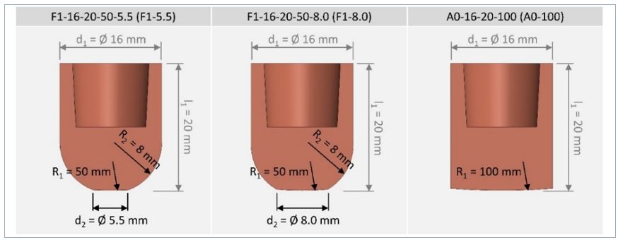
Methods for avoidance of LME also were investigated. Changing the electrode tip geometry to larger working plane diameters and elongating the hold time proved to eliminate LME cracks. In the experiments, a change of electrode tip geometry from a 5.5 mm to an 8.0 mm (Figure 4) enabled LME-free welds even when doubling the weld times above 600 ms. Using a flat-headed cap (with small edge radii or beveled), even the most extreme welding schedules (weld times greater than 1000 ms) did not produce cracks. The in-depth analysis revealed that larger electrode tip geometries clearly reduce the local plastic deformation around the indentation. This plastic strain reduction is particularly important, as longer weld times contribute to a higher liquid zinc exposure interval, leading to a higher potential for LME cracks.
Figure 4: Electrode Geometries Used in Study Experiments
It was also seen that as more energy flows into a spot weld, it becomes more critical to parameterize an appropriate hold time. Depending on the scenario, the selection of the correct hold time alone can make the difference between cracked and crack-free welds. Insufficient hold times allow liquid zinc to remain on the steel surface and increased thermal stresses that form after the lift-off of the electrode caps. Elongated hold times reduce surface temperatures, minimizing surface stresses and thus LME potential.
Non-Destructive Testing: Laboratory and Production Capabilities
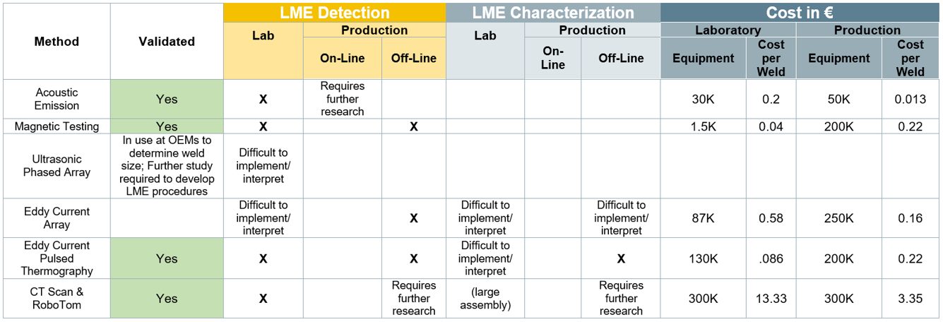
A third element of the study, and an aid in the control of LME, is the detection and characterization of LME cracks in resistance spot welds, either in laboratory or in production conditions. This work was done by the Institute of Soudure in close cooperation with LWF, IPK and WorldAutoSteel members’ and other manufacturing facilities. Ten different non-destructive techniques and systems were investigated. These techniques can be complementary, with various levels of costs, with some solutions more technically mature than others. Several techniques proved to be successful in crack detection. In order to aid the production source, techniques must not only detect but also characterize cracks to determine intensity and the effect on joint strength. Further work is required to achieve production-level characterization.
The study report provides detailed technical information concerning the experimental findings and performances of each technique/system and the possible application cost of each. Table 1 shows a summary of results:
Table 1: Summary of NDT: LME Detection and Characterization Methods
Preventing LME
Suitable measures should always be adapted to the specific use case. Generally, the most effective measures for LME prevention or mitigation are:
Avoidance of excessive heat input (e.g. excess welding time, current).
Avoidance of sharp edges on spot welding electrodes; instead use electrodes with larger working plane diameter, while not increasing nugget-size.
Employing extended hold times to allow for sufficient heat dissipation and lower surface temperatures.
Avoidance of improper welding equipment (e.g. misalignments of the welding gun, highly worn electrodes, insufficient electrode cooling)
In conclusion, a key finding of this study is that LME cracks only occurred in the study experiments when there were deviations from proper welding parameters and set-up. Ensuring these preventive measures are diligently adhered to will greatly reduce or eliminate LME from the manufacturing line. For an in-depth review of the study and its findings, you can download a copy of the full report at worldautosteel.org.
LME Study Authors
The LME study authors were supported by a committed team of WorldAutoSteel member companies’ Joining experts, who provided valuable guidance and feedback.
Related Articles: More on this study in previous AHSS Insights blogs: