This article explores the challenges of liquid metal embrittlement (LME) in resistance spot welding (RSW) of automotive components, particularly focusing on a component-scale S-Rail made from advanced high-strength steel (AHSS). The study aims to identify the occurrence of LME during the welding process and to propose effective strategies for its mitigation. This article is an excerpt from the “LME component study” conducted by WorldAutoSteel. The full study can be downloaded here.
Experimental and Simulative Setup
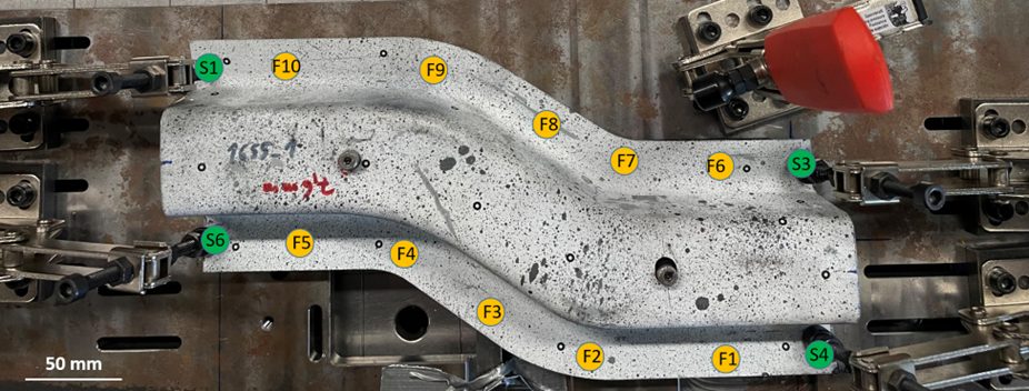
The experiments utilized an electrogalvanized RA1180 AHSS joined to hot-dip galvanized mild steel. Two stack-up configurations were tested: similar (both sheets made of RA1180) and dissimilar (RA1180 on top of mild steel). The resistance spot welding process was monitored using sensors to record current, voltage, and force. Different welding parameters, such as hold time and electrode geometry, were varied to observe their effects on LME.
Figure 1: Top-view of the S-Rail component during welding. The clamping points S1-S4 as well as the welding points F1-F10 are highlighted.
A simulation-based risk criterion for LME was established based on local stresses in the components. Both experimental and numerical analyses were conducted to assess the influence of various parameters on LME formation. Specifically, the study evaluated how springback, a phenomenon occurring during deep drawing, affects LME risk. Correct clamping can effectively suppress springback, consequently reducing LME occurrences.
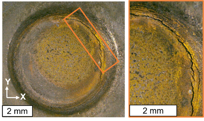
Figure 2: Experimentally observed cracks with 5° tilted electrodes and doubled welding time of 760 ms.
Findings
Influence of Springback: Springback contributed to LME formation. When clamping was employed to counteract springback, LME was effectively eliminated from the welded samples.
Electrode Geometry and Hold Time: Adjustments to the electrode geometry and increasing hold time after welding further mitigated LME risks. Specifically, larger electrode tip diameters and longer hold times reduced the likelihood of cracks.
Material Stack-up Effects: The experiments indicated that the configuration of the material stack-up influenced LME occurrences. Only stack-ups with thick joining partners showed occurrence of LME in the trials.
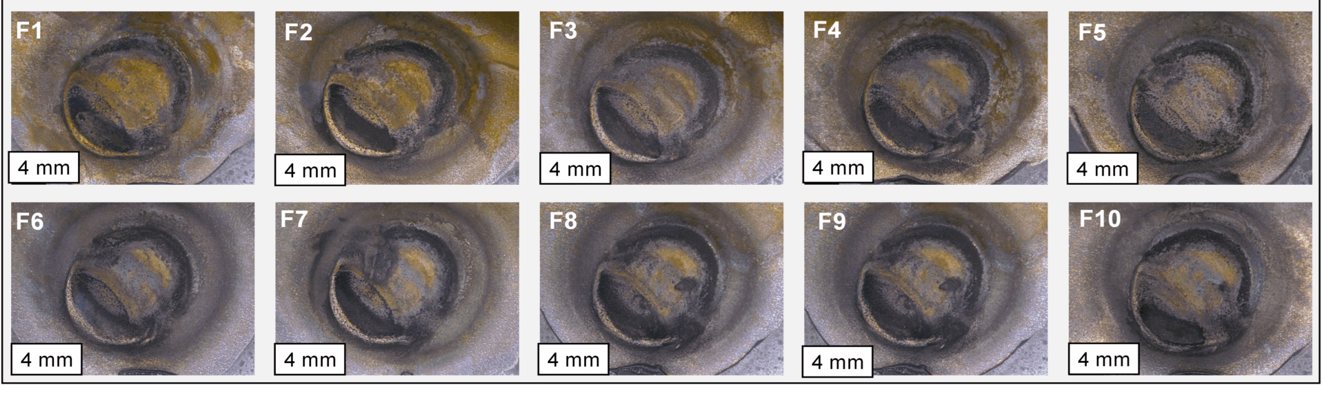
Figure 3: All 10 resistance spot welds on the S-rail are crack-free after optimizing either springback, electrode working plane diameter or post-weld hold time
Simulation Results
Finite element simulations were used to evaluate the risk of LME by analyzing local stresses and temperature distributions during welding. The results showed that the springback-affected samples presented a higher LME risk compared to idealized, straightened models. This finding aligns with experimental observations that cracks occurred where excessive springback influenced the welding process. Even in the case of springback, LME could be effectively prevented by using electrode caps with larger working planes as well as slightly extending the hold time after welding.
The developed simulation approach allows comparing the LME conditions for different welding setups and can therefore optimize the LME occurrence for geometry, material and welding conditions.
Conclusion
Effective mitigation strategies, such as clamping to suppress springback and adjustments in welding parameters, can prevent LME on a component-scale. It can also be highlighted that today’s AHSS grades are far less sensitive to LME by-default so that few RSW joints in a whole body-in-white are at all susceptible for cracking: To produce cracks for this study, welding parameters with increased energy input had to be used; no LME was observed under “standard” industrial conditions.
This article investigates the MIG brazing capability of coated steel sheets for automotive applications, focusing on MIG brazing as a viable alternative to MAG welding, especially for chassis components. The study aims to evaluate the impact of coatings on brazing ability, wettability, and arc stability. MIG brazing is increasingly being used for joining Body-in-White parts, especially when Resistance Spot Welding is unsuitable. This research investigates the potential of brazing coated steels, noting that MAG welding often leads to defects such as blowholes.
MIG Brazing Process
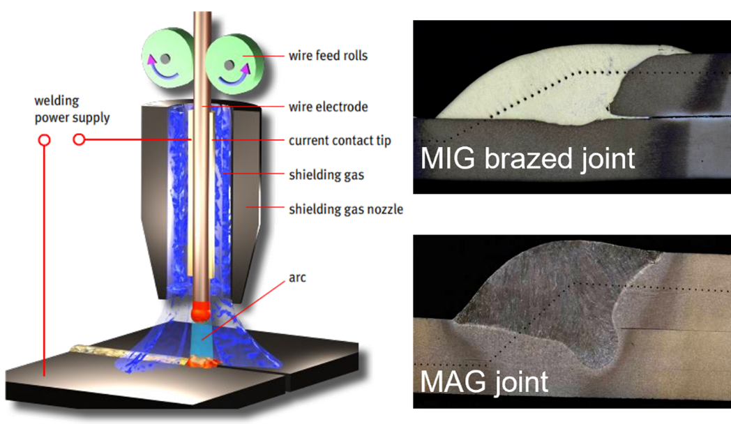
MIG brazing is similar to MAG welding but utilizes a low melting point filler wire, typically copper alloys, that does not melt the substrates. It primarily employs pure argon as shielding gas and a short-circuit transfer mode. The main advantages of MIG brazing over MAG welding include:
Lower heat input due to the lower melting temperature.
Reduced distortion, making it suitable for thin sheets used in automotive applications.
Improved visual appearance and less coating degradation, leading to better corrosion resistance.
Figure 1: MIG Brazing process with representative cross sections from brazing and welding
Methodology
The study focuses on overlap joints without gaps, using CuAl8 and CuSi3 filler wires with a diameter of 1.0 mm, and employs a short-circuit waveform at a welding speed of 500 mm/min. The results are expressed in terms of brazing range, focusing on criteria such as wettability of different coatings and spatter formation.
Key Findings
Wetting Studies: Two methods were used to study wettability—real MIG brazed samples and a wetting pilot. The results indicated that higher wire feed speeds lead to increased current and voltage, which enhances heat input and improves wettability despite a rise in molten metal volume.
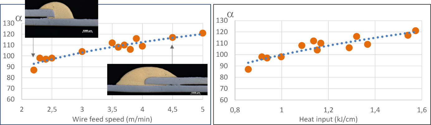
Figure 2: Effect of wire feeding speed and heat input on wetting angle using 0.8 mm thick sheets and CuAl8 filler wire
Influence of Coatings: The coatings had no significant effect on the wettability or arc stability. The behavior of Zinc-coated steels were like that of bare steel, with AlSi coating showing a wider brazing range due to its thicker and more refractory nature.
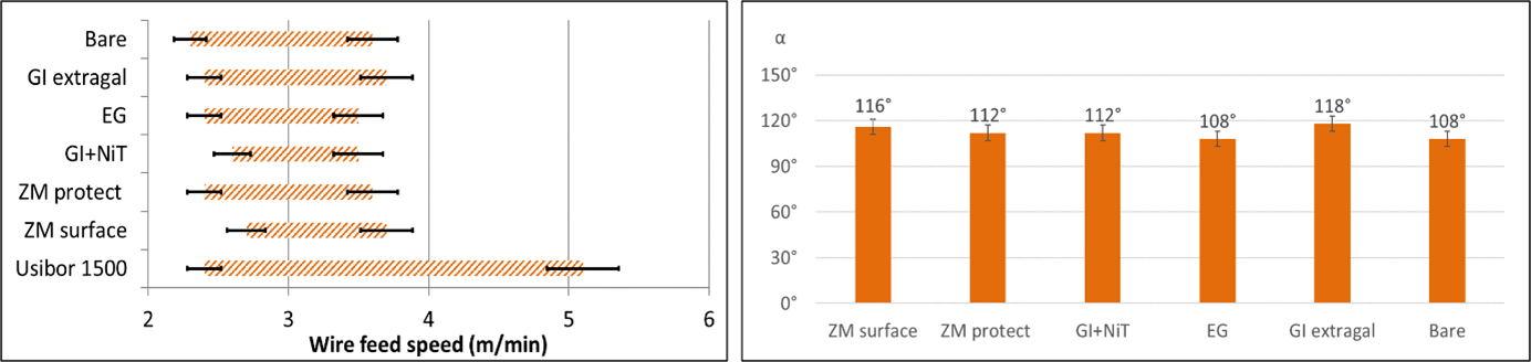
Figure 3: Brazing range and wetting angle for different coatings using 0.8 mm thick sheets and CuAl8 filler wire
Spatter Formation: Spatters measuring between 0.1 to 0.3 mm occurred, with a notable increase in spatter rates observed when using zinc coatings. This effect was consistent across various coatings.
Conclusion
The study concludes that the coating does not influence the MIG brazing capability, as the brazing range, wettability, and arc stability remained consistent. The AlSi coating exhibited a broader brazing range. Switching between coatings does not require a change in brazing parameters, although an increase in spatter is expected when brazing coated sheets in comparison to bare steels. In summary, MIG brazing is validated as an effective method for joining coated steel sheets in automotive applications, providing advantages in heat input and corrosion resistance over traditional arc welding. Source J. Haouas, MIG brazing ability of coated steel sheets for automotive applications, IIW 2020 conference, SC XVII
A dynamic tensile test was conducted to evaluate the mechanical properties of spot welds under automotive collision conditions. The actual tensile shear strengths of steel sheets with nominal tensile strengths ranging from 270 MPa to 780 MPa were investigated.
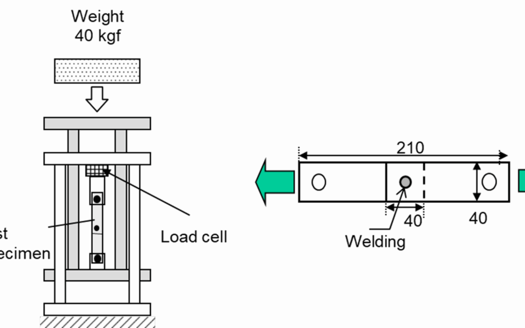
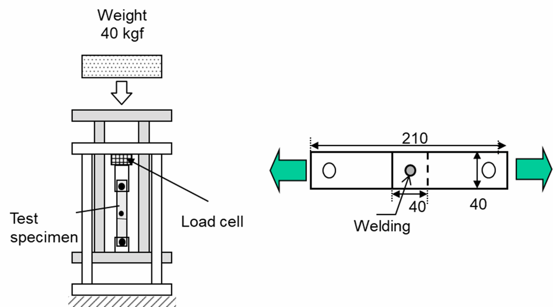
Figure 1 presents the dynamic tensile test machine and illustrates a schematic diagram of the tensile shear test specimen. A 1.6 mm thick steel sheet was placed on top of the tensile shear test specimen and spot welded, with nugget diameters of 5.5√t (7.0 mm) used for both. In the dynamic tensile test, a cone was dropped at high speed onto the specimen to apply a tensile load and determine the breaking point. The tensile speed was adjusted by varying the drop height of the cone, with a maximum speed of 2.4 m/s. For comparison, a static tensile test was conducted at a tensile speed of 1.6 × 10⁻⁴ m/s.
Figure 1: Dynamic tensile shear test equipment (left) and test specimen (right)
Results
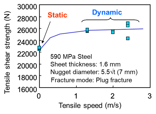
Figure 2 shows the relationship between tensile shear strength and tensile speed for the steel sheet with a rated tensile strength of 590 MPa. Tensile shear strength tended to increase with tensile speed, with values of approximately 22 kN and 25.5 kN under static and dynamic loading conditions, respectively. All specimens exhibited plug fracture as the failure mode
Figure 2: Relationship between tensile shear strength and tensile speed (steel sheet with a rated tensile strength of 590 MPa)
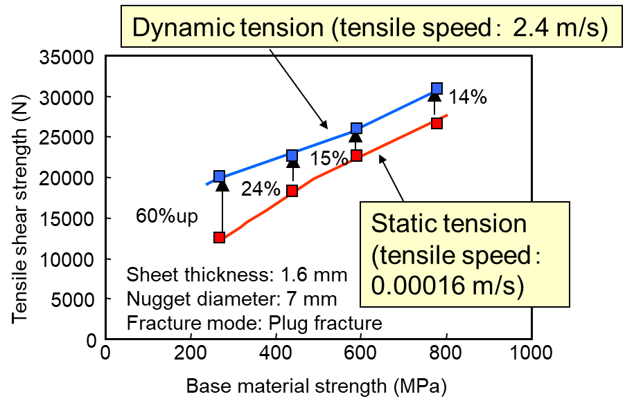
Figure 3 illustrates the effect of the tensile strength of the base material on the rate of increase in dynamic strength relative to static strength. Plug fracture remained the consistent failure mode across all cases. For the steel sheet with a rated tensile strength of 270 MPa, dynamic strength increased by approximately 60% compared to static strength. In contrast, the sheet with a rated tensile strength of 780 MPa showed an increase of only about 14%. These results indicate a tendency for the rate of increase in dynamic strength relative to static strength to decrease as the rated tensile strength of the steel increases. This is consistent with the general trend of mild steel strength increasing with strain rate, while strain rate sensitivity diminishes for higher-strength steels.
Figure 3: Relationship between dynamic and static tensile shear strengths of spot welds and base material strength
Source
Dynamic Tensile Shear Strength of Spot-Welded Joints: Experimental Investigation and Results Hiroki Fujimoto, Welding & Joining Research Laboratories, Nippon Steel Corporation
Automotive engineers have substantially more steel grades to select from in their quest to balance properties, performance, manufacturability, sustainability, and cost.
Conventional dual phase steels, with a microstructure of simply ferrite and martensite, have excellent formability in the drawing and stretching deformation modes. However, the characteristics of this phase combination that work very well in these deformation modes lead to challenges in bending and edge-stretch deformation.
Complex phase steels have superior performance in bending and edge-stretch deformation, but are not as good as comparable-strength dual phase steel.
3rd Generation Advanced High Strength Steels are a family of grades that can combine the best features of other steels while minimizing some of their associated constraints.
Below are examples of how steel grades were applied to various parts in order to solve specific challenges.
B-Pillar (Center Pillar)
B-Pillars are a particularly challenging part for cold stamping applications. The upper section must be of sufficiently high strength to prevent cabin intrusion during a side impact, while the lower section needs to maintain at least moderate ductility to absorb crash energy. Stiffness improves with deeper draw depth and more shape, yet the necessary formability to achieve these are typically limited by the high strength requirements. Furthermore, the door opening regions require flanges to facilitate joining of outer and inner components. Production manufacturing constraints dictate that the blank edges are usually formed by mechanical shearing rather than laser cutting, and forming the targeted part shape puts these cut edges in tension – exposing the risk for edge cracks of these higher strength steels. The combination of these challenges contributed to many OEMs choosing to form B-Pillars and entire door rings using hot stamping of press hardening steels.
Development of new types of advanced high strength steels bring the cold stamping option back into focus.
B-Pillar Upper
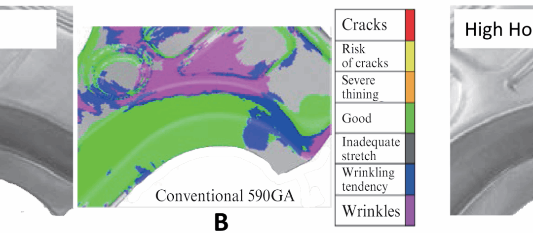
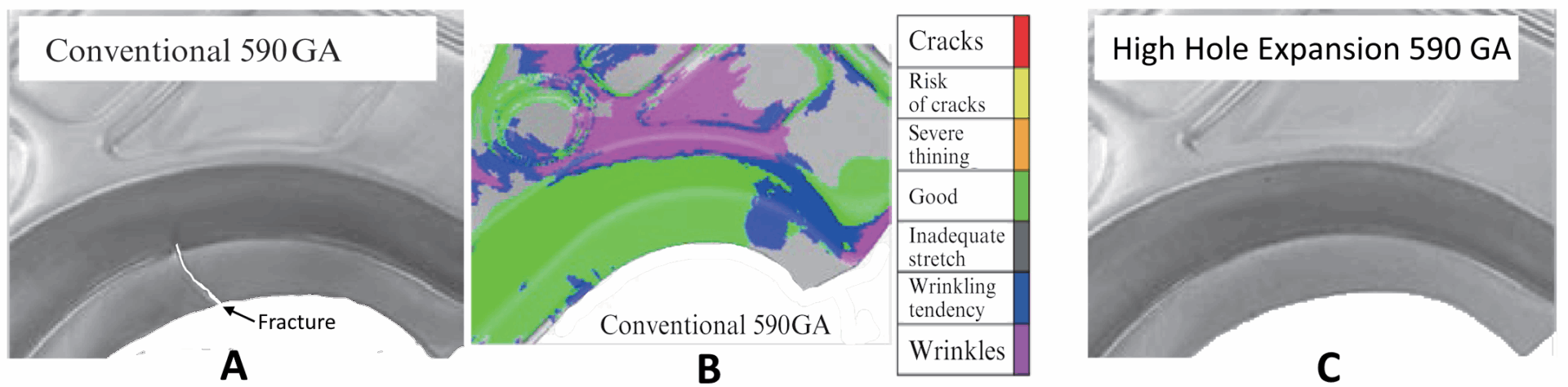
Metal flow when forming shear-cut blanks into B-Pillar Upper shapes puts the cut edges into tension along the front- and rear- door opening regions adjacent to the B-Pillar. Edge cracking propagating into the part, such as seen in Figure 1a, is frequently the outcome. Making this more challenging is that simulations have difficult predicting risk of cut edges, exemplified by Figure 1b which gives the false impression that there are no cracking or splitting concerns in this area.
Blank design countermeasures accomplish only so much. However, the steel industry now offers options at the same tensile strength but having better cut edge ductility as measured by the hold expansion test. The same part and process design is now capable of achieving the targeted part dimensions and characteristics, Figure 1c.
Figure 1: B-Pillar Upper stamped from conventional 590 GA (1a) and 590 GA with high hole expansion (1c). Figure 1b shows the simulation of the conventional 590 GA but does not indicate forming issues.S-125, J-30
Table 1 presents a comparison of the properties used to form these parts.
Table 1: Typical Properties of Conventional 590 GA and High Hole Expansion 590 GA.J-30
Steel
Type
Yield Strength
(MPa)
Tensile Strength
(MPa)
Elongation
(%)
HER* λ
(%)
Conventional 590 GA
365
610
29
45
High Hole Expansion 590 GA
410
600
33
80
*HER: Hole Expanding Ratio, the index of stretch-flangeability.
B-Pillar Lower
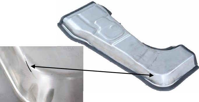
OEMs usually design B-Pillar Lower portions to absorb side impact crash energy. This means a combination of lower gauge and lower strength. Vehicle stiffness must be maintained, so the lower horizontal portion may have a relatively deep draw depth – also needed to accommodate the contours of the rocker shape. From a formability perspective, the deep draws and aggressive designs put these stampings (Figure 2a) at risk of splits due to insufficient elongation and n-value. An example of a split section is shown in Figure 2b. However, no issues were found when stamped from a 3rd Generation 980 MPa steel, Figure 2c.
Figure 2: B-Pillar Lower (a) showing splits when made from conventional 980 GA (b), and split-free when made from 3rd Gen 980 MPa (c).J-30
A-Pillar (Front Pillar)
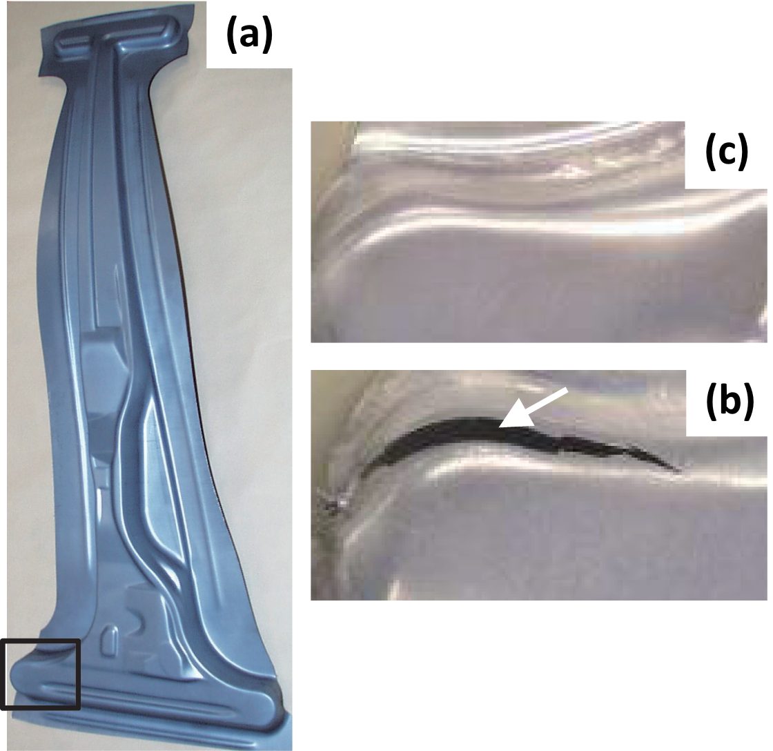
A-Pillar Lowers, also called front pillar lowers, have similar formability concerns as the B-Pillar Lower, except that A-Pillars are usually formed from even higher strength grades since they are at the front corners of the passenger safety cage. The typical design leads to the fractures seen in Figure 3, arising from insufficient elongation and n-value in the steel. Application of a 3rd Generation 1180 MPa steel overcame these concerns, leading to robust and successful stamping.
Figure 3: Deep draw depths make A-Pillar Lower panels at risk for splitting. Converting to a 3rd Gen 1180 MPa steel may alleviate these concerns.S-125, J-31
Application of Dual Phase Steels to Exposed-Quality Surface Panels
Bake hardening steels frequently are used for exposed panels due to the extra strengthening occurring from the paint curing step. Of the bake hardenable grades, 340 BH is likely the most widely applied. In this terminology typically used in some parts of Asia, these grades have a minimum tensile strength of 340 MPa, and a minimum yield strength of approximately 200 MPa. As such, a 340 BH grade is similar to a 210 BH grade, using terminology more often associated with North America- and Europe based companies.
The option of a higher strength bake hardenable steel exists with a 440 DP product: a dual phase steel that has a minimum tensile strength of 440 MPa and has bake hardenability. The as-produced yield strength of 340 BH and 440 BH are similar, but the 440 BH grade has a larger strength increase associated with the paint curing step.F-51 The low yield strength of 440 BH is attributed to having martensite in the ferrite matrix. With a now higher strength panel, a thickness reduction of 0.05 mm is possible while still improving dent resistance.J-29
Table 2 compares these steels, with YP’ representing the in-panel and baked strength, which is the sum of the yield point (YP), work hardening (WH), and bake hardening (BH).
Table 2: Typical Properties of 340 BH and 440 DP Steels Applied to Exposed Panels.J-29
Steel
Type
Yield Strength
(MPa)
Tensile Strength
(MPa)
Elongation
(%)
n-value
(6% to 12%)
WH
(MPa)
BH
(MPa)
YP’
(MPa)
340 BH
242
354
41
0.21
33
35
310
440 DP
257
455
37
0.23
62
57
376</td
YP’ (formed and baked strength) = yield point (YP) + work hardening (WH) + and bake hardening (BH).
Align Alloy Selection to the Needs of the Part
Alloy Selection of 980 MPa Steel
Body structures often call for parts to be formed from 980 MPa tensile strength steel. Recognizing that strength is not the only characteristic that determines whether the part can be successfully and robustly stamped into the targeted shape and dimensions, the steel industry offers different Advanced High Strength Steel grades to meet the minimum tensile strength requirements.
Citations M-77 and M-78compare three such grades: DP980, CP980, and QP980, all cold rolled steel at 1.6 mm thick. The DP grade is a standard dual phase steel, CP represents a complex phase steel, and QP indicates that it is a Quenched and Partitioned 3rd Generation AHSS grade. Table 3 compares the tensile properties of the 3 steels, and Figure 4 shows the stress strain curves for these grades. The bold portions of the curves in Figure 4b comes from tensile testing which generates data through uniform elongation. From that point, the curves are extrapolated to the true fracture strain εf determined by analyzing the dimensions of the fractured tensile bars.
Table 3: Tensile properties of Three AHSS Grades with 980 MPa Minimum Tensile Strength.M-77,M-78
Steel
Type
Yield Strength
(MPa)
Tensile Strength
(MPa)
Uniform Elongation
(%)
Total Elongation
(%)
True Fracture
Strain (εf)
DP980
662
1,016
8.9
15.8
0.44
QP980
654
1,005
15.9
22.1
0.78
CP980
941
1,046
8.2
14.6
0.58
Properties representative of samples evaluated in Citations M-77 and M-78.
Figure 4: a) Engineering and b) True Stress-strain curves for DP980, QP980, and CP980.M-77
Strain hardening was characterized as a function of strain, Figure 5. The lack of a constant n-value prevents use of the Holloman relationship to characterize the hardening curves. Necking occurs once the true strain equals the work hardening coefficient (ε = n).
The initial peak in Dual Phase steel at low strains comes from the high work hardening offered by the microstructural ferrite, but decreases as the ferrite strengthens with increasing strain. The plateau in the strain hardening coefficients for the QP980 and CP980 steels is consistent with the occurrence of the TRIP effect. The microstructural differences between the three AHSS types are directly related to their performance in formability characterization tests like tensile and bending.
Figure 5: Strain hardening coefficient as a function of strain for DP980, QP980, and CP980.M-77
As indicated in Figure 6, the steels have different microstructures. Dual phase steels are comprised of ferrite (α) and martensite (α’); the QP steel has ferrite (α), martensite (α’), and ≈6% retained austenite (γ); and the microstructural components of the CP steel include ferrite (α), martensite (α’), bainite (αb), and ≈6% retained austenite (γ).
Figure 6: Microstructural components of DP980, QP980, and CP980.M-77
In V-Bending tests described in Citations M-77 and M-78, the greatest strains were found in bends made on the DP980 steel, while the QP980 steel resulted in the lowest strains at the bend radius. The high n-value at high strains seen in QP980 reduces strain concentration along the bending line, and therefore reduces the peak strain at this location. The springback angle was the largest in the CP980 steel, which is consistent with having the highest yield strength.
Alloy Selection of 1180 MPa Steel
Stamped parts experience multiple modes of forming deformation, including drawing, stretching, and bending. Some, but not all, advanced high strength steels having a multiphase microstructure are sensitive to cut-edge stretching as measured in a hole expansion test. The key to stamping success is to deploy the correct steel grade that addresses the challenges and constraints of the part. AHSS grades offer options to address these challenges.
As one example, conventional 980DP and 1180DP was compared to 3rd Gen 1180 in these various deformation modes.M-54
The tensile and hole expansion properties of these grades are listed in Table 4, while Figures 7 to 9 shows the bendability, stretch formability, and deep drawability of the three grades. The forming limit curve of the 3rd Gen 1180 steel is comparable to 980DP. Additional testing confirms each of these steels are spot weldable with conventional techniques and have excellent resistance to delayed fracture associated with hydrogen embrittlement.M-54
Table 4: Tensile and hole expansion properties of 3rd Gen 1180, 1180DP, and 980DP.M-54
Steel
Type
Yield Strength
(MPa)
Tensile Strength
(MPa)
Elongation
(%)
HER* λ
(%)
3rd Gen 1180
946
1,222
18
40
1180 DP
910
1,185
10
51
980 DP
640
1,020
17
25
*HER = Hole expansion tested to JIS Z 2256; 1.4mm; JIS Z 2201 #5 tensile sample in transverse orientation
Figure 7: Bendability of 3rd Gen 1180 steel compared with 1180DP and 980DP.M-54
Figure 8: Stretch formability of 3rd Gen 1180 steel compared with 1180DP and 980DP.M-54
Figure 9: Deep drawability of 3rd Gen 1180 steel compared with 1180DP and 980DP.M-54