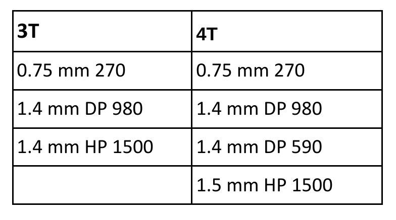
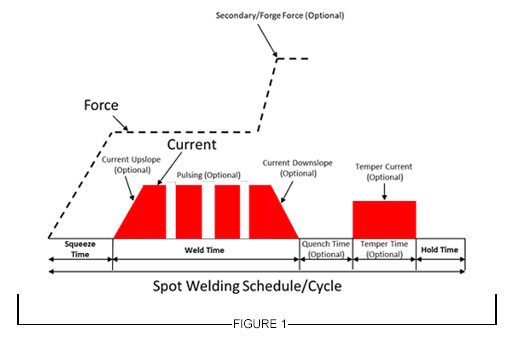
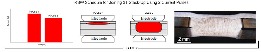
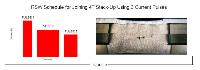
Every industry has its own jargon. In certain settings, these words might be necessary – you wouldn’t want a cardiologist talking to a gastroenterologist about boo-boos and upset tummies. But when these professionals talk with their patients, it’s sometimes necessary for them to use much simpler words. That is, assuming the goal is to actually communicate the issues and concerns.
The steel industry is no different. We use words that have precise meanings in our daily discussions, and we forget that many people we work with don’t have exposure to the terminology that we are accustomed to using. What follows is a brief tour of the words and phrases you are likely to hear when speaking with your metallurgical representative.
Let’s start with the most common word: steel. Simply, steel is just an alloy of iron with up to about 2% carbon. Of course, other elements are in the composition. These fall into two categories: those intentionally added to improve one or more properties (called alloying elements), and those remaining from the steelmaking process that are too costly to remove relative to the benefit the removal would provide (called residual elements). High residuals are usually bad, typically because they lower ductility. But remember high is a relative term. The value may be higher than the standard to which you ordered (which is a cause for rejection), or just higher than what you’ve received in the past. If they are within the tolerance allowed within the standard, the product should still meet your strength and ductility requirements.
I’ve worked with metal formers who believe “steel is steel” and that all grades should behave the same way. According to the World Steel Association, there are more than 3,500 different grades of steel, each with unique properties and characteristics, 75% of which were developed in the past 20 years. Certainly, not all of these are sheet steels, but even within this category, there are sizable numbers. When it comes to just advanced high-strength sheet steels, more than 60 unique grades are available today.
The most common sheet steel grade is routinely called mild steel. Mild steels are low-carbon steels with no alloying elements added for substantial strengthening, and for that reason, they are characterized by relatively lower yield strength. However, there is no single grade or chemistry that meets this definition. Grade definitions require the steelmaker to meet certain chemistry or property limits. These grades are ordered to a standard usually written by the steel producer, a pertinent industry society (like ASTM, Euronorm, or JFS), or the end-user OEM. What is generally thought of as mild steel has chemistry, strength, and ductility overlapping many defined grades. Steel users should order to standards that define and constrain important properties like strength and ductility.
If you hang out with enough metallurgists, you are bound to hear passionate discussions about the iron-carbon phase diagram. (Why you are hanging around metallurgists is another topic entirely.) Before explaining the purpose of a phase diagram, it’s important to understand that a phase is a region of a material that is physically distinct, chemically uniform, and can be seen as different from the rest of the material. Ice and water are two phases that exist in my beverage. You’ll find a chocolate chip phase in my vanilla ice cream. And you’ll find ferrite in my steel – tasty! The properties of each of these change if you increase temperature (converting H2O from a solid to a liquid and eventually a gas) or if you add more alloying elements (chocolate chips or carbon). If you add a lot of that alloying element, you can get something entirely different like ripple or pearlite.
A phase diagram is a graphical representation of composition on the horizontal axis and temperature on the vertical axis. Two important phase diagrams are shown below. The far-left side of each represents 100% vanilla or 100% iron. Different phases exist as the temperature increases, or as the product is alloyed with increasing amounts of either chocolate or carbon.

Figure 1: Vanilla-Chocolate Phase Diagram A-77

Figure 2: Iron Carbon Phase DiagramA-78
Atoms arrange themselves in three-dimensional patterns called lattices. Think about billiard balls in multiple layers. The balls can be one layer directly above the prior one, or they can be shifted and rest in the crevice formed by adjacent balls in the layer below. The balls are all the same material, but the gap size changes with different arrangements. This is what happens with steel. At lower temperatures, only up to 0.02% carbon fits in the gap. This orientation is called ferrite. At higher temperatures, a different atomic orientation is stable, which we call austenite. Up to 2% carbon can fit into this arrangement of atoms. For low-carbon steels under normal conditions, austenite cannot exist at room temperature – when the steel is slowly cooled, it changes from austenite to a combination of ferrite and a mixture of phases called pearlite. However, heating a certain chemistry to the austenitic zone followed by rapidly cooling just right bypasses the natural conversion to ferrite and pearlite, and creates a structure that contains austenite at room temperature. This leads to the term retained austenite, which is the phase that gives TRIP and 3rd Generation Steels excellent ductility. More on these later.
100% iron is very soft. As a matter of fact, 100% of any element is very soft. As an example, think about gold. 24-carat gold is pure gold. You might think that a wedding ring, as a symbol of long-lasting love and devotion, should be made from 100% gold. In reality, many gold bands are made from 12-carat gold, which is half gold and half impurities. (Showing your love by giving something 50% impure perhaps is not the best marketing approach.) Adding alloying elements to gold is done to improve certain characteristics, like strength, making the alloy appropriate for the applications it serves.
When we talk about ferrite at room temperature, that’s iron with no more than 80 parts per million carbon. That’s really close to pure iron, so when we hear the term ferrite, we should think of something that is really soft, low-strength, and very ductile.
If additional strength is needed, then more alloying elements must be used in addition to carbon. The next most cost-effective alloying element is manganese which produces higher-strength steels called carbon-manganese steels. These are substitutional solid solutions strengthened, where the atoms of manganese swap into where atoms of iron would otherwise go. These grades have limited ductility, especially at higher carbon and manganese contents, so they are used in structural applications that do not need a lot of formability and are therefore also called structural steels (SS). In the ASTM standard specification covering many sheet steels, ASTM A1008/A1008M, these grades are grouped in the SS category.
Around 1980, steelmakers rolled out a new approach to getting higher strength levels while minimizing the loss of elongation usually seen with higher strengths. They do this by strengthening the ferrite through the addition of very small quantities of titanium, niobium, and vanadium to form carbide and nitride precipitates. These microalloying additions are used in precipitation hardening of the ferrite to create High Strength Low Alloy (HSLA) steels.
Switching gears a bit to discuss something unrelated to sheet steel but a process with which we might be familiar: forged gears. We want forged gears to be hard and high strength. Typical production of gears involves heating up a steel alloy of certain chemistry, followed by rapid cooling (quenching) them faster than a critical cooling rate. The structure that’s produced is called martensite. If the quench rate is only a little too slow, a different phase called bainite can be produced. While martensite is the highest strength phase, it has limited elongation. Bainite is a little lower in strength but has higher elongation and toughness compared with martensite. Bainite shines in applications needing cut-edge ductility during stretch flanging.
Martensite wasn’t commonly found as a microstructural component during most of the history of automotive sheet steels due to the limited number of companies having an annealing line with appropriate quenching capabilities. This started to change around the turn of the millennium when newer annealing lines were installed with the ability to hold at a specific temperature which may be lower than the annealing temperature followed by quenching to another much lower temperature. This led to greater production of the first generation of Advanced High-Strength Steels (AHSS), including grades that have a microstructure of only martensite.
Dual Phase steels are the most common AHSS. As you might guess, there are two phases in Dual-Phase steels. Ferrite and martensite are the two phases: ferrite is super-soft and comprises the majority of the microstructure, while martensite is super-hard and takes up 10% (590DP) to 40% (980DP) of the microstructure. The more martensite, the stronger the steel. Elongation is the ductility measured in a tensile test, and since most of the structure is ferrite, these steels have exceptional elongation for the strength level. However, there is a large hardness difference between ferrite and martensite, leading to crack initiation sites and resulting in poor cut-edge ductility during stretch flanging.
[A brief digression on testing. Tensile testing takes a standard sample shape, typically looking like a bone you might give a dog to chew on, and pulls it in tension from the edges. The test results include yield strength, tensile strength, and total elongation, commonly called the YTEs or TYEs based on the initials. More information comes out of the tensile test, covered elsewhere. However, the tensile test is usually not used to measure cut-edge ductility. Cut edge ductility is typically characterized by the hole expansion test, where a punched hole is expanded with a conical punch until a through-thickness crack forms.]
Ferrite-bainite steels have a combination of decent elongation (from the ferrite) and excellent cut-edge ductility (from the bainite). Yes, your assumption is correct that there are only two phases in these steels, with ferrite being about 85% of the microstructure. Due to the way these are produced, ferrite-bainite steels are available as hot-rolled products only. That’s in contrast with Complex Phase (CP) steels, which can be found either at hot-rolled or cold-rolled thicknesses.
Soft ferrite is the primary microstructural component in DP steels and the soon-to-be-discussed TRIP steels, which results in low yield strength and relatively high elongation. On the other hand, the primary microstructural components of complex phase steels are bainite and precipitation-strengthened ferrite, with martensite and retained austenite also present in lower amounts. Lacking soft ferrite, these steels have relatively high yield strength and low elongation as measured in a tensile test, but the bainite leads to exceptional cut-edge ductility as measured in a hole expansion test. Multi-phase steels are a related product. Some OEMs group CP and MP steels in the same category, while others say that CP steels are engineered to favor improved bendability and cut edge extension over tensile elongation at the same tensile strength and that MP steels target balancing the fracture resistance needed for better bendability and hole expansion with the necking resistance found with higher uniform elongation and n-value.
TRIP steels contain mostly ferrite surrounding islands of martensite, as well as some bainite and retained austenite. The amount of bainite is pretty low, so it doesn’t add much to the cut-edge ductility. But the magic is in the retained austenite. Austenite is a very ductile phase. What makes this a special phase is that as austenite-containing steels deform, the atoms rearrange and the austenite transforms into martensite, giving the steel enhanced ductility. (Jargon alert: Another word for ductility used by professionals is plasticity.) A quick review: this enhanced ductility comes from austenite transforming to martensite. In other words, these steels have Transformation Induced Plasticity (TRIP).
Wouldn’t it be great to have an alloy that was just austenite? We’d have a high-strength, high-ductility product. There are two types of steels that are in this category. First are austenitic stainless steels in the 3XX family, like SS304 and SS316. In these alloys, austenite is stable at room temperature, but these require approximately 18% chromium and 8% nickel. Next are TWIP steels. These may look like TRIP steels from how they are written, but these steels get their plasticity differently. TWIP steels deform by a mechanism known as twinning, so they are described as Twinning Induced Plasticity Steels (TWIP). Of course, there are no free lunches. To get fantastic formability properties, a lot of alloying is necessary. This drives up the steelmaking complexity and cost. The alloying elements also make welding much more challenging. TWIP steels are called second-generation advanced high-strength steels.
The 3rd Generation Advanced High-Strength Steels (3rd Gen AHSS or 3rd Gen) are made possible by another advance in annealing technology, allowing steelmakers to produce a refined microstructure. Nearly all 3rd Gen steels have retained austenite in the microstructure and therefore benefit from a high strength, high ductility combination. The latest annealing lines used to make these steels come equipped to not just hold and quench to defined temperatures but have reheating capability followed by another hold and quench to different temperature targets. This allows for the creation of an engineered balance and distribution of ferrite, bainite, martensite, and austenite in the microstructure.
The resultant tensile property ranges from 3rd Gen steels produced at different companies may be similar, but their methods of getting those properties are a function of chemistry and the capabilities and characteristics of the equipment used to produce them. A different chemistry approach may result in different weldability, for example, so users are encouraged to perform thorough due diligence before switching suppliers. The days of steel being simply a commodity are in the past as it relates to these highly engineered higher strength steels.
Final thought 1: What’s an MPa?
This note may have a global readership, but this answer is focused on the countries that haven’t embraced the metric system. Megapascals, abbreviated MPa, is a measure of strength, just like pounds per square inch (psi) or force per area. Like Celsius and Fahrenheit or inches and millimeters, we can convert between them easily enough. There are 1000 psi in a ksi, with k being the abbreviation for kilopounds. And there are 6.895 ksi in an MPa. Make your life easier and focus on a 7:1 difference. 100 ksi is about 700 MPa.
Final thought 2: What about Press Hardening Steels?
Press hardening steel for hot stamping is a separate topic with a lot of nuances. One of the biggest differences is how the properties develop. For cold stamping operations, the stamping company is responsible for creating the formed part from sheet metal supplied to the necessary strength. With press hardening steels, the stamping company creates both the shape and the strength. Different grades come from a combination of different chemistries from the steelmaker and different heating and cooling profiles at the stamping location. The chosen corrosion protection approach impacts the various options. Learn more at the Press Hardening Primer on this site.
Final thought 3: Don’t hesitate to ask questions.
If your metallurgical representative says something that you don’t understand, ask for clarification. Your suppliers want to be your valued partner for more than just a simple transaction. Quite likely, your met rep is passionate about their offerings and would love to talk about them. If you get a deeper understanding of what makes one product different from another, then you’ll be in a better position to weigh the benefits against the inevitable constraints, leading to an optimized material selection. Remember, communication is the key to success for all parties.