homepage-featured-top, main-blog, News
There is interest in the sheet metal industry on how to adopt Industry 4.0 into their legacy forming practices to significantly improve productivity and product quality. Figure 1 illustrates four important variables influencing part quality: material properties, die friction response, elastic deflection of the tool, and press dynamic characteristics. These variables are usually difficult to measure or track during the production runs. When these variables significantly influence the part quality and the scrap rate increases, the operators manually adjust the forming press parameters (speed and pressure), lubricant amount, and tooling setup. However, these manual adjustments are not always possible or effective and can be costly for the increased part complexity.

Figure 1: Important variables influencing the stamping quality.H-35
The ultimate vision for Industry 4.0 in sheet metal forming is an autonomous forming process with maximum process efficiency and minimum scrap rate. This is very similar to the full self-driving (FSD) vision of the electric vehicle today. This will be valuable for the automotive industry that has to process large production volumes with various steel grades.
For example, normal variations of the incoming material properties for Advanced High-Strength Steel (AHSS) may have a significant effect on part quality associated with necking, wrinkling, and cracking, which in turn drastically increases the production cost. This variation of the incoming material properties increases uncertainty in sheet metal forming by making consistent quality more challenging to achieve, thereby increasing the overall manufacturing cost. A nondestructive evaluation (NDE) can be a useful tool to measure incoming material properties.
There are several types of NDE sensors. Most of the sensors need further development or are not suitable for production applications. However, some of the NDE sensors, such as the eddy current tools, laser triangulation sensors equipment, and equipment developed by Fraunhofer IZFP called 3MA (micromagnetic, multiparametric microstructure, and stress analysis), have already been applied to a few limited production applications. These sensors can be used to provide data during production to select the optimal parameters. They also can be used to obtain material properties for finite element model (FEM) analysis. Studies in deep drawing of a kitchen sink production used a laser triangulation sensor to measure the sheet thickness and an eddy-current sensor to measure the yield strength, tensile strength, uniform elongation, elongation to break, and grain size of the incoming material. The material data is used as an input for simulations to generate the metamodels to determine the process window, and it is used as an input for the feed-forward control during the process.K-27
Figure 2 shows how NDE tools are used for feed-forward controls and cameras for feedback control to determine the optimum press setting on sink forming production.

Figure 2: Process control for sheet metal forming of kitchen sink production.H-36
Another study proposed the use of Fraunhofer’s 3MA equipment to determine the mechanical properties of incoming blanks for a sheet forming process. The 3MA sensor correlates the magnetic properties of the material with the mechanical properties and calibrates the system with the procedure outlined in Figure 3. The study showed a good correlation between the measurements from the sensor and the tensile testing results; however, the sensor should be calibrated for each material. Also, the study proposed to use a machine-learning algorithm instead of a feed-forward control to predict the most effective parameters during the drawing process.K-28

Figure 3: Calibration procedure for 3MA sensors.K-28
Technologies associated with Industry 4.0 have a natural fit with AHSS. The advanced slide motion capabilities of servo presses combined with active binder force control can be paired with stamping tonnage and edge location measurements from every hit to create closed-loop feedback control. With press hardening steels (PHS), vision sensors and thermal cameras can be used for controlling the press machine and transfer system.
Have a look at the Dr. Kim’s detailed article on Industry 4.0 for more examples of NDE sensors, as well as information on applying Industry 4.0 to forming process controls.
Blog, homepage-featured-top, News
We thank Dennis McPike, Zapp Tooling Alloys, Inc. for contributing this insightful case study.
Multi-phase steels are complex to cut and form, requiring specific tooling materials. The tooling alloys which have been used for decades, such as D2, A2 or S7, are reaching their load limits and often result in unacceptable tool life. The mechanical properties of the sheet steels achieve tensile strengths of up to 1800 MPa with elongations of up to 40%. Additionally, the tooling alloys are stressed by the work hardening of the material during processing.
The challenge to process AHSS quickly and economically makes it necessary for suppliers to manufacture tooling with an optimal tool steel selection. The following case study illustrates the tooling challenges caused by AHSS and the importance of proper tool steel selection.
A manufacturer of control arms changed production material from a conventional steel to an Advanced High-Strength Steel (AHSS), HR440Y580T-FB, a Ferrite-Bainite grade with a minimum yield strength of 440 MPa and a minimum tensile strength of 580 MPa. However, the tool steels were not also changed to address the increased demands of AHSS, resulting in unacceptable tool life and down time.
According to the certified metal properties, the 4 mm thick FB 600 material introduced into production had a 525 MPa yield strength, 605 MPa tensile strength, and a 20% total elongation. These mechanical properties did not appear to be a significant challenge for the tool steels specified in the existing die standards. But the problems encountered in production revealed serious tool life problems.
To form the FB 600 the manufacturer used D2 steel. D2 was successful for decades in forming applications. This cold work tool steel is used in a wide variety of applications due to its simple heat treatment and its easily adjustable hardness values. In this case, D2 was used at a hardness of RC 58/60.
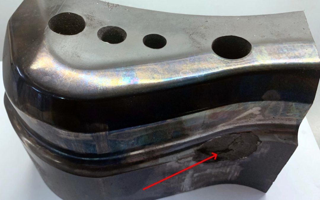
While tools manufactured from D2 can withstand up to 50,000 load cycles when forming conventional steels, these particular D2 tools failed after only 5,000 – 7,000 cycles during the forming of FB 600. The first problems were detected on a curl station where mechanical overload caused the D2 tools to break catastrophically, as seen in Figure 1 below. Since the breakage was sudden and unforeseeable, each failure of the tools resulted in long changeover times and thus machine downtime.

Figure 9: Breakage seen in control arm curl tool made from D2, leading to premature failure. Conversion to a PM tool steel having higher impact resistance led to 10x increase in tool life.M-20
Since the cause of failure was a mechanical breakage of the tools, a tougher alternative was consequently sought. These alternatives, which included A2 and DC53 were tested at RC 58-60 and unfortunately showed similar tool life and failures.
Metallurgical analysis indicated that the failure resulted from insufficient impact strength of the tool steel. This was caused by the increased cross-cut that the work-hardened AHSS exerted on the curl. As an alternative material, a cold work steel with a hardness of 58-60, a tensile strength of about 2200 – 2400 MPa and high toughness was sought. These properties could not be achieved with conventional tool steels. The toolmaker used a special particle metallurgy (PM) tool steel to obtain an optimum combination of impact strength, hardness and wear resistance.
Particle metallurgy (PM) tool steels, due to their unique manufacturing process, represent improvements in alloy composition beyond the capabilities of conventional tool steels. Materials with a high alloy content of carbide formers such as chromium, vanadium, molybdenum and tungsten are readily available. The PM melting process ensures that the carbides are especially fine in particle size and evenly distributed (reference Table 1). This process results in a far tougher tool steel compared to conventional melting practices.

Table 1: Elemental Composition of Chosen Tool Steel
The manufacturer selected Z-Tuff PM® to be used at a hardness of RC 58-60. Employing the identical hardness as the conventional cold work steel D2, a significant increase in impact strength (nearly 10X increase as measured by un-notched Charpy impact values) was realized due to the homogeneous microstructure and the more evenly distributed precipitates. This positive effect of the PM material led to a significant increase in tool life. By switching to the PM tool steel, the service life is again at the usual 40000 – 50000 load cycles. By using a steel with an optimal combination of properties, the manufacturer eliminated the tool breakage without introducing new problems such as deformation, galling, or premature wear.
AHSS creates tooling demands that challenge the mechanical properties of conventional tool steels. Existing die standards may not be sufficient to achieve consistent and reliable performance for forming, trimming and piercing AHSS. Proper tool steel grade selection is critical to ensuring consistent and reliable tooling performance in AHSS applications. Powder metallurgical tool steels offer a solution for the challenges of AHSS.
News
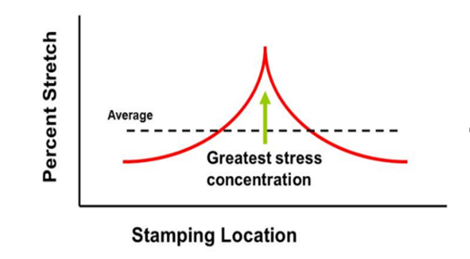
To understand the difference between localized and global fractures, you must first understand strain gradients (see the article in our blog, AHSS Strain Hardening and Gradients). Gradients can result in highly concentrated strains (peak strain condition) that typically occurs in an embossment or character line where the deformation mode is in plane strain. Peak strains can develop rapidly in a very localized area (Figure 1). Under additional loads, this can result in the onset of localized necking, which means the material has reached its tensile strength and will fail at its weakest point or highest strain. When a slight increase in strain is applied, the material will fracture, sometimes at deformation levels less than predicted. This condition can be found in AHSS products, where multiple phases exist within the steel’s microstructure, each with different properties. A global fracture also typically occurs in plane strain, but more commonly down a sidewall or other area with more moderate geometry complexity.
Figure 1: Peak strain in the localized area or embossment
Peak (concentrated) strains are susceptible to localized fractures when even slight variation exists in the forming process. Examples of variation include lubrication pattern and volume, die recipe including blank position, press conditions, and material characteristics.
A localized neck and/or fracture (Figure 2) reduces the sheet metal’s thickness, reducing part strength, and compromising functional performance such as fatigue life, crash worthiness, and stamping stiffness. There are a number of formability analysis tools that can differentiate localized and global fractures and enable die makers to implement die and process improvements that minimize fracture susceptibility. The result is a more robust stamping process.
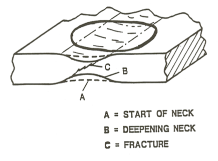
Figure 2: Schematic of Localized Necking and Fracture
Process control is critical; die recipe discipline is needed to minimize tinkering with die recipe, press settings, and lubrication settings. Mechanical properties of the sheet metal should be tracked to identify trends or variations in the material, and establish the material forming window. Typical mechanical properties that are available from the steel supplier are yield strength, tensile strength, n-value, total and uniformed elongation, and sheet thickness. Additional properties that should be determined include hole expansion and deep cup draw ratios. Failure to identify strain levels, process variables and variation will lead to a reactionary approach to controlling the output. This will lead to an increase in scrap, die-related downtime, and of course, costs.
Contributions made by Phoenix Group.

News
A common problem in every stamping plant is trim edge burrs. As new materials have been introduced, special trim breakage (clearance) or entry amounts may be required. Researchers are still trying to understand the edge stretching limits of these new materials. Edge stretching limits are directly linked to the reduction of the work hardening exponent (n-value) due to the cutting operation. As the material is cut during the coil slitting, blanking, trimming, or piercing operations, the tensile stretching on the sheared edge reduces the amount of formability remaining in the material. Finding the proper trim breakage and trim edge condition is critical. New test studies help steel producers understand the maximum stretch limits of the material they produce.
The Hole Expansion Test (HET) is the accepted form of measuring edge stretching limits. The test is performed by punching a hole in the center of a flat blank which is then clamped down, while a conical punch is pushed up through the hole, creating a stretch-flanged edge (see Figures 1 & 2). The output is the ratio of final hole diameter/initial hole diameter. The hole in the blank can be produced by various processes, to simulate manufacturing conditions. Some of the best results are produced by utilizing milled edges, laser cutting, EDM, and water jet.
In the world of stamping operations, reduced formability of a trim or pierced edge can equate to downtime, scrap, or rework. Since the use of EDM and Waterjets are not practical solutions, we evaluate current methods and materials that are available. The intention is to provide information to the people on the shop floor who might deal with this issue on any given day. Worn or chipped trim steels, improper clearances, and worn punches need to be repaired and maintained. New Advanced High-Strength Steels have lower forming limits compared to mild steel, and the introduction of a worn tool will reduce that forming range significantly. The use of powder metallurgy or cutting steels can help improve the number of hits between preventive maintenance intervals significantly. Some surface treatments can also extend tool life, achieving the same relative tool wear as conventional mild steels.
Figure 1: Schematic of a typical hole expansion test (HET)
conical punch/die setup.
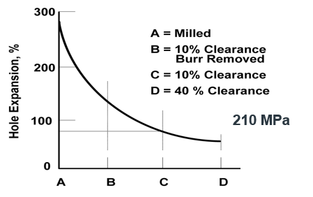
Figure 2: Schematic showing hole expansion capability for a 200 MPa mild steel for various punch conditions.
New grades such as Complex Phase (CP) steels have great strength, but also perform well in edge or stretch flange conditions because of bainite and grain refinement due to thermo-mechanical processing in the steel mill. Yet, the lack of proper tool maintenance can strip these steels of their performance advantage, as shown in Figure 3.
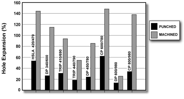
Figure 3: Hole expansion results for various AHSS grades, comparing effect of tool conditions.
Understanding the effects of tool wear rates, trim breakage, surface coating, and surface treatments will reduce downtime, scrap, and extend preventive maintenance intervals on trim and pierce dies. Providing training to the die makers on the newest materials, die components, and surface treatments available will help them make longer lasting corrections to stamping dies. Research and processes are evolving every day, resulting in new methods, products, and information for the successful stamping of Advanced High-Strength Steels.
Note: AHSS Application Guidelines Section 3.C.2 – Tool Materials and Die Wear contains more information that you may find helpful. Download the Guidelines free at www.worldautosteel.org.
Image References:
- Figure 1: (Schematic): H. Mohrbacher, “Advanced metallurgical concepts for DP steels with improved formability and damage resistance” – NiobelCon bvba
- Figure 2: R. Hilsen et al, “Stamping Potential of Hot-Rolled, Columbium-Bearing High-Strength Steels,” Proceedings of Microalloying 75 (1977).
- Figure 3: Courtesy of C. Walch, voestalpine Stahl GmbH.
Contributions made by Phoenix Group.
News
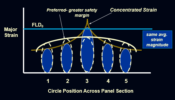
The mild steel currently being used for sheet metal stampings has higher n-values than High Strength Low Alloy Steel and Advanced High Strength Steel. The high n-value indicates that the material has a higher work hardening exponent making the steel much easier to stretch or form. The n-value describes how the material works together to resist localized fractures as stresses are applied. High strain patterns can be created in localized areas such as character lines and embossments. This strain pattern creates strain peaks or strain gradients. These strain peaks have much higher plastic deformation than areas on the rest of the material. The localized strain will cause the material to thin as it forms the character line or embossment. The die geometry does not allow the material to deform in stretch or draw modes, which means the material is in the plane strain mode of deformation on the Forming Limit Diagram (FLD). This deformation mode has the least amount of formability due to the location of the FLD₀anchoring point (See Figure 1).
Figure 1: Benefits of Uniformed Strain Distribution.
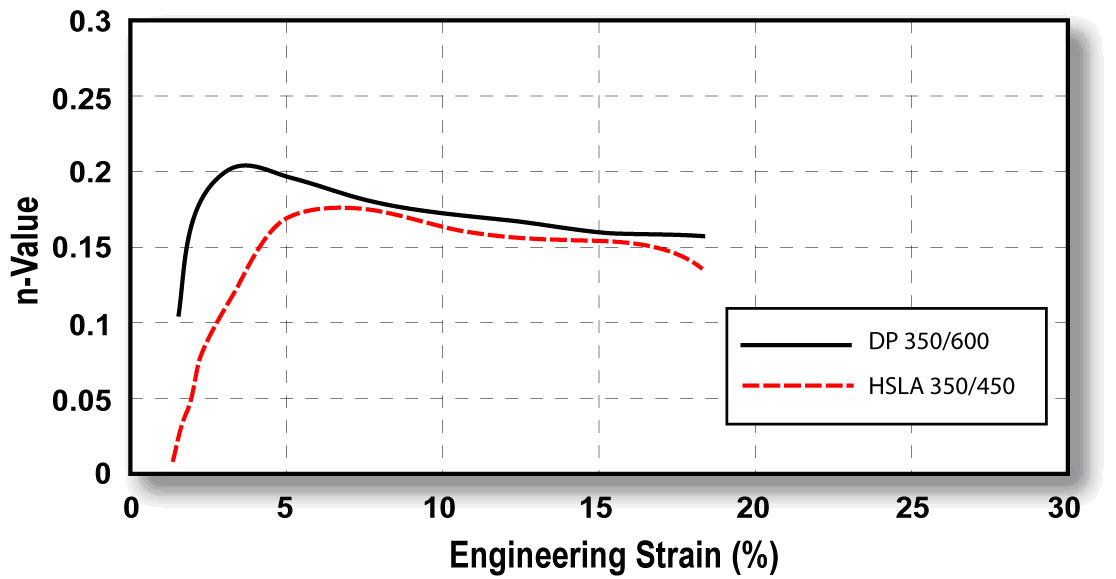
What does that mean for your stamping process? Mild steel has the ability to reach a high strain gradient due to higher n-values. High strength steels do not have the ability to reach the higher peak gradients due to lower n-values and less stretchability. These high strain areas will be more susceptible to a greater amount of thinning and/or fractures. If changes in the stamping process occur, such as reduced lube quantity, greater thinning can occur, at times exceeding minimum thickness and resulting in metal fracture. These concerns can be minimized through a better understanding of material capabilities, specific geometry effects, and the use of process recipe discipline. For example, Figure 2 compares the instantaneous n-value for Dual Phase steel, a member of the AHSS family, to HSLA steel. The early n-value increase reflects enhanced local formability, which is observed in stamped parts, contrary to what the typical stress-strain curve does not show the early n-value increase, which reflects enhanced formability in local regions of stamped parts. Other AHSS grades don’t show this tendency but have been developed with greater concentrations of bainite or finer dispersion of martensite within a ferrite matrix; both effects result in better localized forming.
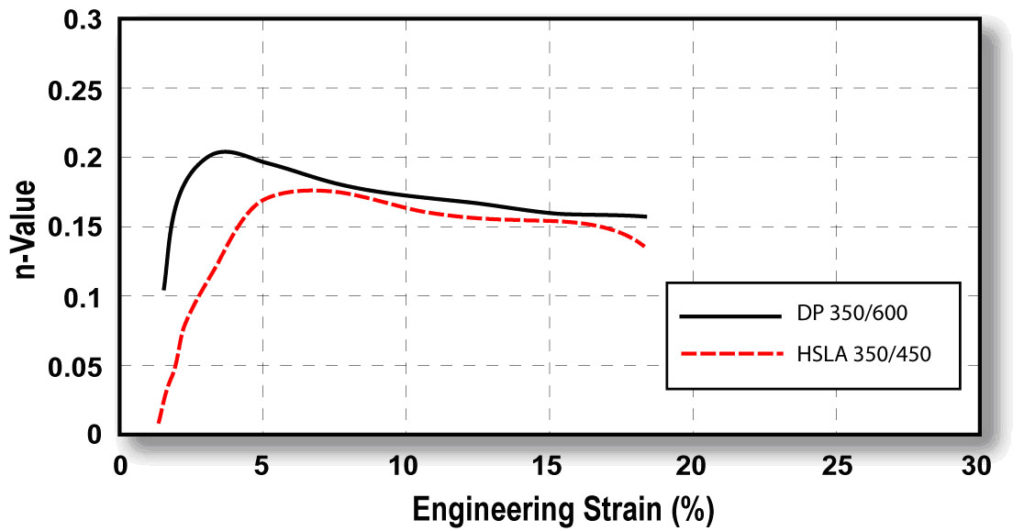
Figure 2: Instantaneous n-values versus strain for DP 350/600 and HSLA 350/450 steels.
Training die makers to understand these effects, while managing die geometry, will have a dramatic effect on the rework, downtime, and scrap associated with a conversion to AHSS products. The use of FLD₀ and formability analysis should identify areas of concern on the stamped part, but should also be coupled with hole expansion testing, or 2-D tension tests to more fully explore the formability condition. When trouble areas have been identified, there should be a review of the analysis and part with T&D managers, die makers, and quality personnel to formulate a corrective action plan. This plan should have specific and measurable direction, buy in, and understanding of the impact that die changes will have to the existing process.
BONUS!
Watch a video of renowned metallurgist Dr. Stuart Keeler explaining AHSS Instantaneous n-value:
Keeler On N-Value from worldautosteel on Vimeo.
Contributions made by Phoenix Group.
Figure 2 Image provided courtesy of Dr. Stuart Keeler.
News
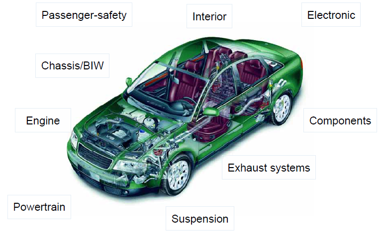
Figure 1: Laser Welding is commonly found in these vehicle subsystems.
Laser welding is finding its way into more vehicle applications due to inherent weld strength, adaptability to complex weld geometries, and lower part distortion (Figure 1). Automotive applications use a variety of welding joint designs for laser welding in both lap joint and seam butt joint configurations as shown in Figure 2. For example, laser butt-welding is used for welding tubes in roll-forming production lines as an alternative method for high frequency induction welding. Seam welds on butt joints need less power from the machine than lap joints due to the smaller weld fusion area, producing less distortion and a smaller heat affected zone (HAZ). Butt joint configurations are more cost efficient, however, the fit up for seam welds can be more difficult to obtain than those of lap joints.
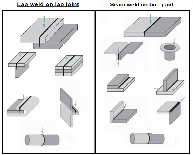
Figure 2: Common seam and joint types for laser welding of automotive applications.
When seam welding butt joint configurations, a general guideline for fit-up requirements include a gap of 3-10% the thickness of the thinnest sheet being welded, and an offset of 5-12% thickness of the thinnest sheet. Conversely, lap joints can require a gap of 5-10% the thickness of the top sheet being welded (Figure 3).
Laser welding is often used for AHSS lap (overlap) joints, but of course use different parameters compared to seam butt joint configurations. This type of weld is either a conventional weld with approximately 50% penetration in the bottom sheet or an edge weld. Welding is performed in the same way as for mild steels, but the clamping forces needed for a good joint fit-up are higher with AHSS than for mild steels. Lap joints tend to provide a larger process window, which can compensate for some of the manufacturing difficulties with AHSS, including springback and part distortion.
To achieve good laser-welded overlap joints for Zn-coated AHSS, a small intermittent gap (0.1-0.2 mm) between the sheets is recommended, which is identical to Zn-coated mild steels. In this way, the Zn does not get trapped in the melt, avoiding pores and other imperfections. An excessive gap can create an undesirable underfill on the topside of the weld.
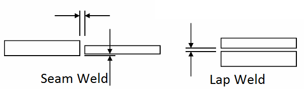
Figure 3: Fit-up requirements for butt joint and lap joint configurations in laser welding.
Studies have shown laser welding Zn-coated steels can be done without using a gap between the overlapped sheets. This is accomplished using dual laser beams. While the first beam is used to heat and evaporate the Zn coating, the second beam performs the welding. The dual laser beam configuration combines two laser-focusing heads using custom-designed fixtures.
AHSS grades can be laser butt-welded and are used in production of tailored products (tailor-welded blanks and tubes). The requirements for edge preparation of AHSS are similar to mild steels – in both cases, a good quality edge and a good fit-up are critical to achieve good quality welds.
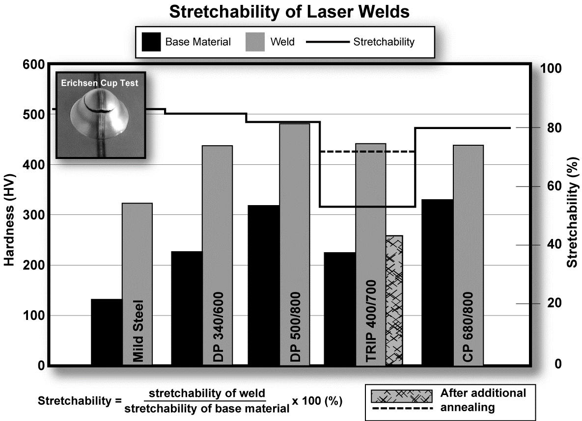
If a tailor-welded product is intended for use in a forming operation, a general stretchability test such as the Erichsen Olsen cup test can be used for assessment of the formability of the laser weld. AHSS with tensile strengths up to 800 MPa show good Erichsen test values (Figure 4).
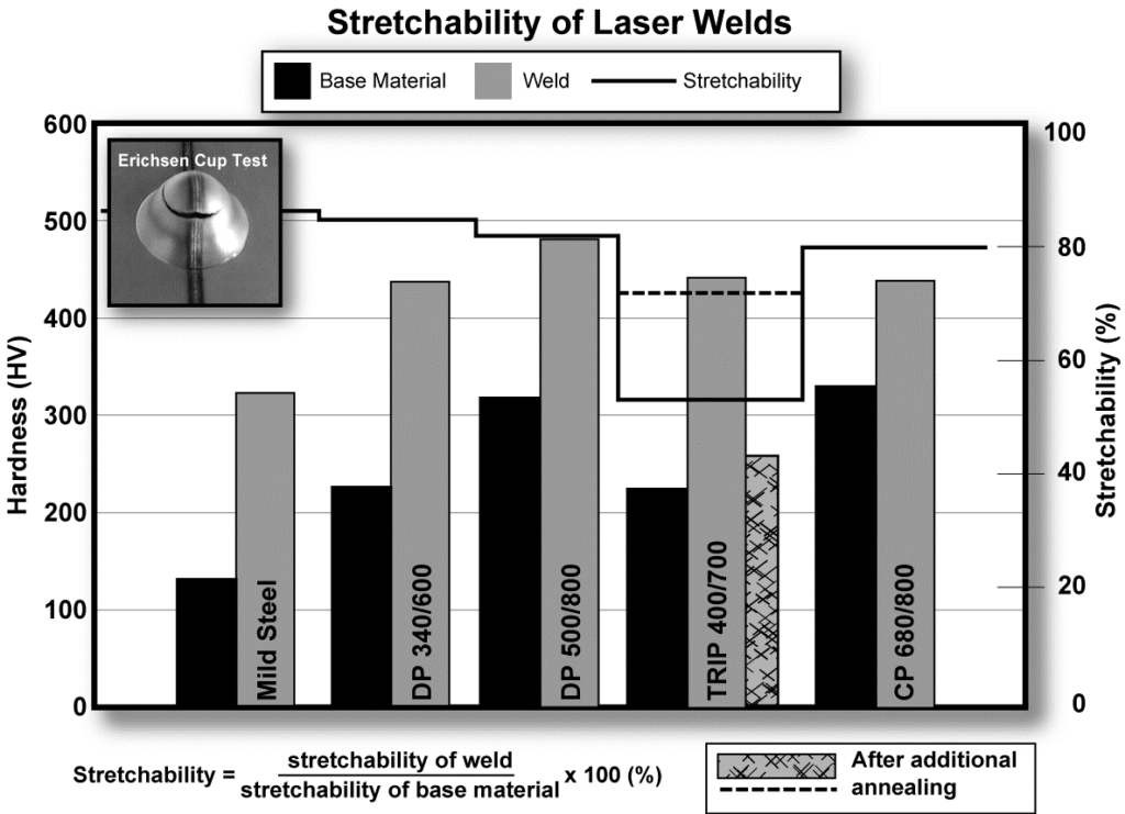
Figure 4: Hardness and stretchability of laser butt welds with two AHSS sheets of the same thickness (Erichsen test values describe the stretchability.)
The hardness of the laser welds for AHSS is higher than for mild steels (Figure 5). However, good stretchability ratios in the Erichsen test can still be achieved when the difference in hardness between weld metal and base metal is only slightly higher for AHSS compared to mild steels. If the hardness of the weld is too high, a post-annealing treatment (using HF-equipment or a second laser scan) may be used to reduce the hardness and improve the stretchability of the weld.
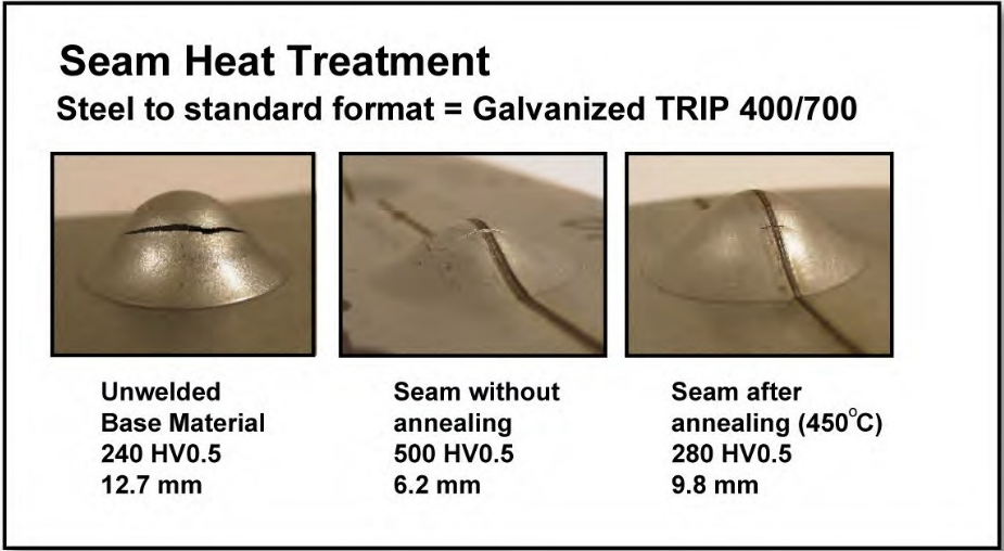
Figure 5: Improved stretchability of AHSS laser welds with an induction heating post-Heat treatment (Testing performed with Erichsen cup test)
Contributed by Menachem Kimchi, Ohio State University
Imagery and work thus represented is provided as follows:
Figure 2 and 3: Courtesy of TRUMPF
Figure 4: H. Beenken, “Joining of AHSS versus Mild Steel,” Processing State-of-the-Art Multi-phase Steel; European Automotive Supplier Conference, Berlin (September 23, 2004).
Figure 5: Courtesy of ThyssenKrupp Stahl.